Week 7 Challenge
Design and development of sliders -
A) Slider 1 -
We will create a plane by selecting the edge as slider direction as first reference and the point as second reference.
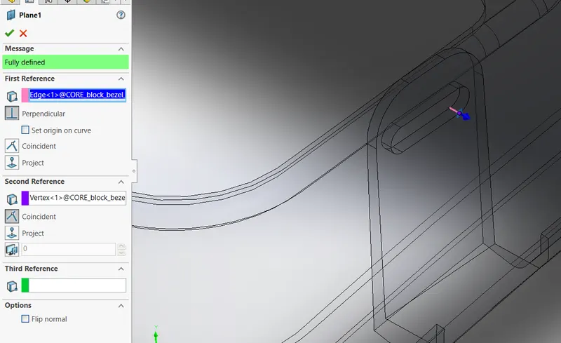
We will create a sketch on the plane , we will use convert entities and convert the profile on sketch .
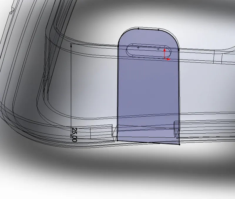
We will use the split body tool and select the sketch and plane as trim tools and and select cut bodies , then we will select the split body that we need as the slider body .
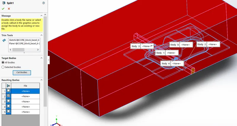
We will create another sketch on the same plane , we will convert the profile of the undercut on the sketch .
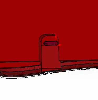
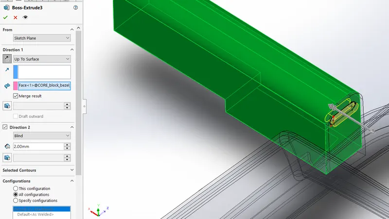
We will use the boss extrude tool and extrude the sketch upto the face of the body and other side as 2mm .
As we see there is a gap between the slider part and the profile , so we will need to fill this gap .
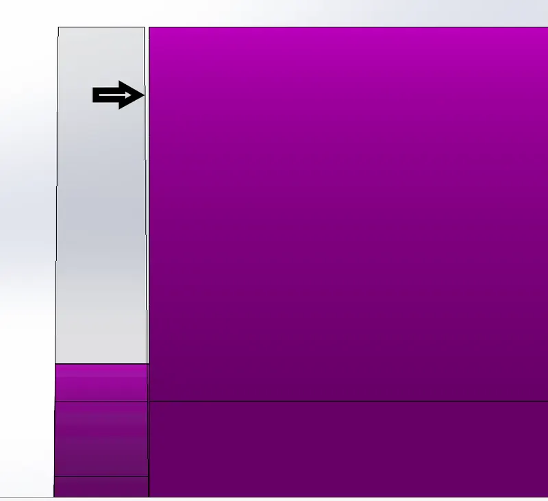
Now we will create a sketch with the profile of the slider part and then we will extrude it upto the surface such that the gap between them is filled .
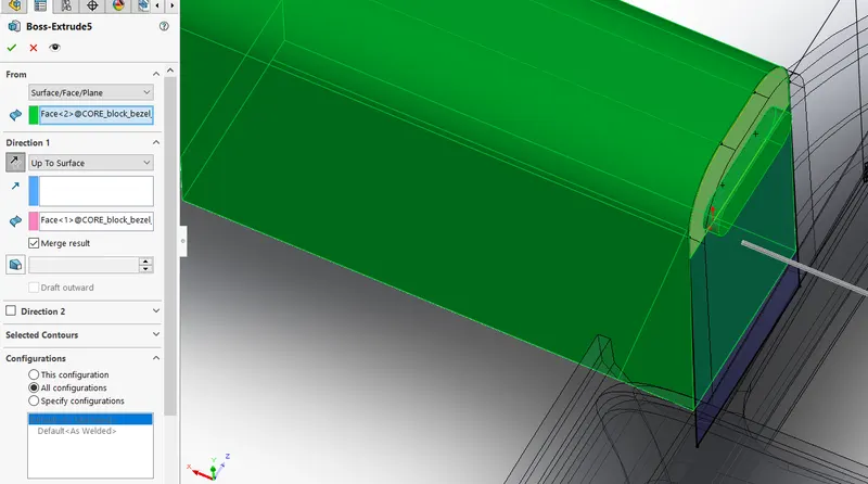
As we see below the previous gap is now filled .
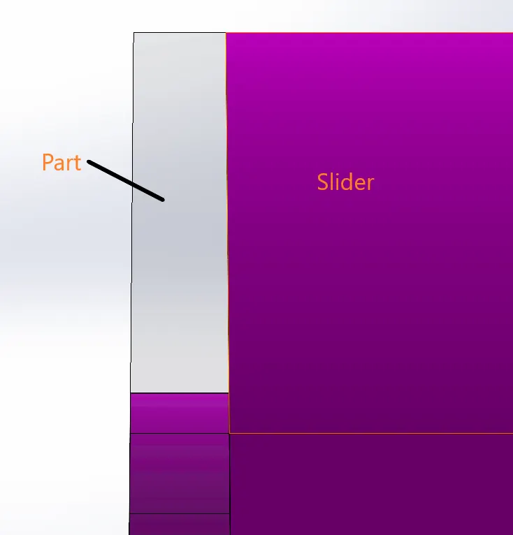
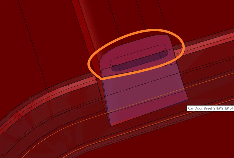
Now we will have to remove the marked profile from the core body , this is because this marked profile is in the slider body so we will not need this in core body .
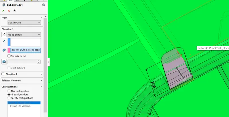
Now for this we will use the same sketch and use the cut extrude tool and cut the core body .
Now we will create a sketch of rectangle and use the slider body as shown below .
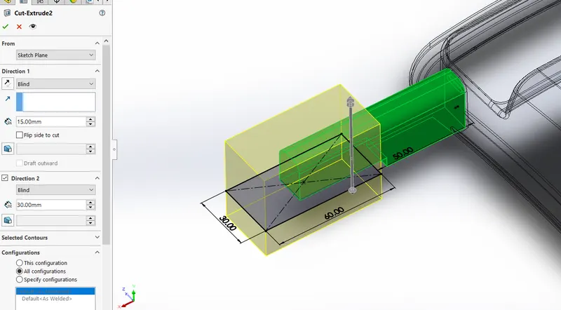
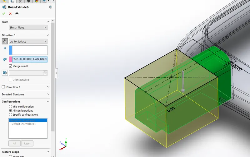
Then we will create a sketch on top face of the slider and use the boss extrude to extrude the sketch upto the bottom face of slider , we will tick the merge result and merge this extrude with slider body .
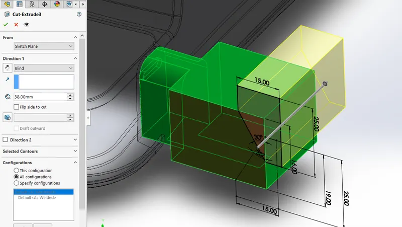
We will create a sketch on face of slider body as shown below , we will then cut extrude the slider body .
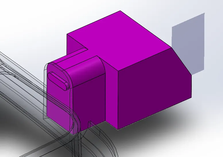
Below is the slider 1 -
B) Slider 2 -
Similar to slider 1 we will create a plane for slider 2 also .
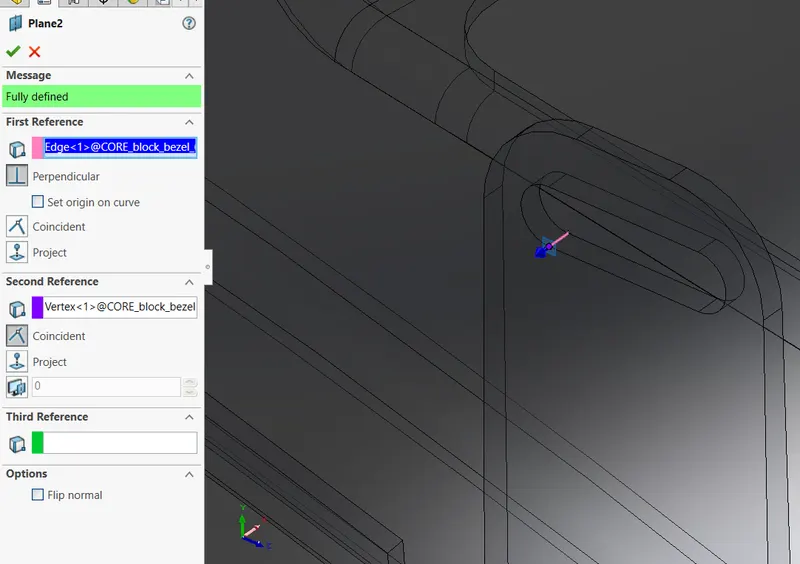
Then we will create a sketch onto that plane and convert the profile on the sketch .
Then we will use the split body tool and split the block such that we will get the slider body as shown below .
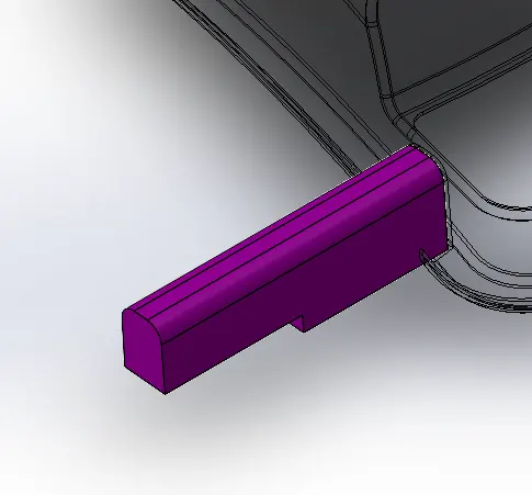
Now we will create sketch on the same plane , the sketch will be profile of the undercut slot .
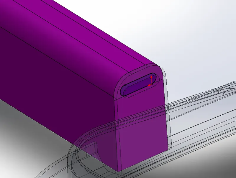
Then we will use the boss extrude tool and extrude it upto the surface and 2mm in other direction .
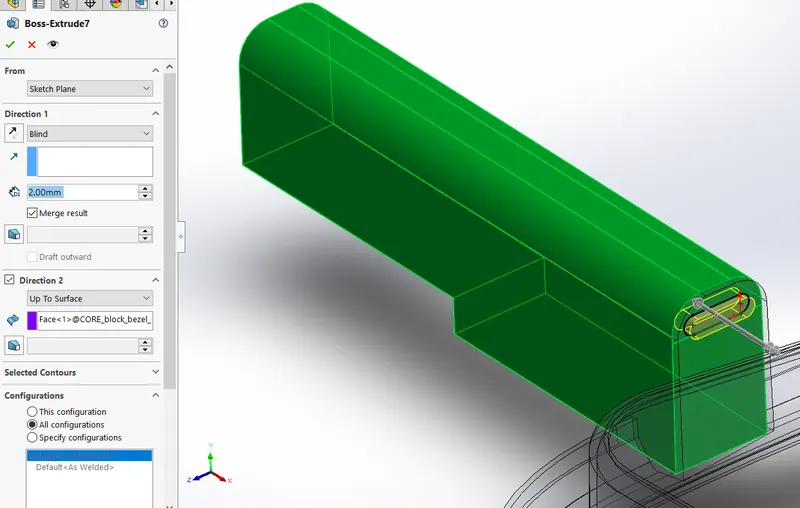
We have a gap in the slider body and the profie so we will have to fill this gap .
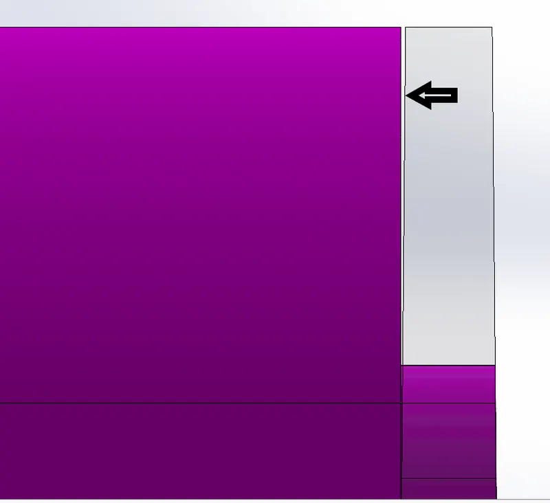
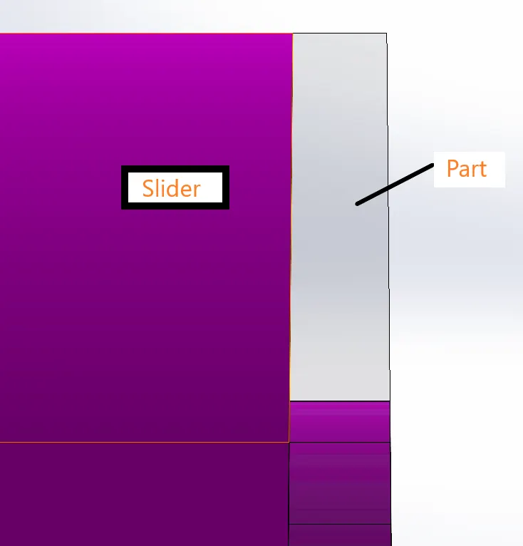
As we did for slider 1 , in same way we will create a sketch on plane with profile and then we will extrude it such that the gap is filled .
As we cwn see below the gap is now closed .
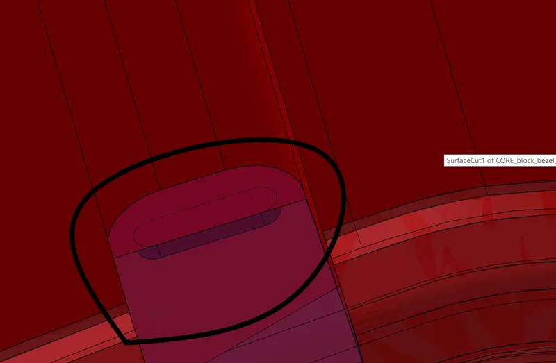
Now we will have to remove this marked additional part from the core body .
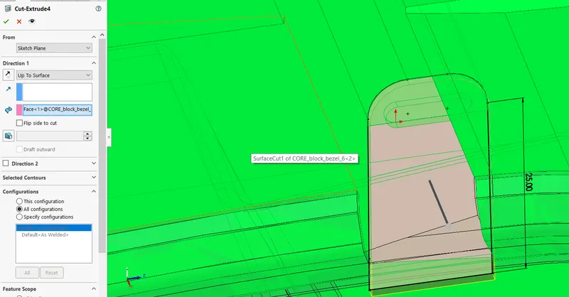
So we will create a sketch on the palne , the sketch will be of slider profile and then we will use cut extrude tool and cut the core body such that the additional parts are removed .
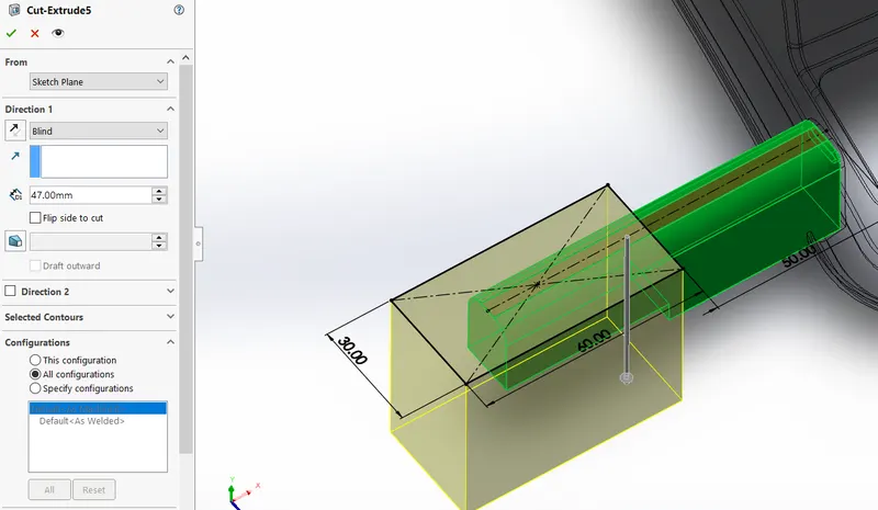
Then we will create a sketch on top face of slider body and cut extrude the slider body with the sketch as input .
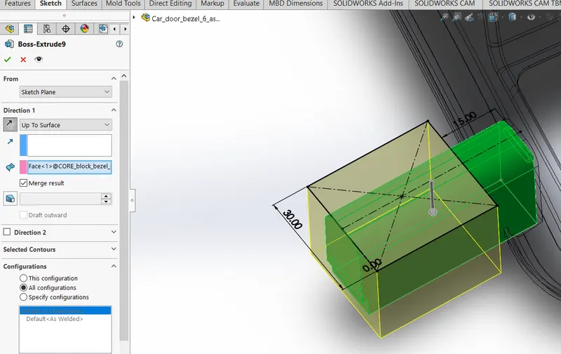
Then we will create another sketch on top face of slider body and we will boss extrude this sketch and merge it with slider body .
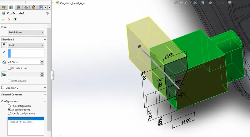
We willl create another sketch for the angle cut on the slider , we will cut the slider body with this sketch .
Below is the slider body 2 -
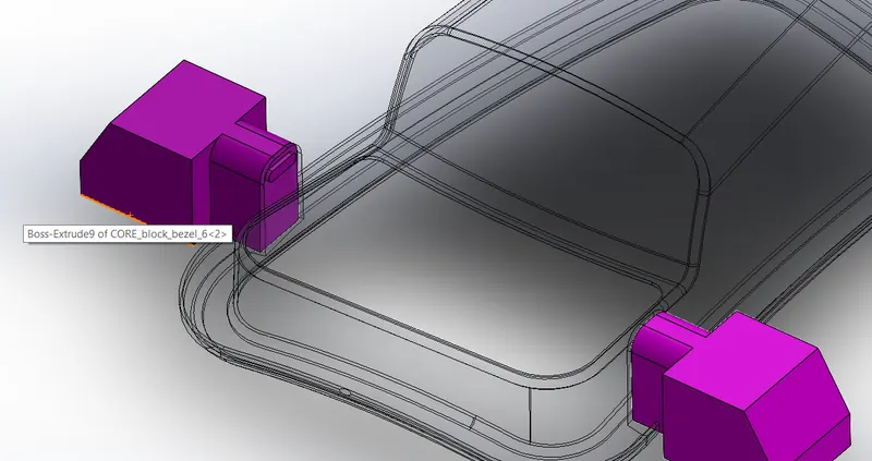
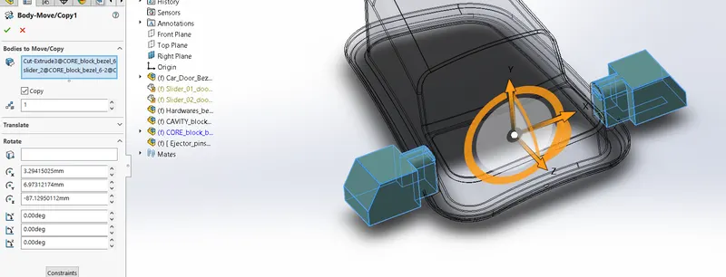
We will use the move/copy body and create a copy of the slider bodies .
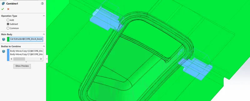
We will use the combine tool and then select subtract , select the core body as the main body and then select the two sliders as bodies to combine .
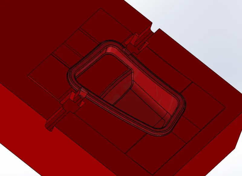
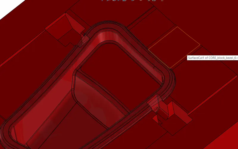
Below is the core body that we get after combine operation , now as we can see there are some additional cuts that we dont need and we will fill these cuts .
So we will use the move face tool and select the faces to offset and keep offset value as 10mm .
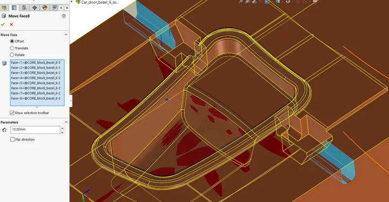
Below we can see the faces have been filled .
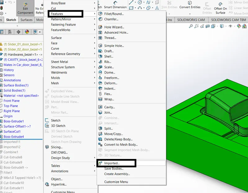
Now , next thing we will do is save the two sliders as two separate paasolid files , then we will intsert this parasolid file into cavity part . we will go to insert -features-imported , then we will select the two parasolid files to add .
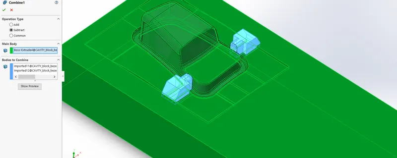
Then we will use the combine tool and select the subtract option and select the cavity body as main body and the two imported bodies as body to combine .
Now we will have to create path on the cavity block such that the two sliders can move in and out . so we will create sketch on the face as shown below and then cut extrude the cavity block .
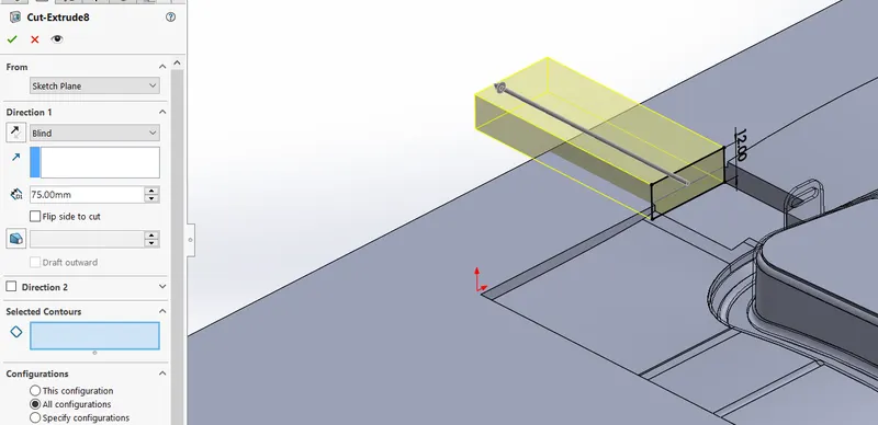
By similar way we will create path on other side . below is the two pathways on cavity block .
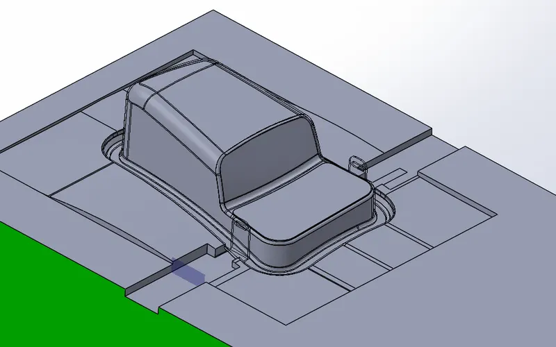
Now we will create two separate parts in the assembly workbench for slider 1 and 2 . then we will add the imported parts in that slider part files and we will modify tthem .
Then we will create sketch on the flat face of slider part , the sketch is as shown below .
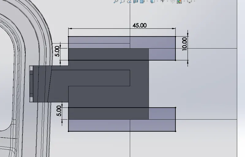
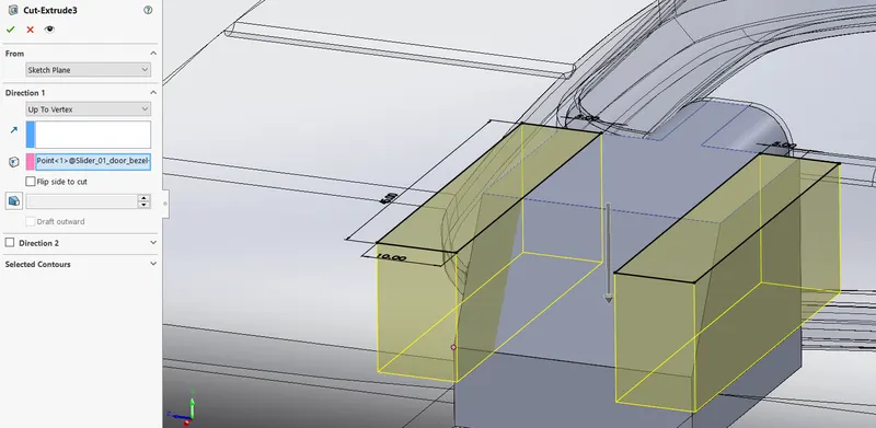
We will create cut extrude using the sketch and cut the respective slider upto the vertex .
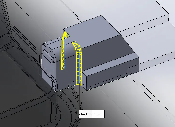
We will give fillets to the slider as shown below .
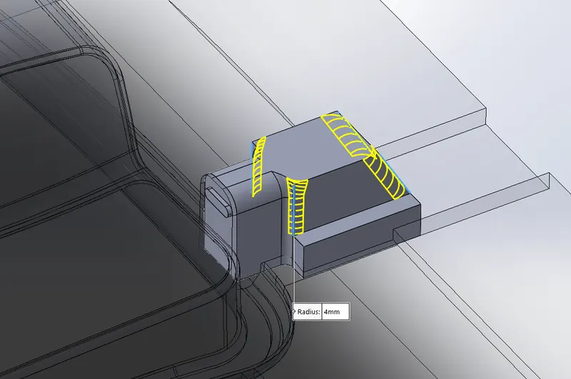
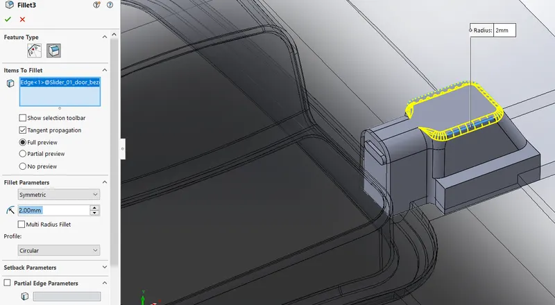
Similar to the operations done on slider 1 , we will perform same operations on slider 2 .
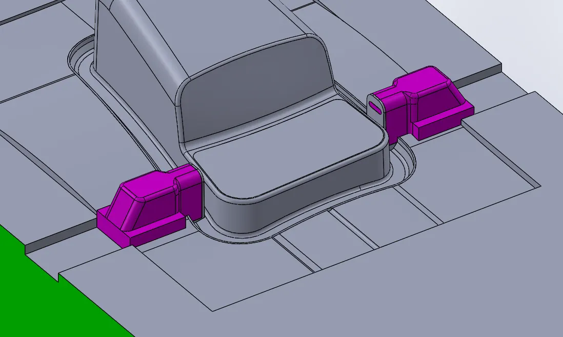
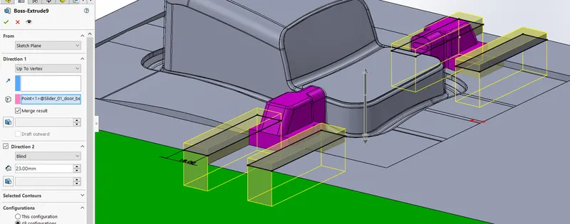
We will now proceed to create guide ways for the sliders , the sketch is as shown below .
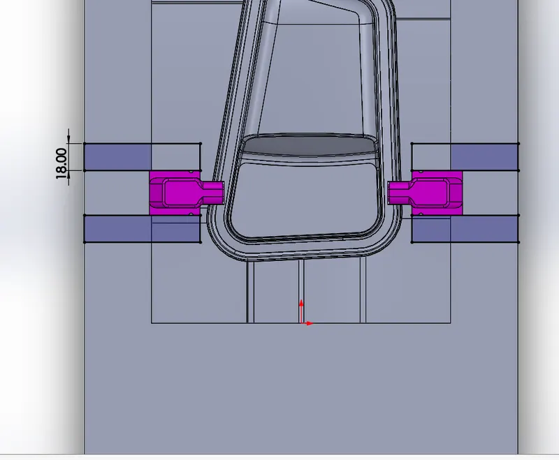
We will now extrude this sketch upto the vertex of the slider part .
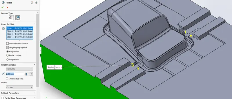
We will give fillets to the cavity body .
Hardwares -
Now we will go to create sketch for the hardware , the sketch is shown below .
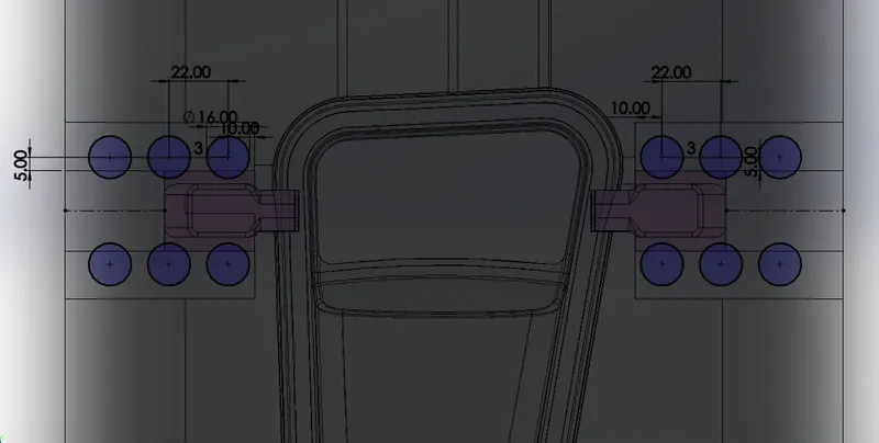
Then we will extrude this sketch for 3 mm this will be the washer body .
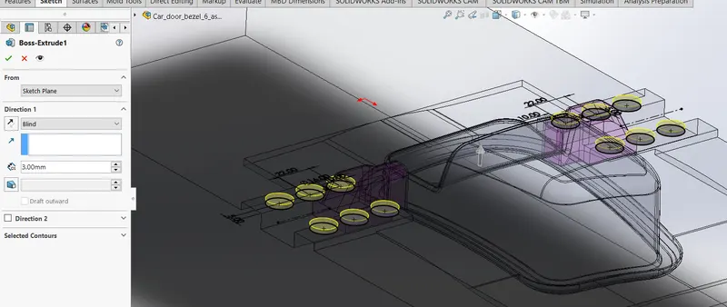
We will create another sketch on top face of washer .
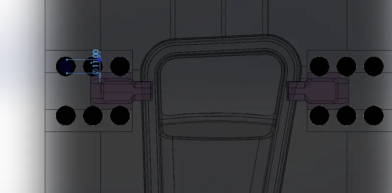
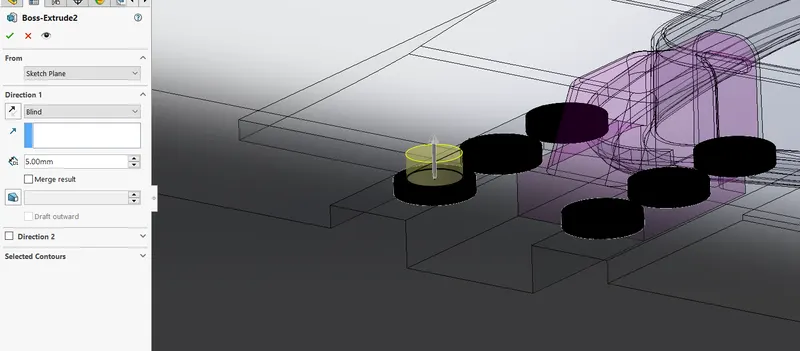
We will extrude this for 5mm and we will untick the merge result option . this will be head of the bolt .
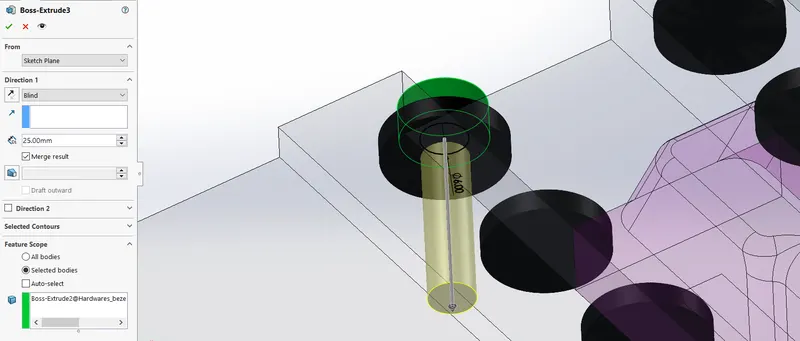
We will create another sketch on bottom face of the bolt head. the sketch will be of diameter 6 circle and we will extrude it for 25mm and merge it with bolt head .
Now we will create sketch , on top face of washer , then we will put points in the centre of the washers .
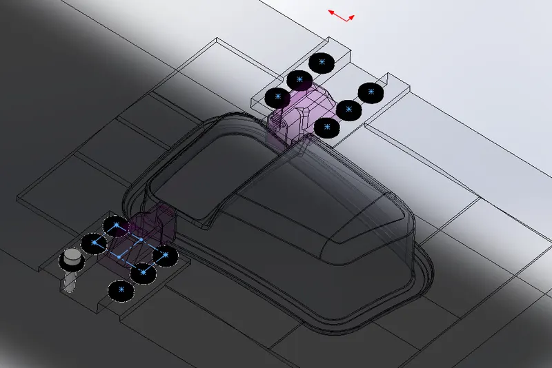
We will use the sketch pattern tool and select the sketch as input and then select the bolt body to pattern .
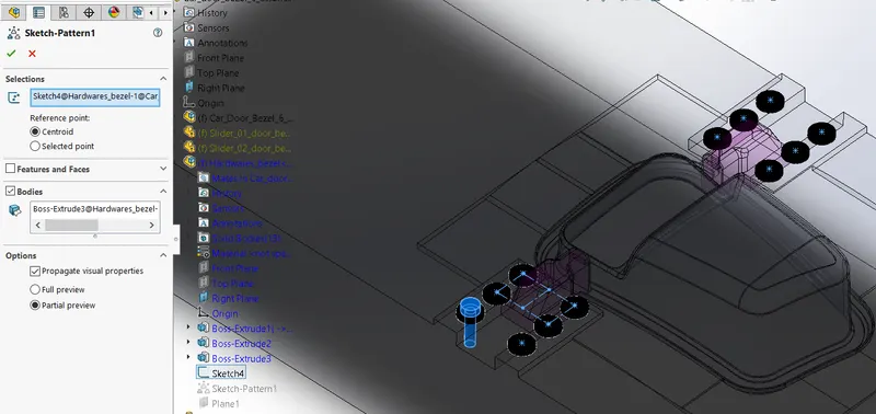
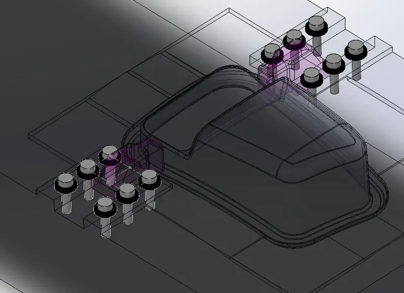
Below is the hardwares -
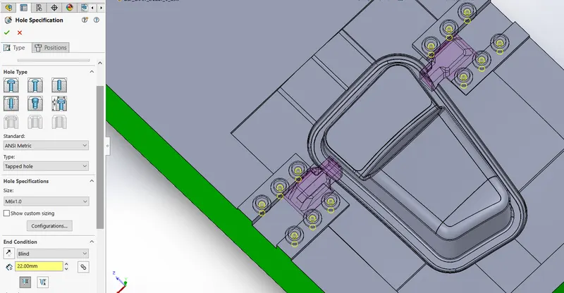
We will use the hole tool and create M6 holes on the cavity block for the respective bolts .
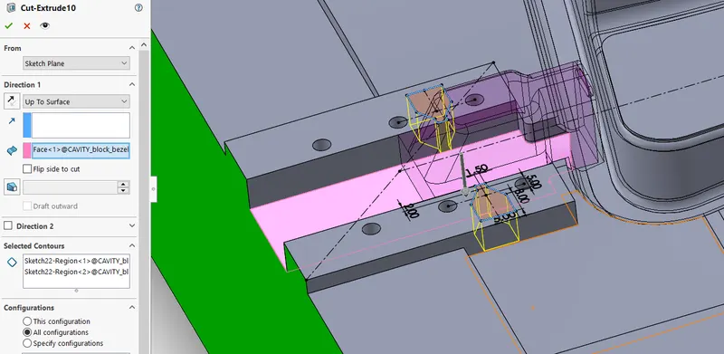
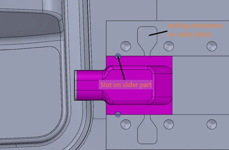
Now we will create sketch on the face on top face of guide rails , this sketch is for the locking mechanism that will be installed . the sketch is shown below .
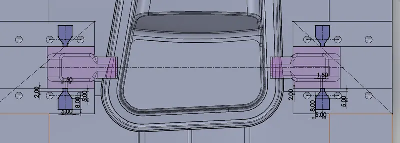
We will cut extrude the block with this sketch as input . we will select the distance as upto surface and select the face as shown below .
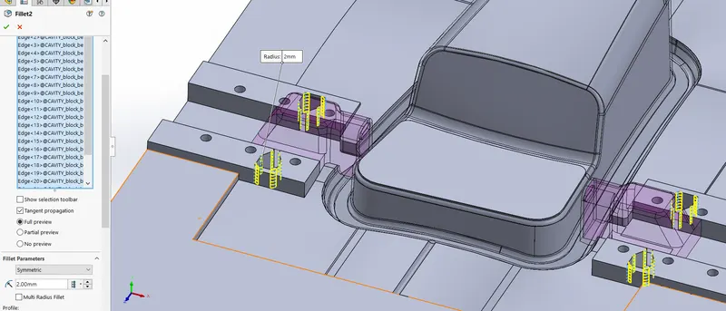
We will give fillet of 2mm for the edges of the slot .
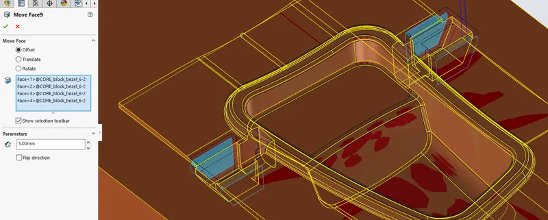
We will use the move face tool and move the faces to offset of 5mm .
we will create a sketch on flat face , the sketch is as shown below .
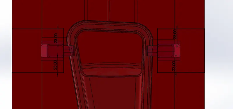
We will use the cut extrude tool and cut the block and select distance as upto vertex .
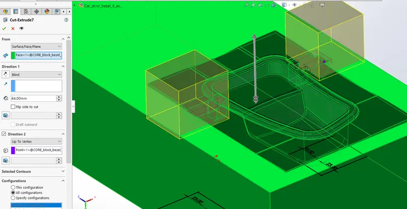
We will then give fillets to the edges where the slider will be placed .
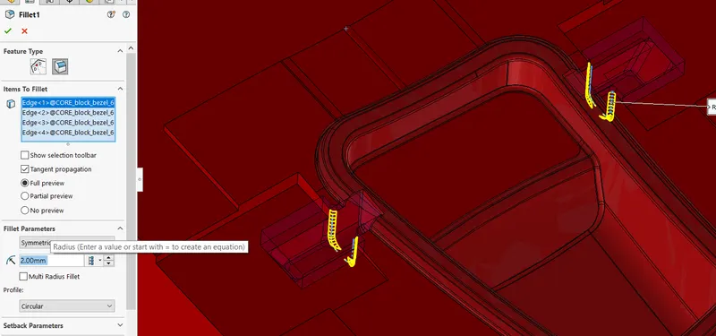
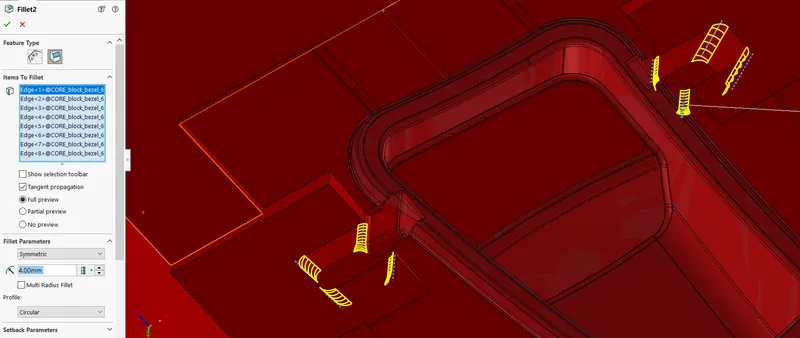
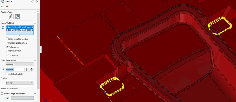
Now we will have to make clearance on the core block for the hardwares so we will create a sketch on flat face . the clearance sketch will be a circle of diameter 17mm .
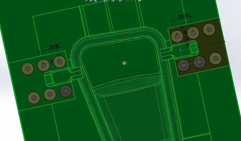
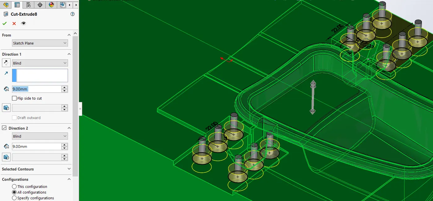
Then we will cut extrude the block with this sketch as input for 9mm deep .
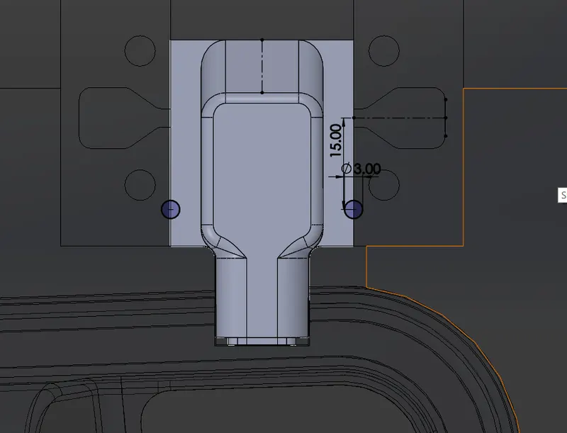
Now we will create a cut on the slider for the locking mechanism . we will create a sketch as shown below .
We will use the cut extrude tool and cut the slider part .
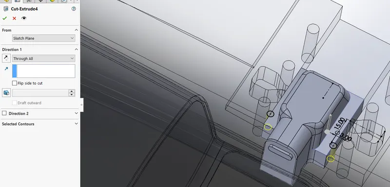
Below is shown how the holes will look on core and slider .
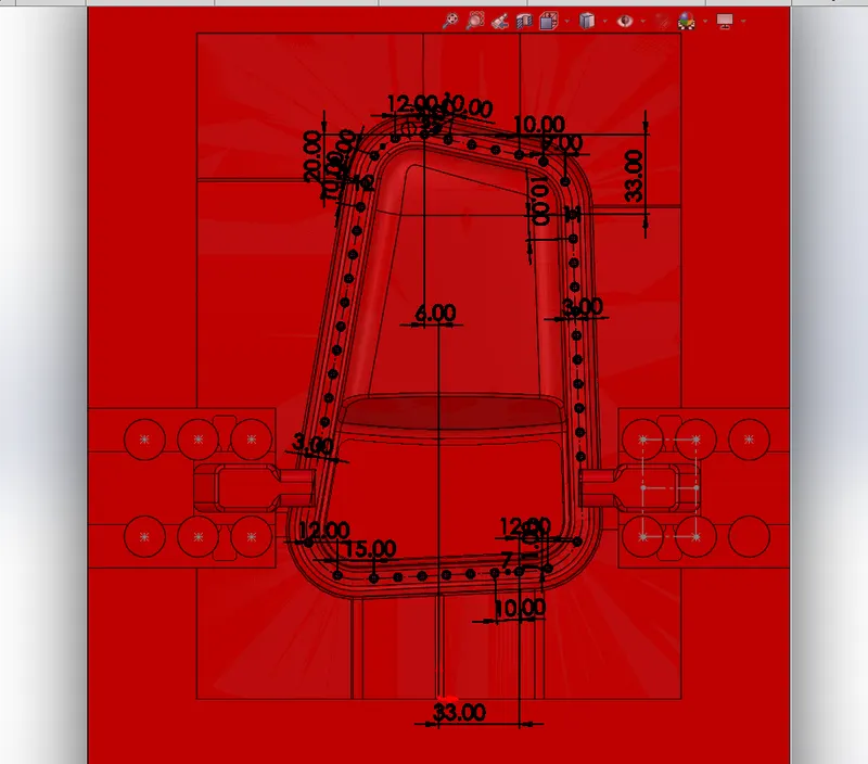
Now we will create a ejection system for the part , the ejection system will be on core side . we will create a sketch on flat bottom face of core block , then we will create a circle of diameter 3mm .
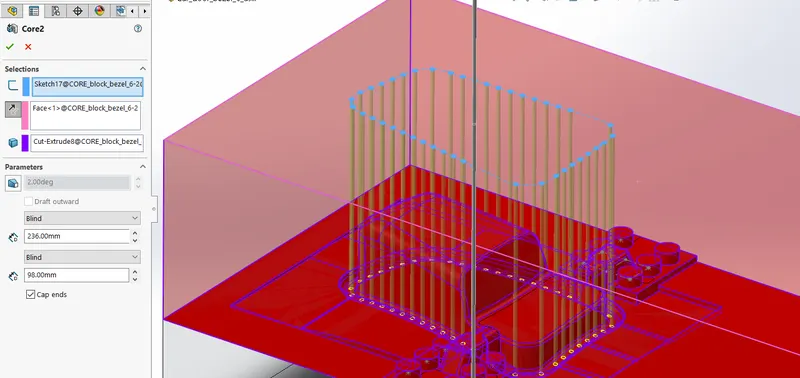
Then we will use the core tool and select the sketch as input , so we will then get yhe core pin bodies and their respective cut will be formed on core block .
Now we will have to create a clearance for the pins on the block , so we will start a sketch on bottom flat face , the sketch will be of circle of diameter 3.95mm which is the clearance size given for 3mm pins .
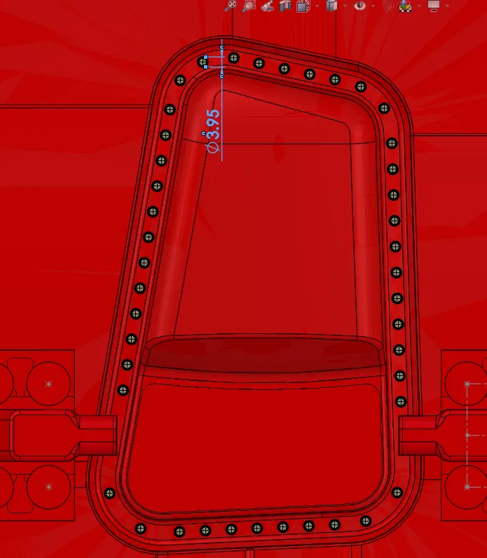
Now we will use the cut extrude tool and cut the block upto 135mm such that atleast a 10mm distance is left from top surface .
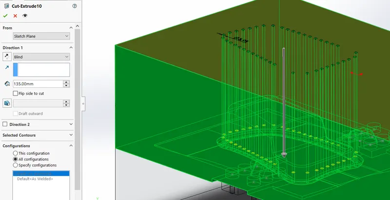
Below is the representation of core block with the clearances . we will save the corepins as a separate file .
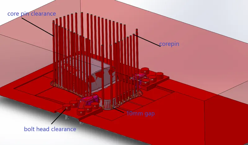
Final assembly of the blocks -
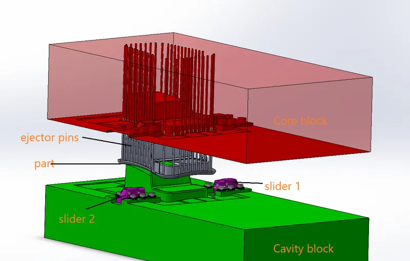
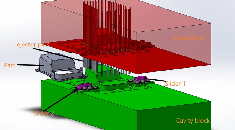
First the core block along with the part will move outwards, the slider will also move outwards with respect to their slider tooling direction .
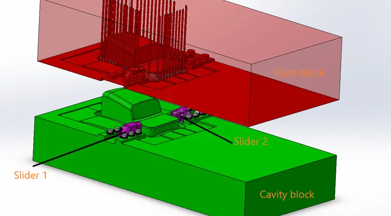
The ejector pins will move the part outward .