Week 8:- 3D Finishing - Challenges 1
1 - WHAT DO YOU UNDERSTAND BY 3D FINISH PROCESS?
ANS -
- 3D finish is a process where design is being completely finished and is made ready for final simulation .
- While doing the 3d finish process every component in the assembly is designed properly and does not have interference with other parts .
- Every holes must be checked for their concentricity and their sizes . the nominality of holes should also be checked so that no problem will arise while assembling of parts .
- Fastners should be added in design to check if it fits the design .
- Proper renaming of parts / assemblies should be done .
2 - WHAT ARE THE POINTS NEED TO BE TAKEN CARE OF WHILE FINISHING THE DESIGN?
ANS -
a) Hole concentricity and hole sizes - All the holes in the assembly should be checked for their concentricity . all the hole sizes should be checked like the thread length , hole dia , counterbore hole size etc .
b) Machining area - There are some parts which require some machining operation , because while assembling a good machined surface will result in better assembly . so we need to highlight the machined area in our design by using a standard colour code . Machining only on required faces will reduce cost of manufacturing and also increases accuracy of dimension .
c) Nominality - All units should be checked for nominality for ease of assembly .
d) Holes coloring standard - For ease of identification of the purpose of hole , holes should be given color in design as per the standard . some example is blue color given to dowel hole , yellow color for the threaded hole , cyan color for open hole.
e) Pneumatic layout - Pneumatic layouting is a process of properly positioning the pneumatic pipe used in the assembly such that it does not interfere with other parts . so layouting should be done .
f) Gap checking - Gaps should be checked within different units and between other units to avoid interference between parts.
g) Fasteners implementation - All the fasteners should be added in the assembly to check which fastners , their height , length, thread pitch , etc would be needed in the final assembly .
h) Avoiding clash between different parts - All the parts in the design should be checked thoroughly so that it does not cause interference with other parts.
i) Mylars splitting as per panel profile - Mylar splitting should be done as per panel profile while finishing design . the thickness of panel should be considered while splitting .
j) Proper renaming of parts and assemblies as per standard - For ease in identification of parts , proper renaming of parts and assembly should be done as per standard .
3- WHAT ARE ROUGH LOCATORS AND WHAT IS THEIR USE?
ANS -
- Locating is an important factor that we need to consider because for the welding operation the workpiece should be placed in proper position so that the welding is done in correct welding spots in workpiece .
- For this rough locators are used , rough locators are used to locate the panels while loading and unloading .
- Rough locators are used to guide the panel in correct position and orientation .
- A rough locator can be a standard part or a make part .
- It also helps in proper poka - yoke . it also results in fool-proofing because due to use of rough locator the panel cannot be placed in wrong position .
4 - WHAT ARE THE POINTS YOU NEED TO CONSIDER WHILE DESIGNING ROUGH LOCATOR?
ANS -
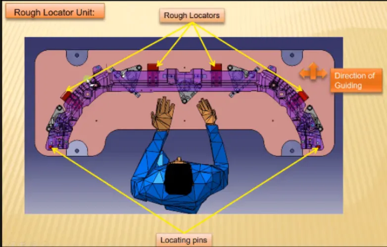
- The height of rough locators should not be more than permissible ergo height of fixture .
- The entry point / top point of rough locator must be 10 -15 mm above panel surface .
- Rough locators should have adjustment in direction of guiding plane, for this slots can be provided .
- A gap of 2mm should be maintained between rough locator and the panel at time of design .
- We can provide adjustment of 5 - 10mm in +ve and -ve direction of guide plane .
- Rough locators can be rod type or flat type depending upon the standard and other condition .
5 - WHAT IS THE GUN STUDY PROCESS?
ANS -
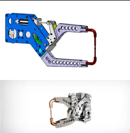
- Welding is a process widely used in automobile industry for joining of components together . so the requirement of welding fixture for ease of welding is a continous development task in industry.
- For the welding of panel we identify points / position where the welding spots will be done. during the design stage we place gun on these weld points to ensure that the gun does not interfere with the other parts . this is known as gun study .
- Gun study process is an important factor as after we do this study we come to know if the Weld gun interferes with other parts and we can then make the changes in design according to this .
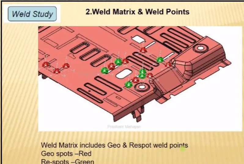
- The weld gun study includes information of weld gun detail , weld matrix and weld points . there are two types of weld points geo-spot weld points and re-spot weld points.
- In weld study , the gun which will be used for welding is used in 3d software to mount on the weld points and check the weld gun feasibility .
6 - WHAT ARE THE POINTS NEED TO CONSIDER DURING GUN STUDY?
ANS -
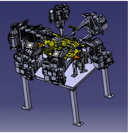
- The axis of the weld spot along welding direction must be normal to the weld surface .
- The no . of weld spots for the panel , the time required to spot each weld , determines the total time required to complete all the weld spots .
- If we have one or more devices and we want to program , the behaviour of each model in work cell can be simulated over time .
- Instructions for each device are coded by giving sequences . the sequences define motion , manipulation and action of devices .
- Based on the distance of each tag point from home position , motion type , speed and acceleration , one can obtain cycle time for each device assigned with sequences . by this way the robot cycle time is calculated.
- After sequencing all the device , a simulation is done with collision check on and made sure that welding operation is collision free .
7 - WHAT IS PNEUMATIC ROUTING?
ANS -
- Pneumatic system is a air operated system which uses pressurised air to do the opening and closing action of the cylinder .
- Pneumatic system is mostly preferred for the BIW parts .
- All toggle clamp , pin cylinder , slides etc are operated via pneumatic , generally cylinder are designed to operate at max 12 - 15 bar .
- As it is expensive to maintain 10-12 bar in the shop floor it is preferred to design pneumatic system at 6 bar pressure.
- Proper pneumatic layout or routing is very important to be shown in the design as it helps in describing best possible way to keep all pneumatic pipes clean and away from any welding spatter which may cause wear and tear of pneumatic pipe.
- In pneumatic layouting all pipes from cylinders are shown connected to valve banks and passes through a safety box like a structure .
- Major suppliers for pneumatic are SMC , Teunkers , Festo , CKD etc.
8 - WHAT IS SOLENOID VALVE ?
ANS -
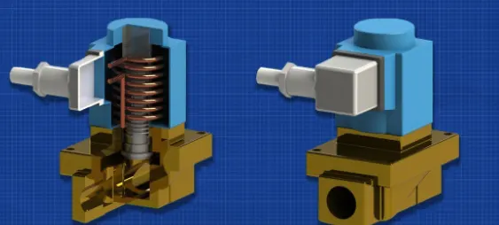
- Solenoid valve is an electrically controlled valve which is used to actuate the airflow in cylinder as per the sequence .
- The solenoid valve has a solenoid , which is an electric coil with a movable ferromagnetic core (plunger) in its centre .
- The working is like ,in rest position the plunger closes off the small orifice . an electric current through the coil creates the magnetic field . the magnetic field exerts an upward force on plunger opening the orifice .
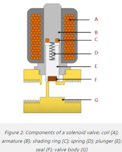
- The solenoid has two components that is a solenoid and valve body (G) .a solenoid has a electromagnetically conductive coil (A) around an iron core at centre called the plunger (E) . at rest it can be normally open or normally close .in de-energized state , a normally open valve is open and normally close valve is close .
- when current flows through the solenoid the coil is energized and creates a magnetic field . this creates a magnetic attraction moving it and overcoming the spring force .
- If the valve is normally closed the plunger is lifted so that the seal (F) opens the orifice and allows the flow of air through the valve . if the valve is normally open the plunger moves downward so that the seal (F) blocks the orifice and stops the flow of air through the valve.
- The ring (C) prevents vibration and humming in AC coils.
9 - WHAT IS VALVE BANK ?
ANS -
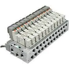
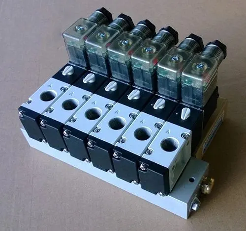
- A valve bank is a arrangement of number of solenoid valves .
- Valve bank is basically a system in which 'n' number of solenoid valves are mounted in order to maintain one common inlet and outlet of air to all valves.
- Valve banks are mostly mounted on fixture side or on the base plate depending upon various condition.
- ex - if we operate 4 operating sequence in one process of cylinder , this means we will use 4 solenoid valve corresponding to 4 different sequences and for these 4 valves to be mounted together on one valve bank , this means a valve bank with 4+1 station is used , extra bank station will be kept as a spare.
- Valve banks are kept in a position such that it can be easily accessible for maintenanace purposes .
- Valve banks must be covered with sheet structures to avoid any damage .
- Major suppliers for the valve bank are SMC , Festo , CKD , etc .
- Valve banks are designed for higher temperature environments.
- It uses aluminium alloy manifold for less weight.
10 - WHAT IS SENSOR AND BRIEF ABOUT ITS APPLICATION IN AUTOMATION ?
ANS -
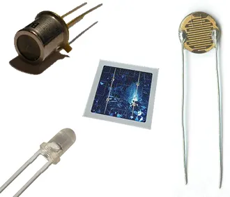
- A sensor is a device that detects and responds to some type of input from physical environment . the specific input could be heat , light , motion , moisture , or any other environment factors.
- In fixture , it is used to sense panel using electrical sensors . this is known as sensor unit . this signal sensed will be transferred to the plc for execution for further operation .
- sensor unit is used to sense whether all the components that are to be welded are present . if a particular component is missing the sensor will not be able to sense it and thus it will cause an error .
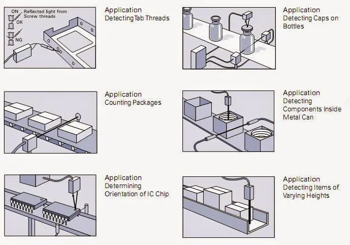
Application in automation -
- Sensors play an crucial role in industrial automation . It allows one to detect , analyze , measure and process a variety of transformations like alteraction in length , height , position , and dislocation that occurs in industrial sites .
- These sensors play an important role in predicting and preventing numerous potential proceedings thus catering to requirement of many sensible application .
- the various of sensors available are proximity , vision , ultrasonic ,temperature, inclination, position , photoelectric etc.
11 - WHAT ARE THE TYPES OF SENSOR ?
ANS -
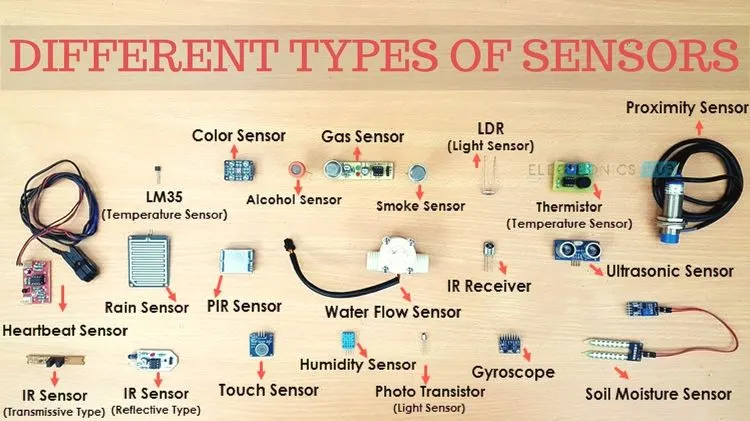
Following is the list of different types of sensors available which have various application -
- Temperature sensor - a temperature sensor is used to measure the temperature of the surrounding environment . it lets us know about the changes in temperature .
- Proximity sensor - a proximity sensor is used to sense the presence of nearby objects without any physical contact .
- Vision sensor - a vision sensor uses camera to determine presence , orientataion and accuracy of parts.
- Ultrasonic sensor - it is a device which measures distance of target object using ultrasonic frequencies and converts this sound into electrical signal.
- Photoelectric sensor - it is used to determine presence , absence , distance of an object using light transmitter and a photoelectric receiver.
- Inclination sensor - it takes non contact measurement of inclination of an object with respect to earths gravity .
- Accelerometer - It is used to measure the acceleration of an object .
- Infrared sensor(IR) - it measures infrared light radiating from objects in its field of view.
- Touch sensor - it is used to detect touch .
- Humidity sensor - it is used to detect humidity in the environment and converts this into the electrical signal.
- Color sensor - it is used to detect the different types of color.
- Flow and level sensor - It is used to meaure the level of liquids , fluids etc in an open or closed system.
12 - WHAT ARE THE FUNDAMENTAL POINTS THAT NEED TO CONSIDER WHILE DESIGNING OR SELECTION OF SENSOR ?
ANS -
- Every single loose panel which is present for the welding operation in tol should be sensed.
- Every panel should be sensed by 1 or 2 sensors depending upon the size of the panel . sensors are preferred to be in diagonal opposite ends of panel.
- the number of sensors used should be equal or more to the number of panels in the welding operation.
- Every sensor should be mounted in 3 direction adjustable way in general .
- The signal from the sensor should be sent to plc so that next opeation can take place .
- Some major manufacturers of sensors sre IFm , SICK , OMRON etc.