Advanced Sheet Metal Design Using NX Cad Challenge_2_Box Assembly
TITLE- BOX ASSEMBLY DESIGN USING NX CAD
OBJECTIVE- we will design a box with hinges and lid such that it can open or close . we will create it in sheetmetal workbench of Nx cad .
INTRODUCTION- Nx cad software is a simple and powerful tool which has wide variety of application in various industries such as automobile , medical , aircraft etc . using the sheetmetal workbench from nx , we will create the required part
DESIGN METHODOLOGY -
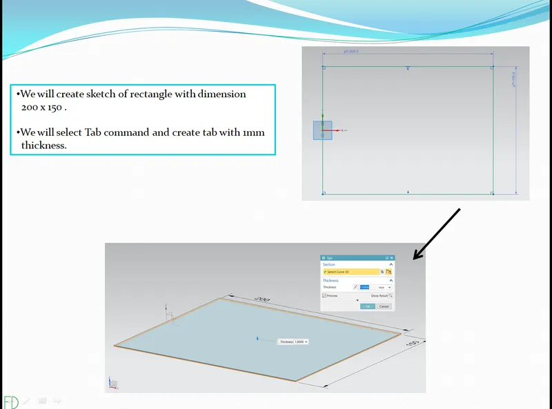
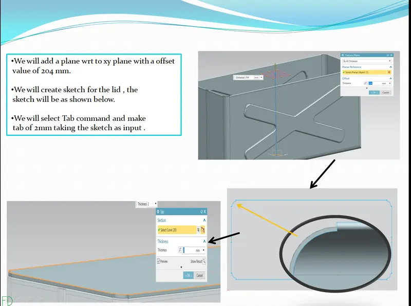
1 - Creating sketch and tab .
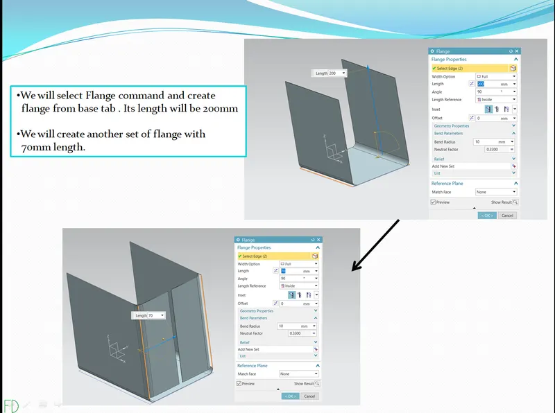
2 - creating flange .
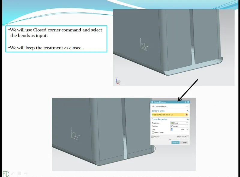
3 - Creating closed corner .
4 - Creating flanges .
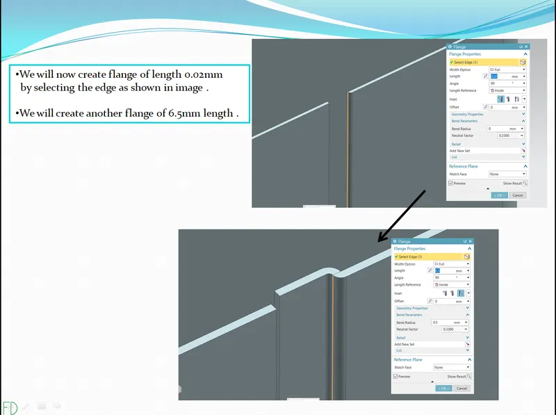
5 - Creating flanges on other side .
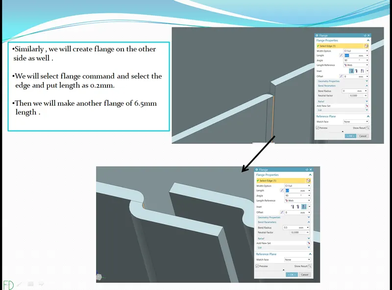
6 - Creating hem flange .
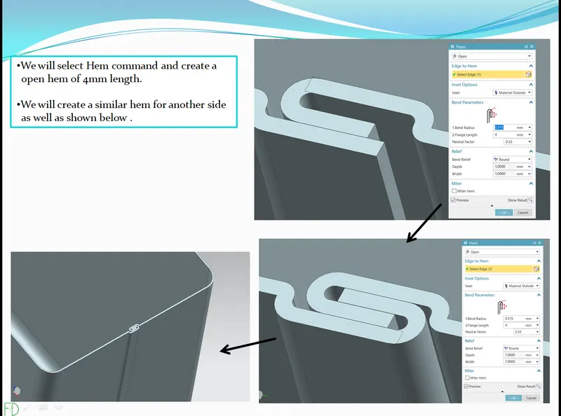
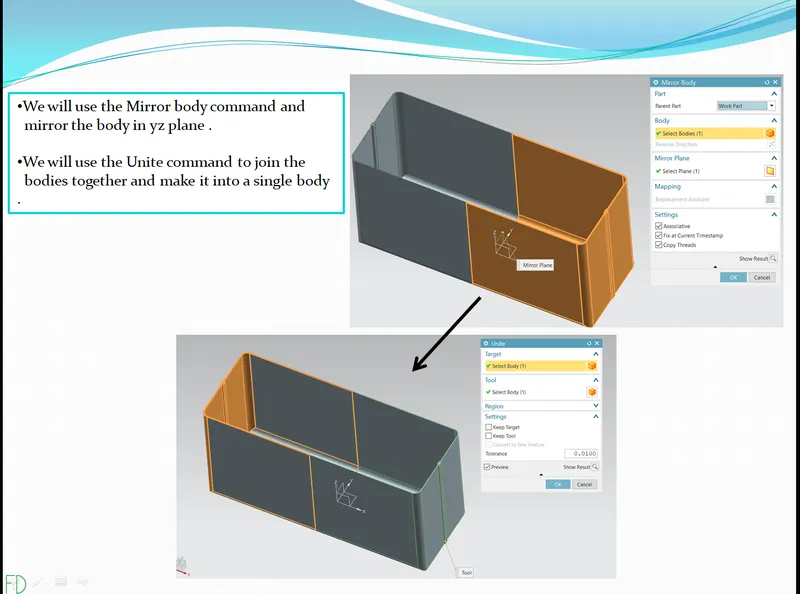
7 - creating mirror body and uniting it together .
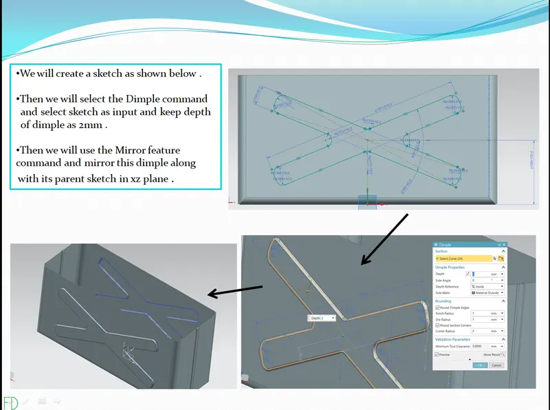
8 - Creating sketch and dimple and mirroring the dimple .
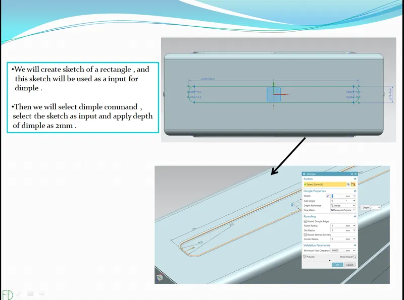
9 - Creating sketch and dimple at base .
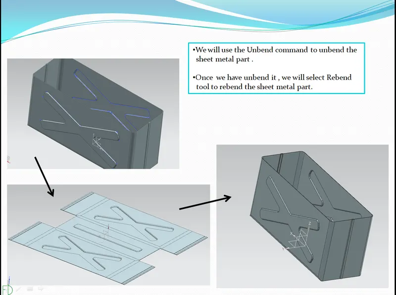
10 - Unbending and Rebending the part .
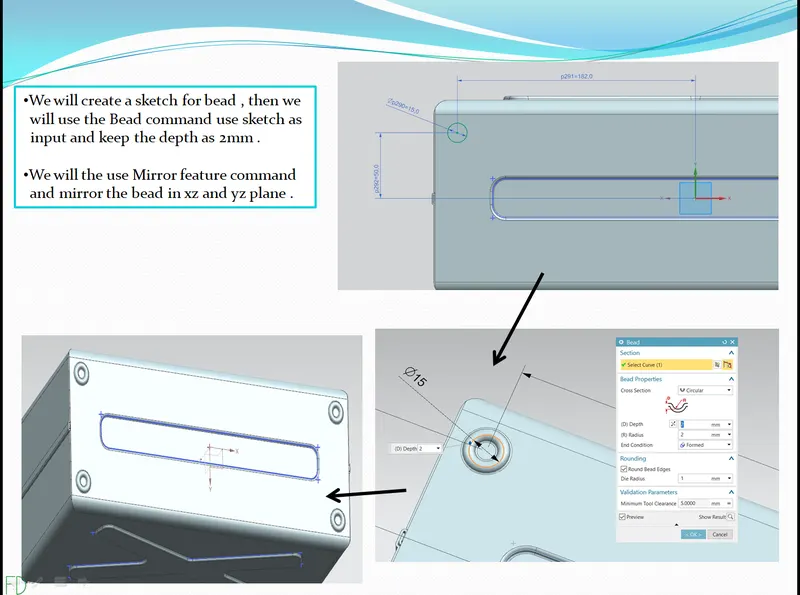
11- Creating sketch and dimple .
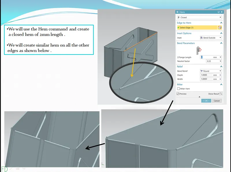
12 - Creating hem flange .
13 - Creating sketch and tab for lid .
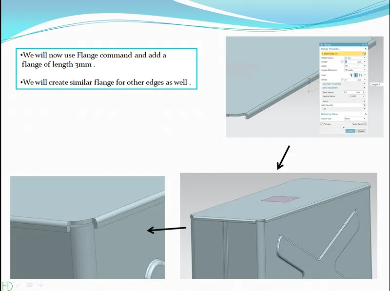
14 - Creating flange .
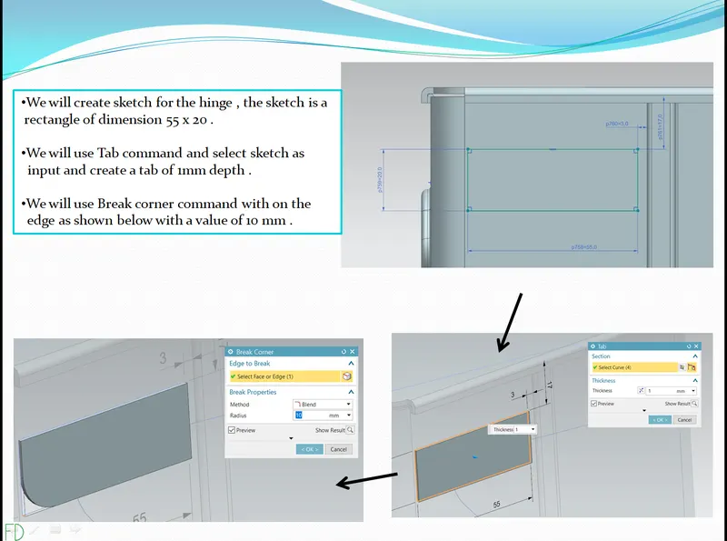
15 - creating sketch and tab for hinge1 .
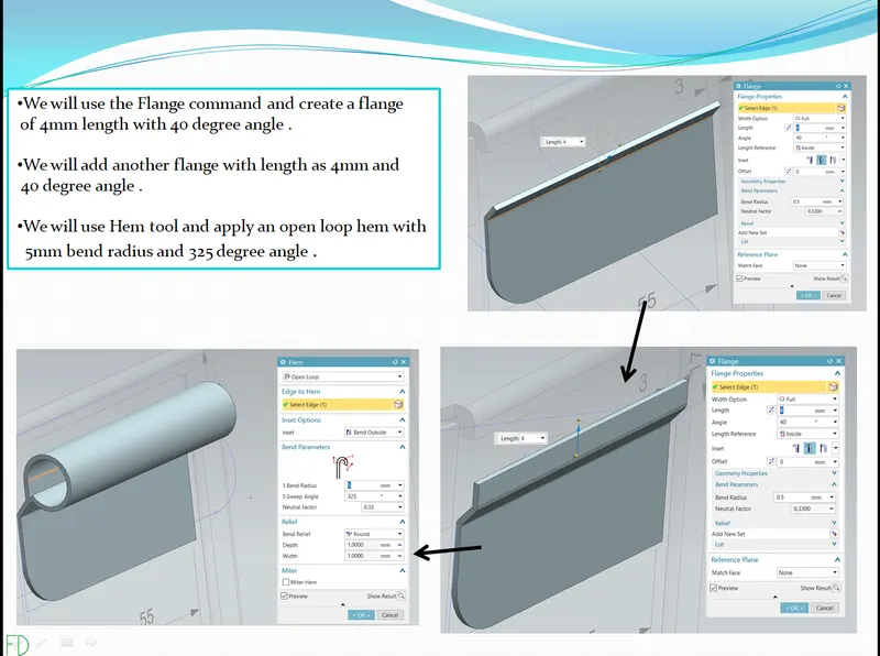
16 - Creating flange .
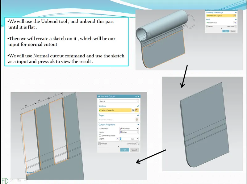
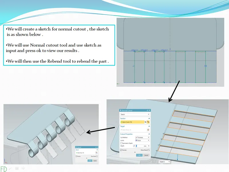
17 - Unbending and using normal cutout tool .
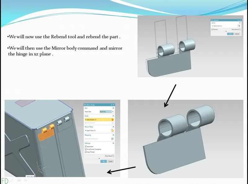
18 - Rebending and mirroring the part .
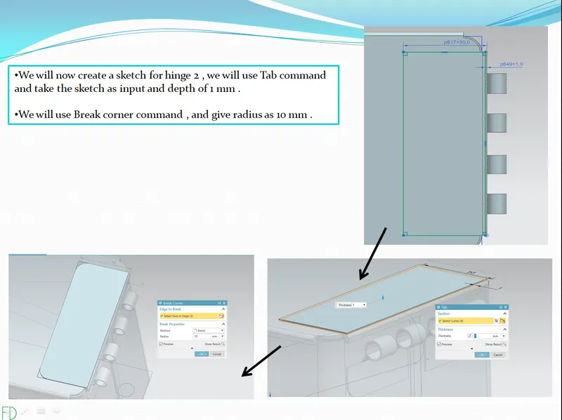
19 - Creating sketch and tab for hinge2 .
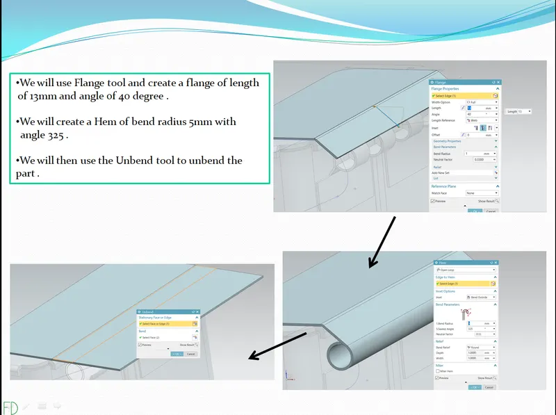
20 - creating flange .
21 - Creating normal cutout .
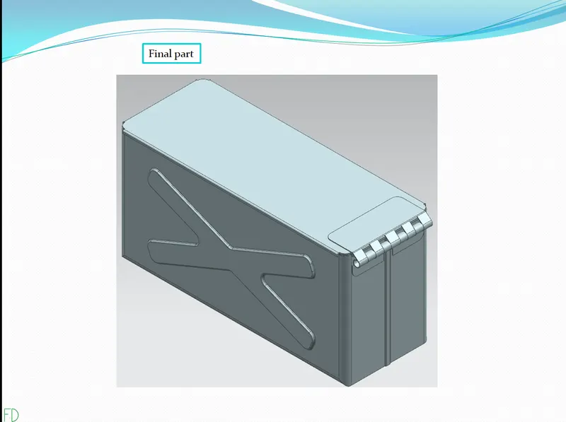
22 - Final part .
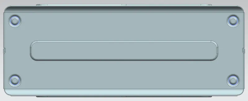
23 - TOP VIEW of base part .
24 - FRONT VIEW of base part .
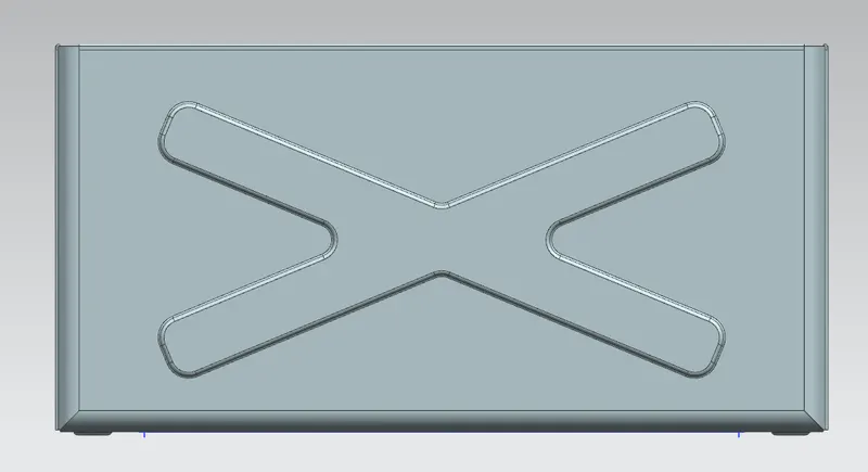
25 - SIDE VIEW of base part .
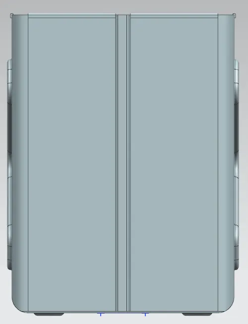
26 - ISOMETRIC VIEW of base part .
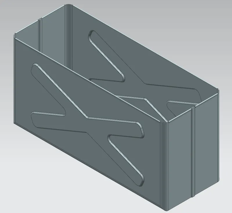
27 - TOP VIEW of lid .
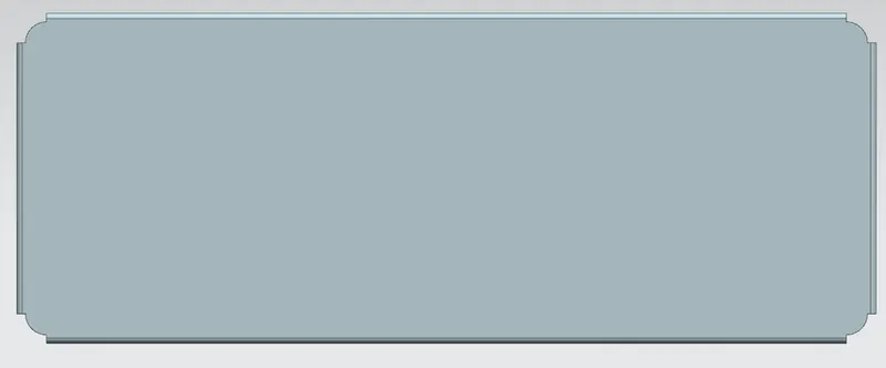
28 - FRONT VIEW of lid .

29 - SIDE VIEW of lid .

30 - ISOMETRIC VIEW of lid .
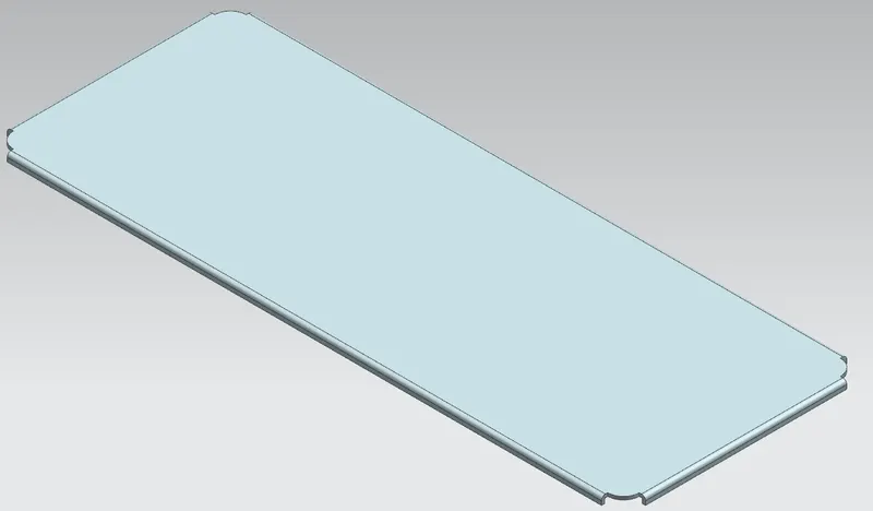
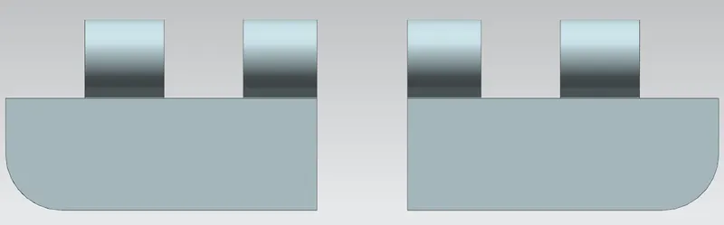
31 - TOP VIEW of hinge 1 .
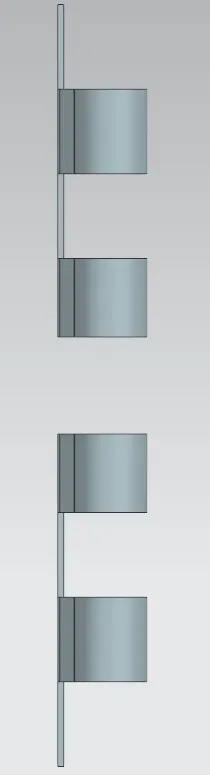
32 - FRONT VIEW of hinge 1 .
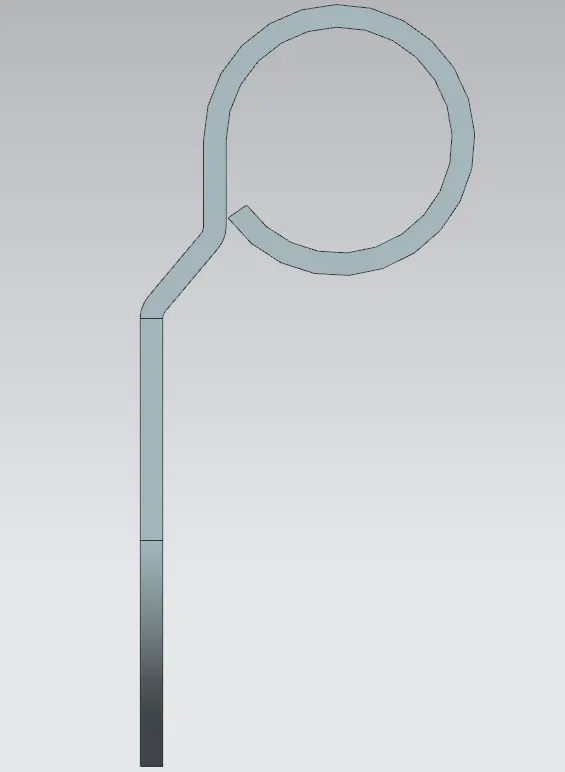
33 -SIDE VIEW of hinge 1 .
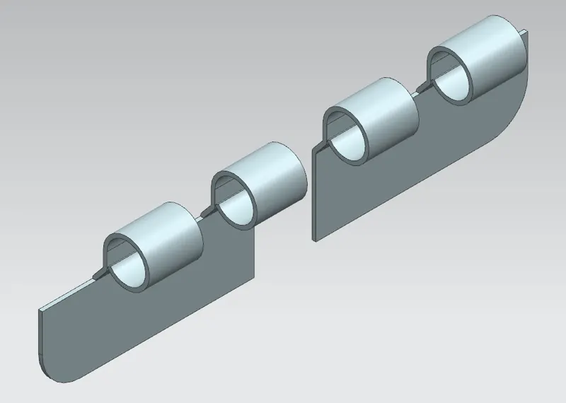
34 - ISOMETRIC VIEW of hinge 1 .
35 - TOP VIEW of hinge 2 .
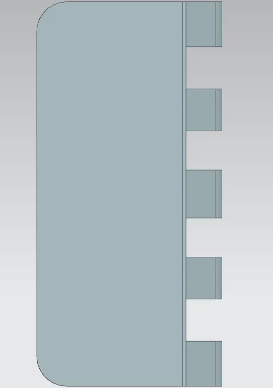
36 - FRONT VIEW of hinge 2 .
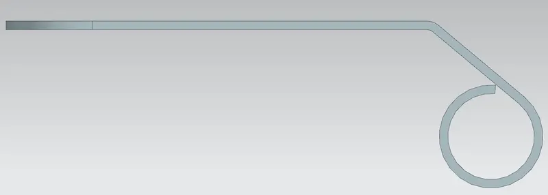
37 - SIDE VIEW of hinge 2 .

38 - ISOMETRIC VIEW of hinge 2 .
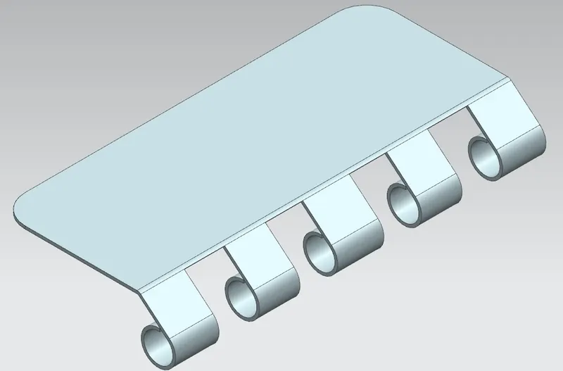
39 - TOP VIEW of box assembly .
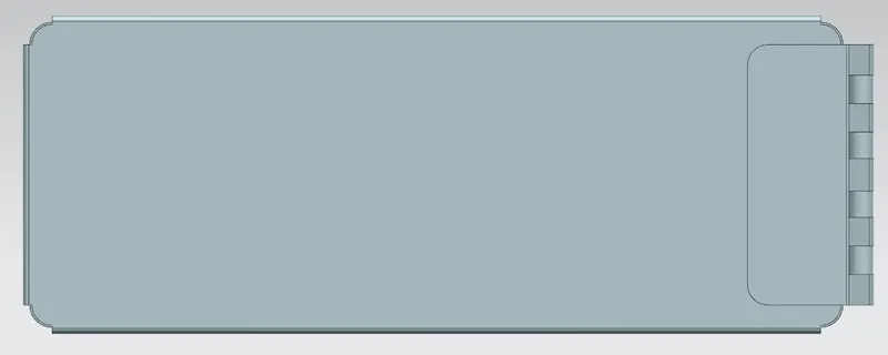
40 - FRONT VIEW of box assenbly .
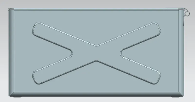
41 - SIDE VIEW of box assembly .
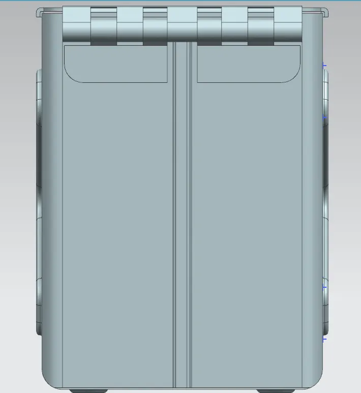
42 - ISOMETRIC VIEW of box assembly .
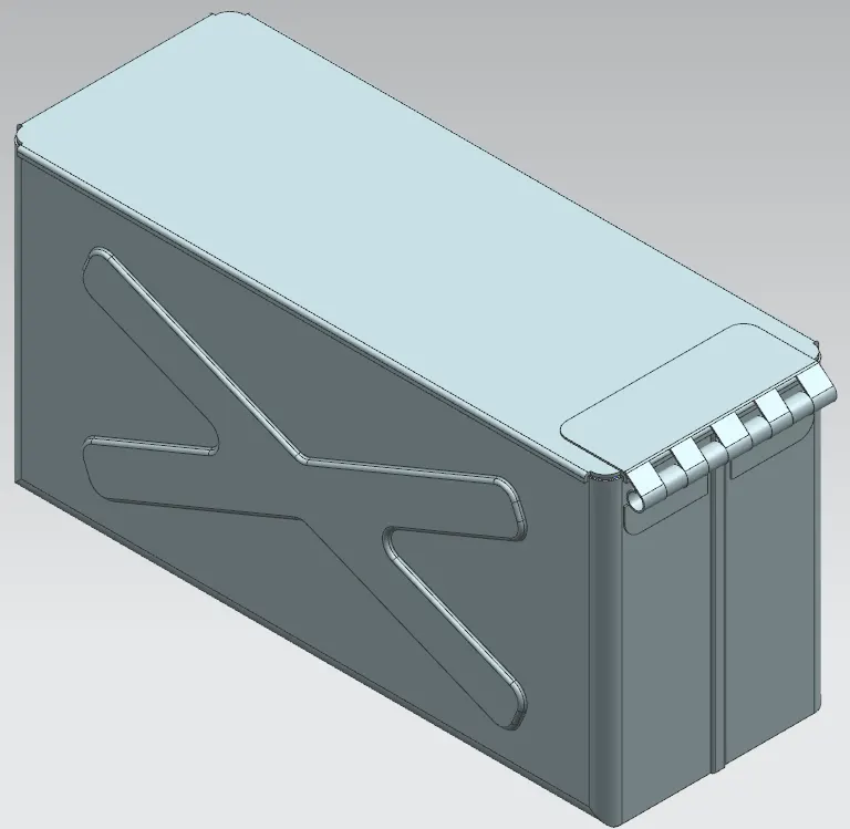
43 - Draft sheet of lid . -
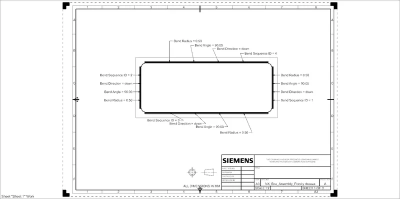
44 - Draft sheet of hinge 1 . -
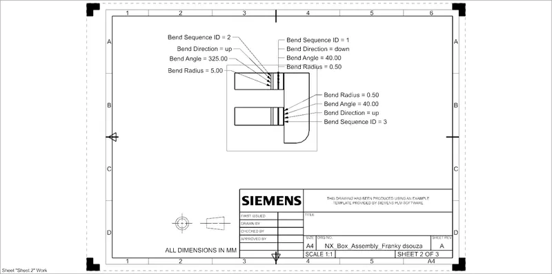
45 - Draft sheet of hinge 2 -
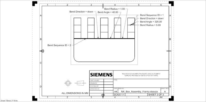
DESCRIPTION-
1 - TAB COMMAND - 
This command is used to create a base feature by extruding sketch along vector by a certain thickness value or by adding material to existing faces and bend regions of sheet metal parts .
2 - NORMAL CUTOUT - 
This command is used to cut material by projecting a sketch onto a model and then cutting perpendicular to the faces intersected by projection .
3 - BEND - 
This command is used to bend the material using a sketch as input line for bend . bend is given considering the K factor , bend radius .
4 - FLANGE - 
This command is used to add a flat flange at an angle to planar face and add a bend between the two .
5 - BREAK CORNER -
This command is used to round or chamfer sharp corners of tab or flange .
6- UNBEND - 
This command is used to unbend the material to create a flat sheet .
7 - CLOSED CORNER - 
This command is used to modify two flanges , it closes the corner of two flanges where they meet . relief can also be given to the flanges .
8- HEM FLANGE - 
This command is used to modify the edge of sheet metal part by folding it onto itself , this is done to increase the stiffness of part and also it is done for safe handling purpose .
9 - MIRROR BODY - 
TThis command is used to mirror the entire body part along a plane .
10 - DIMPLE -
This command is used to create an identation in sheetmetal part using sketched section as input for dimple . it can lift the area of model inside a sketch that simulates a stamping tool .
11 - BEAD - 
This command is a stiffening deature . it stiffens the sheetmetal . it is used to lift the material along contour of sketch that simulates stamping tool .
12 - MIRROR FEATURE - 
This command is used to mirror or duplicate a part along a plane.
13 - REBEND - 
This command is used to bend the sheetmetal part that we had previously bend .
14 - FLATPATTERN -
This command is used to create the 2D drawing view of the sheet metal part .
15 - DRAFTING - 
This command is used to create drafting or detailed drawing of a part.
16 - UNITE - 
This command is used to combine two or more bodies into a single body .
CONCLUSION-
We have successfully created a box_assembly using the tools in sheetmetal workbench of Nx cad . we have learnt about various tools during this process .