Week 8 - Challenge 1 - Base Bracket Design
WEEK 8 CHALLENGE-1
BASE BRACKET
Aim
To Create the Base Bracket Plastic component from the given Class A Surface.
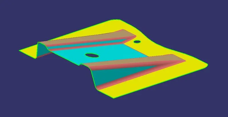
Pic.1 (Given Class A Surface)
Steps to perform given task
- Create Tooling axis and perform draft analysis for given model.
- Create Class B Surface from class A Surface.
- Create Class C Surface.
- Create a solid body using close surface command.
Create Tooling axis:
Class A surface is one which is provided to us, check the connectivity of the Class A Surface ensure that there is no gap between the component, using join command.A tooling axis is created at the center of hole of the class A surface using line definition and point, the tooling axis is nothing but the mold opens or cavity opens.
- Create dummy tooling axis by taking any hole or simple structure as reference.
- Create a intersection between the part and a plane ( Drafting can be expected to be difficult )
- Taking any two lines which might create problem for tooling direction , a line is created coinciding these lines.
- Bisecting line is created between these two lines.
- The bisecting line is taken as Actual Tooling axis.
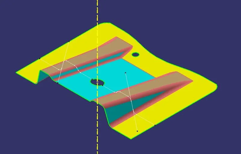
Pic.2 (Tooling Axis)
Perform draft analysis:
Draft Analysis
For molded or cast parts, the draft angle is the amount of taper perpendicular to the parting line. It is measurable in degrees. Because plastic shrinks and sticks on molding surfaces as it cools, we draft the walls of the plastic part so that it ejects or breaks free from the molding surfaces more easily and without dragging. To reduce the risk of damage to the parts and ensure ejection, a functional injection molding part must have drafts on both the cavity and core sides.It is performed using tooling axis as tooling direction and Minimum draft angle considered is 3 degree.When the value obtained is less than 3 it will be highlighted in red, These regions drafting is impossible .Hence Tooling axis should be changed or additional process is to done to produce the part.
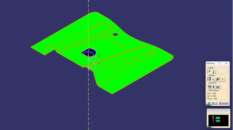
Pic.3 ( Draft Analysis)
Create Class B Surface from class A Surface:
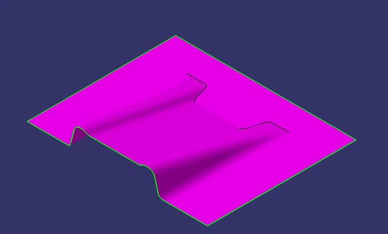
Class B surface is created by extracting the surface from the class A and Surface untrim then offsetting that surface according to the required thickness( which is 2.5mm for given part). the extracted surface should be little bigger than the original class A surface which can be done by using extrapolating command which increases the size of the boundary.
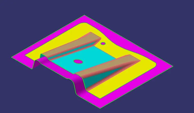
Pic.4
Pic.5
Create Class C Surface:
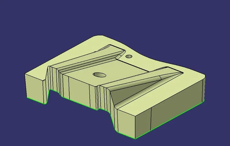
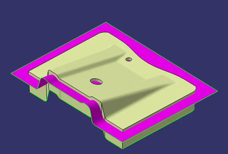
The surface that Joins both Class A and Class B surface is considered to be Class C Surface.It is created by using Sweep command which created a suface according to the selected boundary.Then,It is trimmed according to the thickness of the part or till the B surface using Trim command which cuts the excess or unwanted areas to the selected point.
Pic.6
Pic.7
Pic.8
Create a Solid body using close surface command:
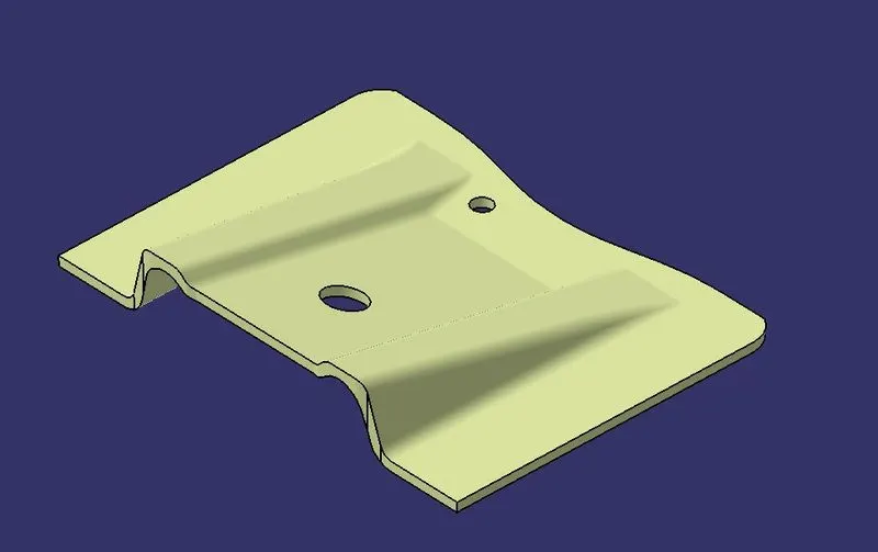
Creating a solid body from the final result that we get after trimming the Class C Surface using the closed surface command which makes a solid surface between the closed surface.
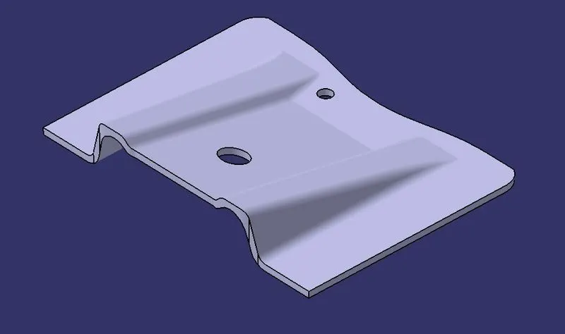
Pic.9
After the conversion of the Closed surface into a Solid Part, it is subjected to Draft analysis to check if the Part can be manufactured using the Molding process and meets all the Injection molding requirements.
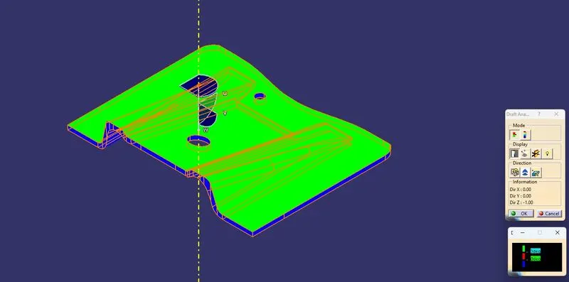
Pic.10
Tree Structure:
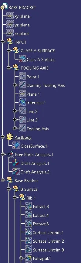
Pic.11
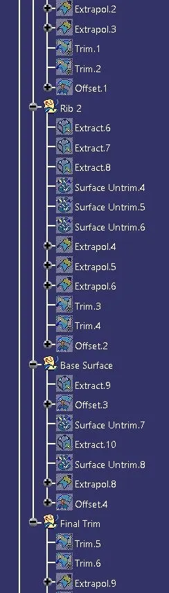
Pic.12
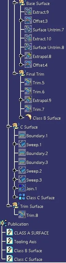
Pic.13
Publication:
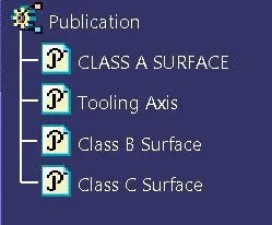
Pic.14
Different Views:
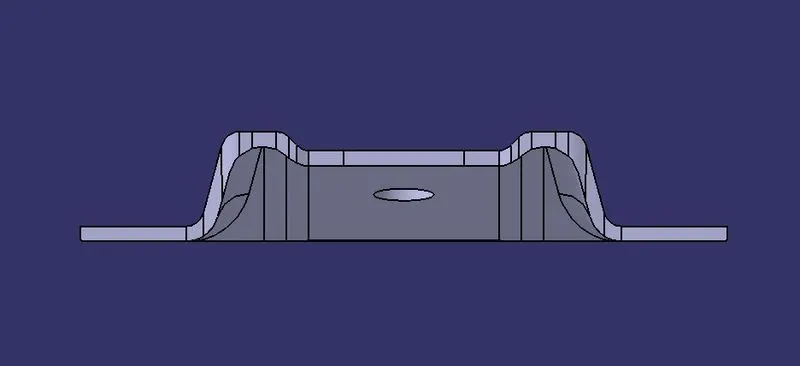
Pic.15 (Front View)
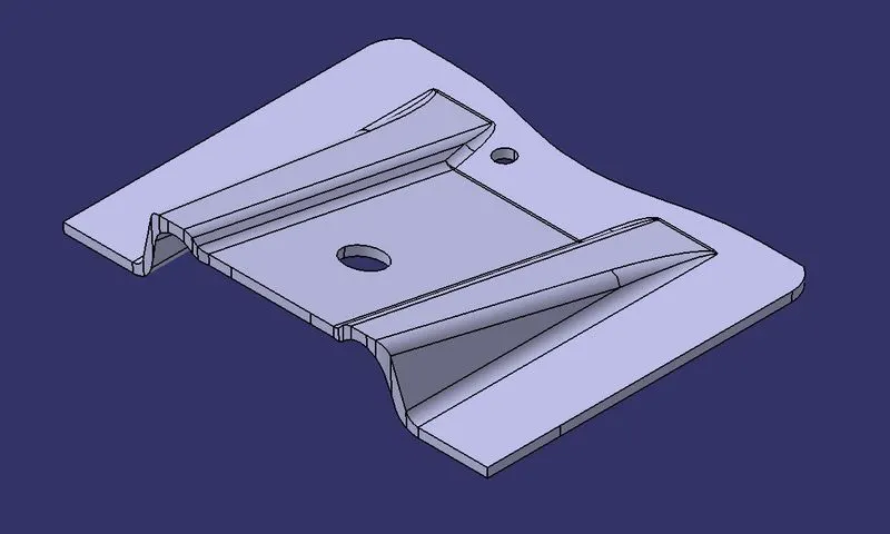
Pic.16 (Isometric View)
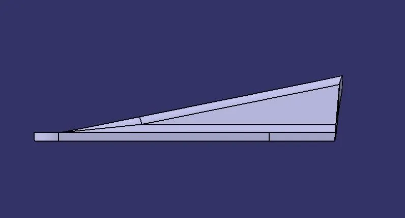
Pic.17 (Side View)
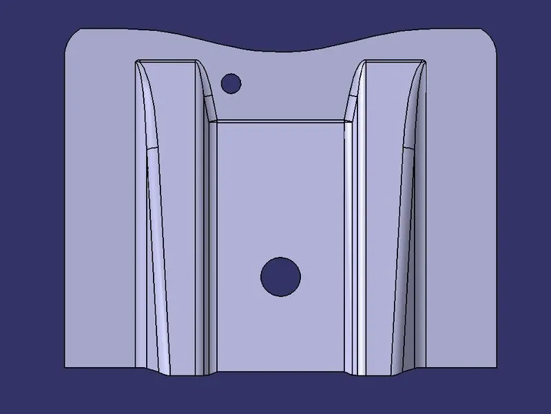
Pic.18 (Top View)