Week 9 - Project 1 - Door Trim Lower with Engineering Features
WEEK 9 CHALLENGE - 3
PROJECT-1
DOOR TRIM LOWER WITH ENGINEERING FEATURES:
Aim
To create Heat Stakes & Locators for the Door Trim from the the Class A component.
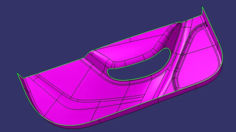
Pic.1 (Given Class A Surface)
Steps to perform given task
- Create Tooling axis.
- Create Class B Surface from Class A Surface.
- Create Class C Surface.
- Create a solid body using close surface command.
- Create 4 Way Locators
- Create Heat stakes with supporting Ribs.
- Perform draft analysis for given model.
Create Tooling axis:
Generally,Tooling axis is created using Bisecting line method.But in this challenge we use another method to create the tooling axis,First select the Class A Surface then using Measure inertia command select Create Geometry then a small window will pop up from there select Associative Geometry then Centre of Gravity.Now make a line at point using Point-direction through ZX Plane direction.Now,performed a draft analysis check from that line whether the created tooling axis is in the correct position or not. If, in the draft analysis check the surface highlighted with green colour on both sides of the surface the tooling axis is in the correct position and direction.
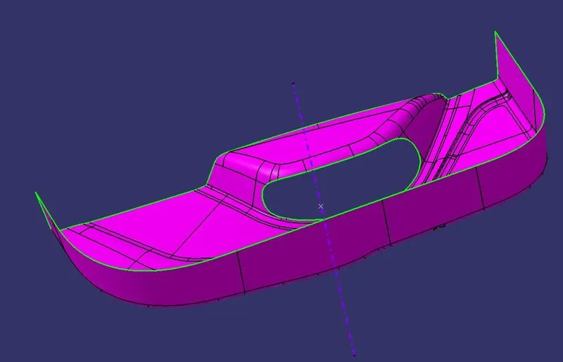
Pic.2 (Tooling Axis)
Draft analysis for class A surface:
To perform the draft analysis in class A,selected the featured draft analysis tool in the Generative shape design workbench.Before drafting we have to make sure that in the view mode it is selected for the materials.
After selecting the feature draft analysis tool we drag the compass from its position to
the tool axis. Then lock the compass. After that select anywhere on the component and
it will give you the result.
We change the minimum draft for the component to 3°.
We can use the running point option to check the angle of the component.Y direction
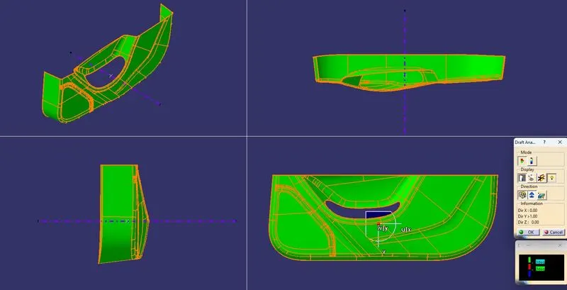
Pic.3 ( Draft Analysis for Class A)
Create Class B Surface from class A Surface:
Class B surface is created by offset the class A surface inside as per our thickness requirement (thickness is 2.5mm)So,offset the class A to 2.5mm inside. Once the offset is created, we can observe some patches on the offset surface by taking the boundary for the offset surface, those patches are formed due to the fillets on the class A surface.To cover all these Patches, we will use the JOIN command in which uncheck the CHECK CONNEXIVITY and in SUB-ELEMENTS TO REMOVE option we will select the filleted surface to remove and click OK. We will do the same for all PATCHES REGION.After removing the filleted surface, we will disassemble the surface body by using the DISASSEMBLE command. Once the 2 surface domain created we will create the BOUNDARY curve for both surfaces.Then,creating the boundary curves, we will use EXTRAPOLATE command to extend the surfaces till the intersection then we will use the TRIM command to remove the extra surfaces and they will be joined together automatically.Same procedure is followed for all patches.
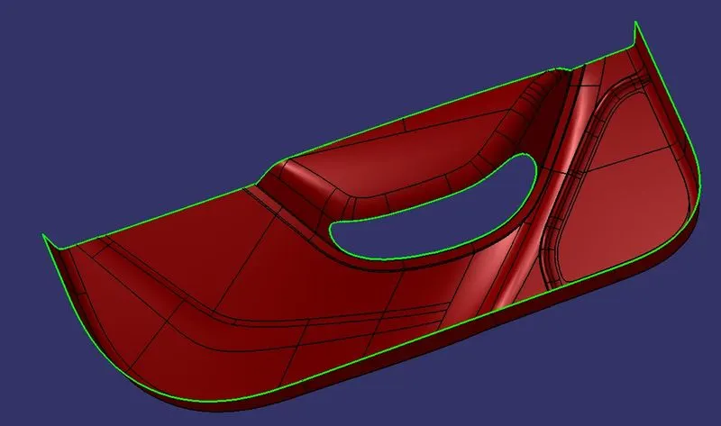
Pic.4 (Class B)
Create Class C Surface:
To create the class C surface concerning the boundary of the class A surface, used the Sweep command. Initially, extracted the boundary of the class A surface with Point continuity, and sweep the extracted boundary concerning the surface at 90deg (for draft angle) for 9 mm to intersect properly with the class B surface.We've to create two Class C Surfaces, one is for the outer surfaces and the other is for the Inner Cutting region.
Once we sweep all the surface boundaries of class A, extrapolate the sweeped surfaces until both surfaces got intersected properly, and trim them to remove extended extrapolated surfaces to get a proper sweep boundary throughout the entire surface, including the centre inner cutting region of the Door trim Lower.
Now, join both class A and sweep boundary to get the complete class C surface.
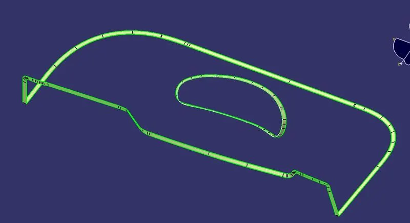
Pic.5 (Class C Surface)
Final Trim:
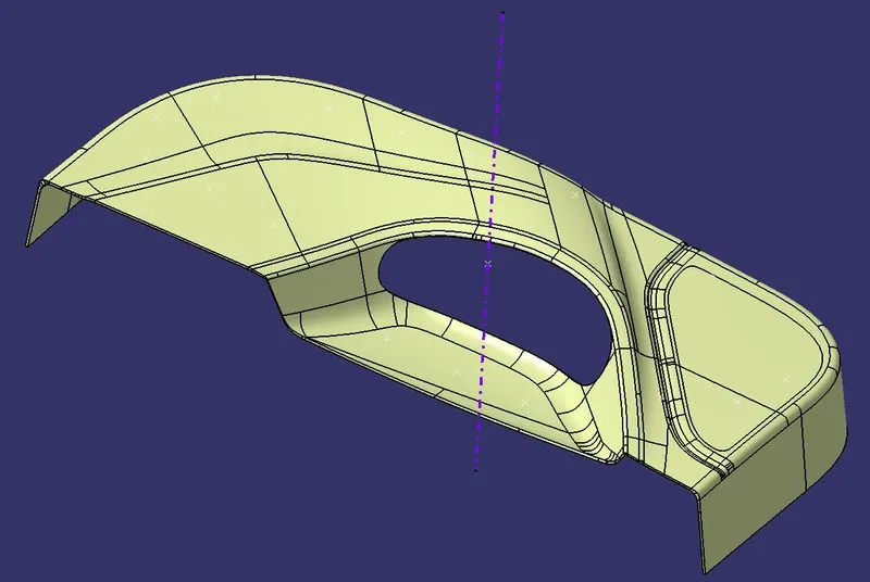
Pic.6
Creating Solid body:
To create the solid body I used the closed surface command in the part workbench. Click on the closed surface command in the part workbench and give the closed surface as an input to create the solid part body.
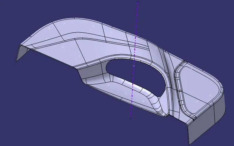
Pic.7
Create Locator:
To create the locators, created a sketch of 15mm of 2 lines on the body. After creating the sketch, pad it 26mm in height and thicken it to 1.4mm and I drafted it with 0.5deg in the direction of the tooling axis. I gave 3mm of chamfer with 45deg of inclination and after I gave a fillet of 0.3mm radius. Then,Copy Paste 4 Way Locator to Translate it.Use point to point Translation for second 4 Way locator.Then Union Trim both Locators with Main Body.
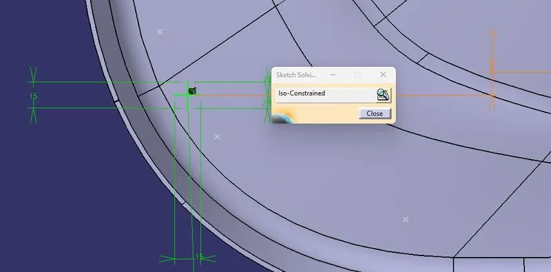
Pic.8 (Iso-constrained )
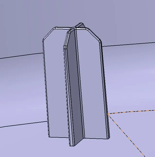
Pic.9 (Locator)
Create Heat Stakes with Supporting Ribs:
To create the heat stakes .Create a sketch of 2 circles with diameter 5mm and 7mm respectively on the surface. After the creation of the sketch, pad it gave a draft angle of 0.5deg on both sides with toolinga s pulling direction.and give fillet of 0.3mm. then,draw another sketch of 2 lines of 15mm and pad it to height and 1.4 mm in thickness. After padding the ribs, drafted 0.5deg in the tooling axis direction and filleted it with a radius. Finally, union trim the ribs with a heat stake to remove the ribs, which are present inside the heat stakes.
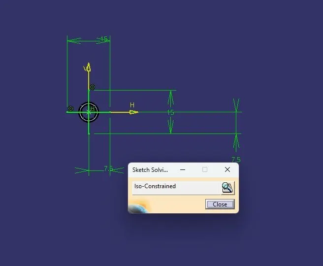
Pic.10 (Heat Stakes Iso-contrained)
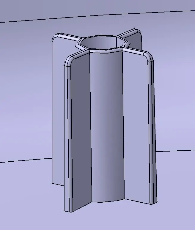
Pic.11 (Heat Stakes with supporting Ribs)
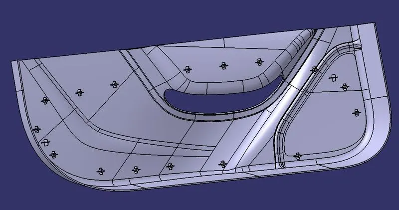
Pic.12 (Door Trim with Heat Stakes & Locators)
Draft Analysis for the Solid Body:
To perform the draft analysis for the solid part body (which has Heat Stakes & Locators on it),used the featured draft analysis tool in the generative shape design workbench. Initially,aligned the compass to the tooling axis and selected the solid part body in the colour bar 0.49deg draft angle provided .The areas which highlighted in Green the below image are cleared in the 0.49deg draft angle.
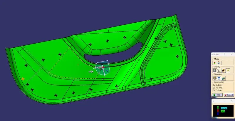
Pic.13 (Draft Analysis )
Differtent Orientation :
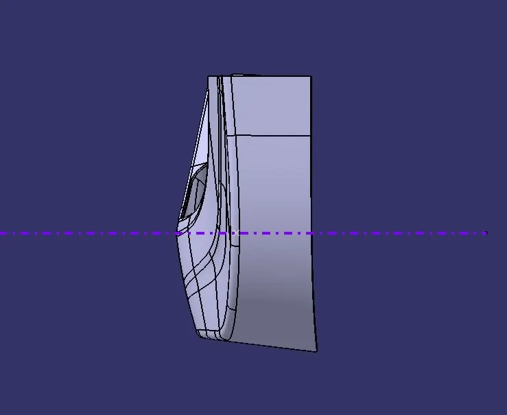
Pic.14 (Front View)
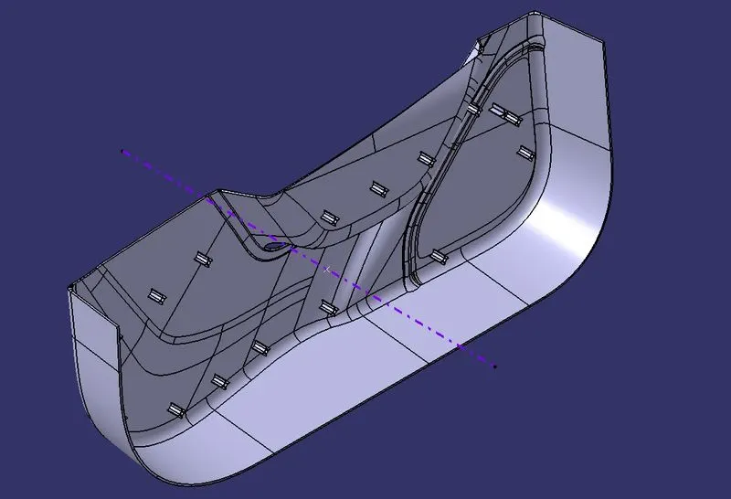
Pic.15 (Isometric View)
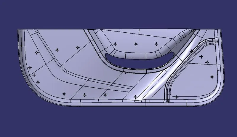
Pic.16 (Side View)
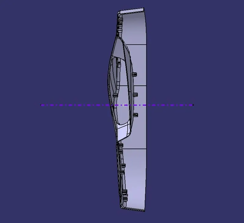
Pic.17 (Top View)
Tree Structure :
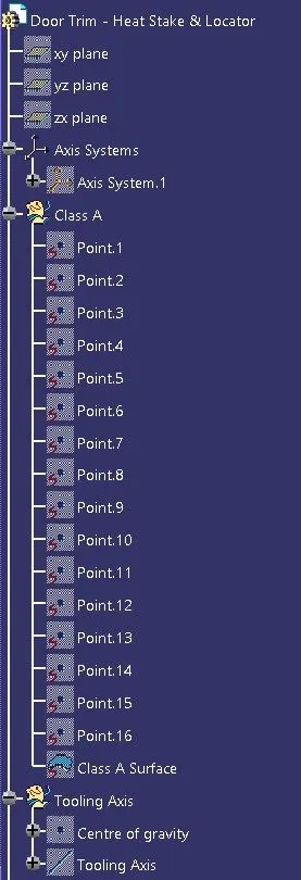
Pic.18
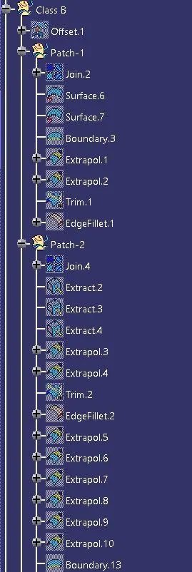
Pic.19
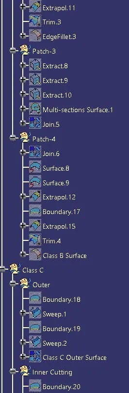
Pic.20
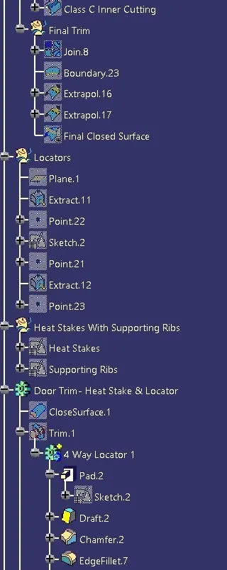
Pic.21
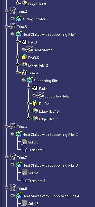
Pic.22
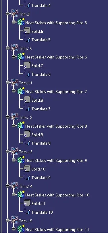
Pic.23
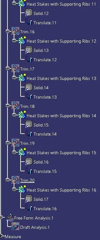
Pic.24
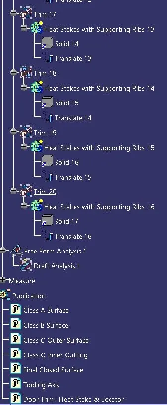
Pic.25
Publication :
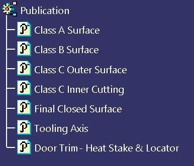
Pic.26