Radar Mast & Final Assembly of Yacht
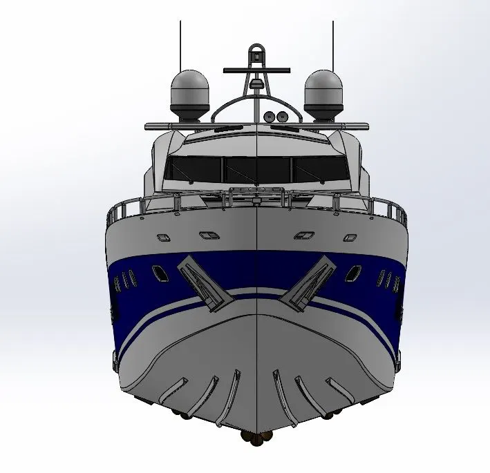
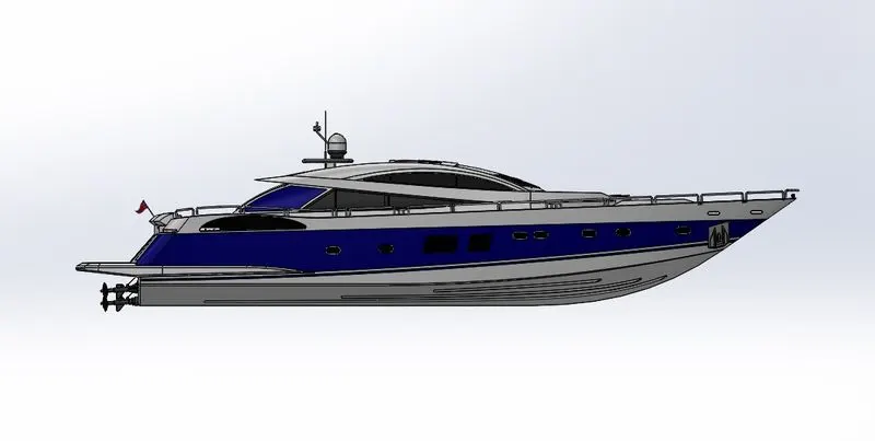
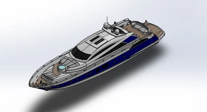
MODELING AND ASSEMBLING OF SUNSEEKER PREDATOR YACHT
INTRODUCTION
This report explains about the Modeling and Assembling of Sunseeker Predator Yacht using Solidworks 3D Modeling software.It also explains every steps from initial sketch to final rendering using different tools,features etc.
OBJECTIVES
The main objective of this designing is to obtain practicle knowledge in Solid part modeling and surface modeling.
- In the process of modeling a sun seeker predator yacht we design a part or model by using initial 2D sketches, and then we turn them into 3d models using the tools like surface tools, featuring tools etc.
- Get well knowledge in solidworks interface and make custom shortcuts of tools ,tool bar , command manager commands.
- Detail designing of each components of chopper with sketch dimensions.
- Assembly of designed parts with proper relations of all part models.
- Go well with using Decals, Lights, Appearance, Environment, Backplates.
- Obtain Knowledge in Solidworks Visualize Rendering tools to make realistic render of the modelled predator yacht.
PART MODELING
Part modeling is the process of which modeling of a component in 3D by using the 2D Sketch using tools, sketch constraints and features etc.
METHODOLOGY
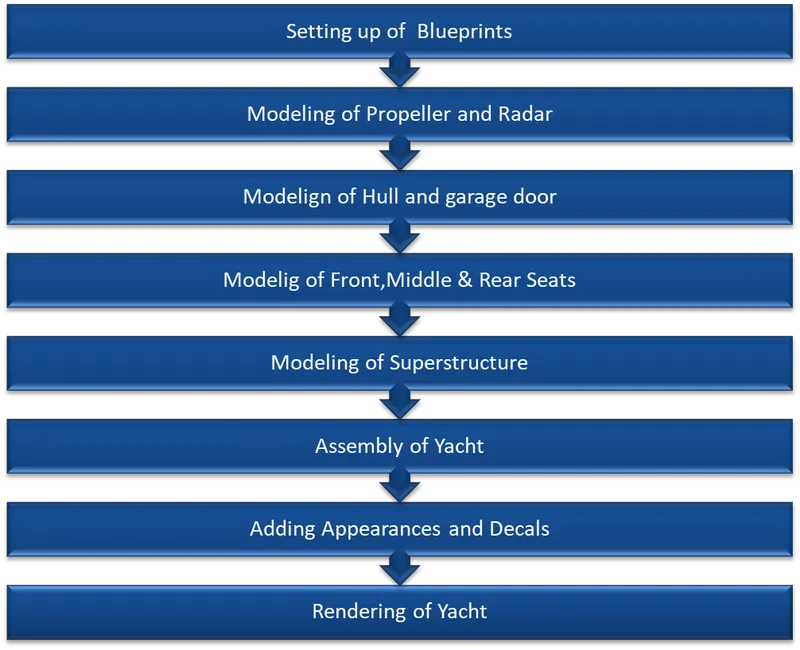
COMPONENTS TO BE DESIGNED
- Propeller
- Radar
- Hull
- Garage door
- Front Seat
- Middle Seat
- Rear Seat
- Superstructure
- Radar Mast
PROPELLER
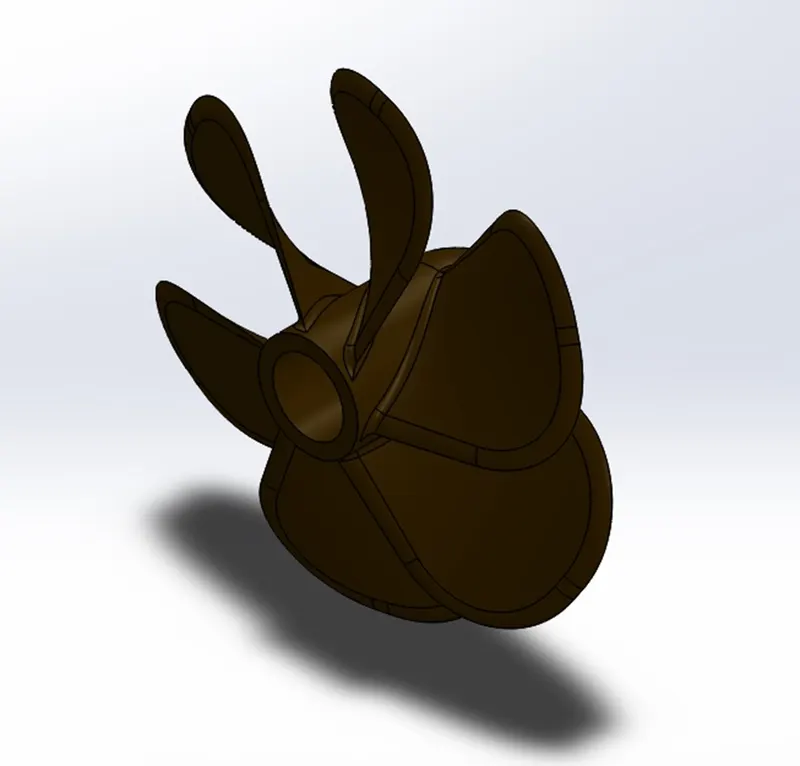
The solid component, consisting of a hollow cylinder of a certain thickness, has fan blades mounted over the outer surface of the cylinder is called a propellor. The main function of the propeller is to exert thrust by rotating of fan blade under the water so that the yacht can move forward.
- For designing the propeller the main hub is created by simple sketch line and spline drawn on the front plane and extruded using the revolve option around the centre line.
- The wings are twisted parts created by sketching the two different rectangles on two different surfaces and formed into solid using loft option.
- The shape of the wings are obtained fillet applied at the two edges on top side.
For inserting the shaft the hole is created by sketching the circle on the hub back end and material is removed using extrude cut option .
COMMANDS USED TO MODEL
In Sketch :
Spline
Circle Line
In Features :
Revolved Boss Base
Lofted Boss Base
Extruded Cut
Reference Plane
Circular Pattern
Fillet
Pic.1
RADAR
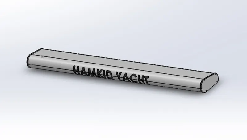
Radar is a navigation tool used in yachts. Radio detection and ranging (RADAR) helps ships to detect objects far away by using radio waves. It is very useful in bad weather for navigation. It sends radio waves in all directions and when the signal hits an object then its info is displayed on the screen. Hence the pilot can steer away to avoid any collision or accident.
- Radar was modeled by using solid features such as Revolve Boss/Base, Extrude cut, etc.
- The fillet feature is used to remove all sharp edges.
- As the Radar is symmetric in shape. Therefore, half part was modeled and the other half was mirrored using the Mirror feature and both solids were merged in the operation.
- Later the text is added to the Radar to give it a realistic look. The text was projected on the surface of the radar using the Split Line feature.
COMMANDS USED TO MODEL
In Sketch :
Line
Text
Circle
Point
In Features :
Extruded Boss/Base
Extruded Cut
Sketch Pattern
Fillet
Mirror
Split Line
Pic.2
HULL
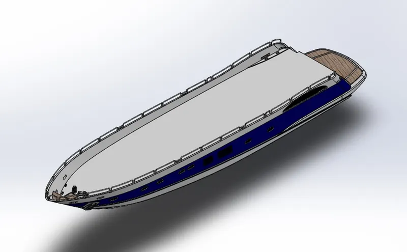
Hull is a bottom floating body of a yacht that meets the water line below and is open above. Surface modeling was used to model Hull. I used project curves, surface extrudes, trim surface, lofted surface, knit surface, and other surface and solid features to design a yacht from a 2-D to 3-D model. First, we created Blueprints from different planes then we created 2-D sketches and converted 2-D to 3-D by using surface features. Then we created a solid body from the surface body and knitted together the different components of the hull. Only half portion of the hull was modeled and the other half was mirrored using the mirror feature as it is symmetric. Fillets were used to eliminate sharp edges and give them an aesthetic appeal. The appearance was given for a realistic look.
The intermediate member of the hull consists of girders, webs and stringers. Depending on the structural arrangements, there may be longitudinal members for strengthening purpose.
COMMANDS USED TO MODEL:
In Sketch:
Line
Spline
Circle
Rectangle
Arc
Slot
3-D Sketch
Sketch picture In Surfaces:
Extruded Surface
Revolved Surface
Lofted Surface
Surface Trim
Surface Fill
Surface Knit
Delete Face
In Features:
Project Curve
Chamfer
Fillets
Reference Plane
Split :
Split Line
Extruded BossBase
Extruded Cut
Mirror
Pic.3
GARAGE DOOR
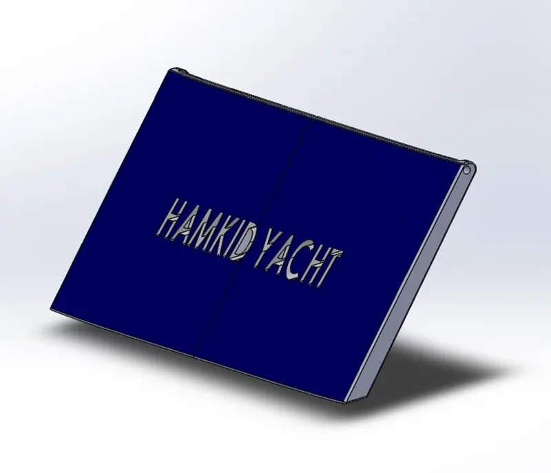
A garage door is a large door on a garage that opens either manually or by an electric motor la garage door opener). Garage doors are frequently large enough to accommodate automobiles and other vehicles. The operating mechanism is spring-loaded or counterbalanced to offset the weight of the door and reduce human or motor effort required to operate the door. Less commonly, some garage doors slide or swing horizontally, Doors are made of wood, metal, or fiberglass, and may be insulated to prevent heat loss.
COMMANDS USED TO MODEL :
In Sketch :
Line
Spline
Circle
Text
In Features :
Extruded Cut
Reference Plane
Fillet
Shell
Mirror
Pic.4
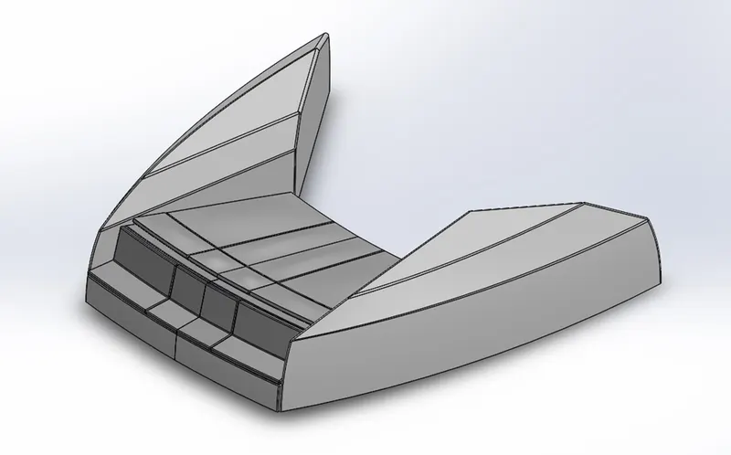
FRONT SEAT
Front seats feature two connected seats that are built back-to-back from one and other. They have a built-in storage unit undemeath them. Lounge seats can also fully recline right back to make it easier for you to kick your feet up and get more comfortable. The front seat in our model was placed before the superstructure and also it has sun pads to rest on it. Sun pads are a great way to reclaim lost space on our boat.
COMMANDS USED TO MODEL
In Sketch
Sketch Picture
Line
Spline
Circle
Arcs
In Surfaces
Extruded Surface
Lofted Surface
Trim Surface
Filled Surface
Knit Surface
Swept Surface
Revolved Surface
In Features:
Extruded Cut
Revolved Boss/Base
Chamfer
Fillet
Mirror
Dome
Pic.5
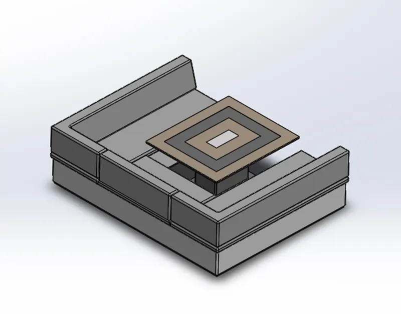
MIDDLE SEAT:
The middle seat in our model was placed just behind the superstructure it is provided with a luxury table to dine out. It can also be used to have casual meetings with co-passengers.
COMMANDS USED TO MODEL
In Sketch
Sketch Picture
Line
Rectangle
In Features
Extruded Boss/Blasé
Chamfer
Fillet
Mirror
Reference Plane
Pic.6
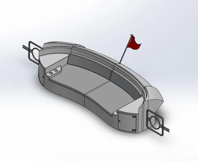
REAR SEAT
The rear seat was placed at the end of the deck surface. The rear seat consist of locker racks and steel doors for our stairs. The flag was also placed behind the rear seat since it's the end part of our yacht. To have a nice view from the yacht while having a drink the rear seat was also provided with a slots to rest the glass or mug.
COMMANDS USED TO MODEL
In Sketch:
Sketch picture
Spline
Circle
arcs
Line
Rectangle
In Surfaces
Swept Surface
Extruded Surface
Off-set Surface
Filled Surface
Knit Surface
Ruled Surface
Lofted Surface
In Features
Reference Plane
Extruded Boss/Base
Revolved Boss/Base
Fillet
Mirror
Pic.7
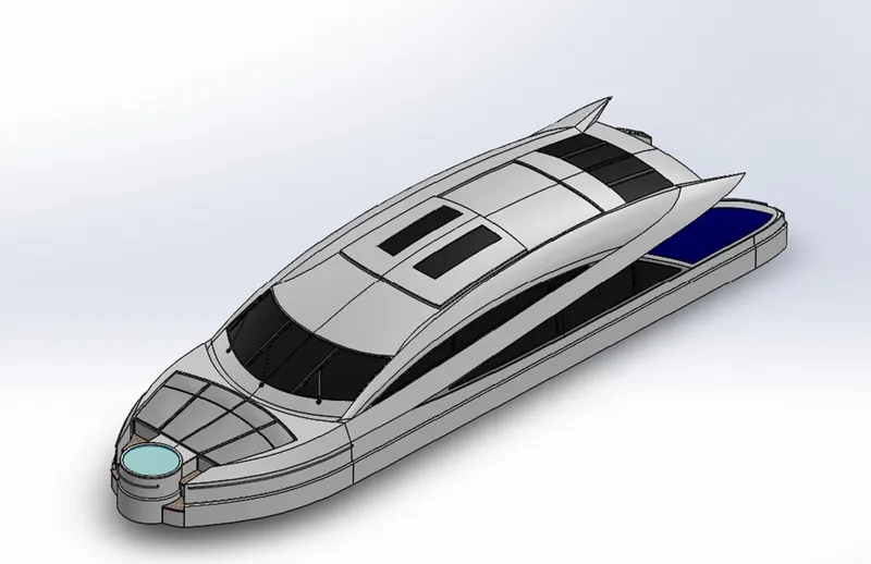
SUPERSTRUCTURE
A superstructure is an upward extension of an existing structure above a baseline called ground level and it usually serves the purpose of the structure's intended use. A superstructure is a decked structure on the freeboard deck, extending from side to side of the ship.
COMMANDS USED TO MODEL
In Sketch :
Sketch Picture
3D Sketch
Line
Spline
Circle
Rectangle
Center Point Arc
In Surfaces :
Extruded Surface
Swept Surface
Ruled Surface
Knit Surface
Trim Surface
Extend Surface
Filled Surface
Lofted Surface
Revolved Surface
Fillet
Chamfer
In Features
Project Curve
Reference Curve
Convert Entities
Split
Split Line
Pic.8
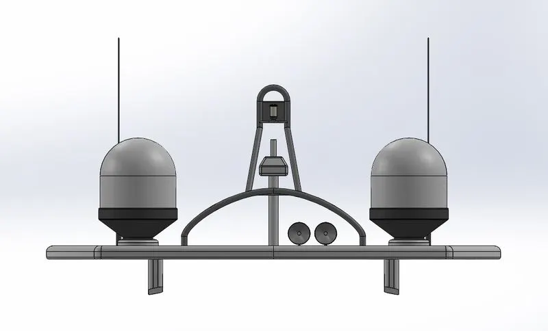
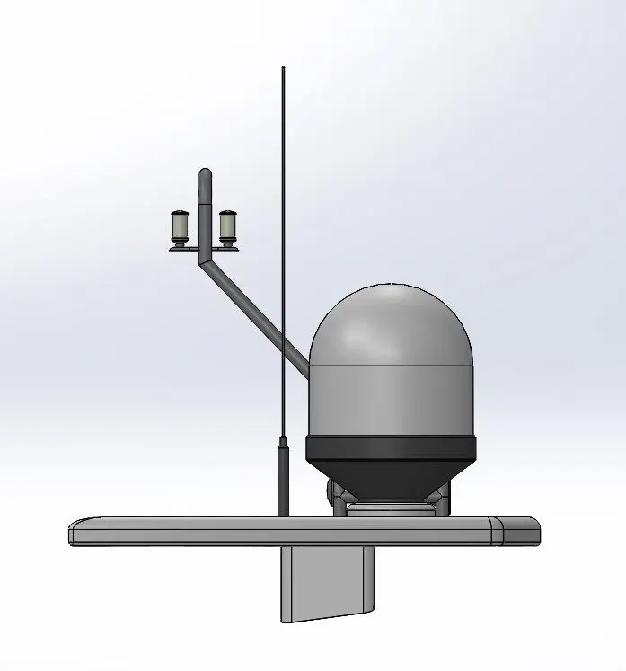
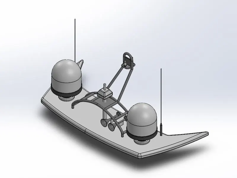
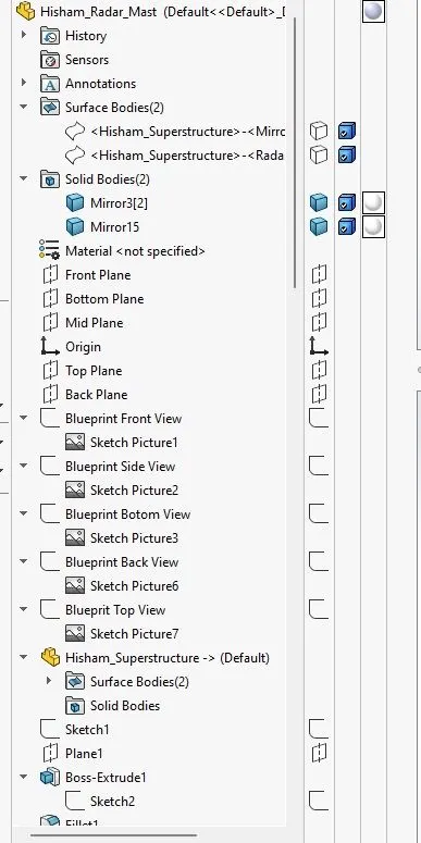
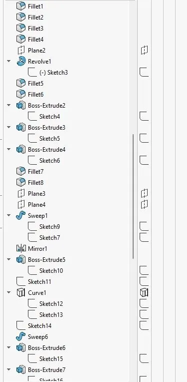
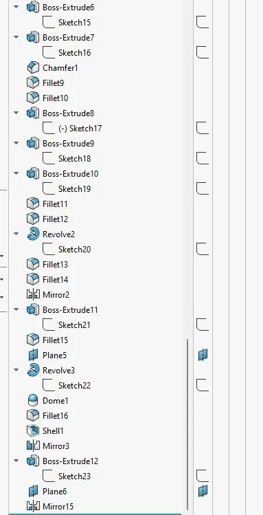
RADAR MAST
A mast is a vertical ship structure mounted on top of bridge and forward of the forecastle towards the ship's bow. It accounts for the support platform for the ships derrick and hold necessary equipment's such as radars, navigation light and ships horn in case of foremast. They are made of high tensile steel with added rigidity based on the size of derricks it holds Other than that a ships main mast is also used to hoist ships flag Out of different parts of ship the main job of mast is to hold necessary equipment such as radar receiver, navigation lights, ships horn, flags and derricks in some case.
COMMANDS USED TO MODEL :
In Sketch
Sketch Picture
Line
Spline
Rectangle
Arcs
In Feature
Extruded Boss/Base
Lofted Boss/Base
Revolved Boss/Base
Swept Boss/Base
Reference Plane
Projected Curve
Fillet
Mirror
Dome
Shell
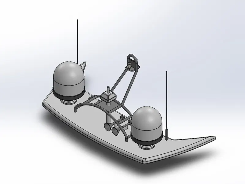
Pic.9
Feature explained
- Extruded Boss/Base:
Extruded boss/base feature is used to make a sketch into a complete solid model or part. This feature contains option such as “From to Direction” to select the direction in which we want to extrude our part. “Dimension” column to get the required the length of our mode.
- Revolved Boss/Base:
To get a cylindrical object, we use Revolved Boss/Base feature in our fully defined sketch. As in Extruded Boss/Base feature we got “Axis of Revolution” to give the axis or plane in which we wish our model to revolve. We also got the direction tab to give the direction for our model.
- Extruded Cut:
If we want a hollow space in our model, we can do it by using the Extruded cut feature. This feature requires a proper fully defined sketch with closed entities. When we click on this feature, the property manager window will pop-up with an option similar to Extruded boss/base feature. It got “From and To” to give the feature from where it has to cut our model. And the direction in which it has to cut is given in the “Direction” section available.
- Extruded surface:
Extruded Surface feature is used to create an extruded surface of the sketch. Unlike Extruded Boss/Base, Extruded surface feature creates a surface which is not a closed one.
- Fillet:
Fillets are the most important and frequently used features in making a model as it has got many advantages. Once we made a solid part, it will have sharp corners and edges which we do not like to have. So, to make the sharp edges/corners to look smooth and have nice finish, we use this “Fillet” feature. The thickness of the fillet can be adjusted in the property manager window pop-up.
- Linear Pattern:
Linear pattern is used make a copies/duplicates of the feature which we want in our model, in the linear direction. It is an easy feature which let us do same the process for n number of times, without adding any extra sketches.
- Mirror:
Mirror feature is used to mirror/copy the object, features in our model. When the feature is applied the property manager window will pop-up asking you the axis or plane in which you want your feature or object to get mirrored or copied. You can also select multiple features.
- Reference Geometry:
It is used to define a sketch or feature in an appropriate plane or axis. It is also used create a plane of our desired requirement to create a sketch on that plane and then get our model in desired position.
- Knit:
Knit is a feature which is used to bind/combine two or more faces and surfaces into a single body. It creates a closed body by filling or closing the gaps in between the edges.
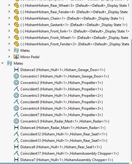
- Mates:
Mates is the feature which you can see and use during the assembly of our parts into complete model. It creates a geometric relationship between two parts. When we apply mate, it defines linear or rotational motion to the parts to get it fixed at the right position with the other part. There are many mates which we can apply to the models.
- Coincident mate: coincident mate allows us to make two planes into coplanar. When we apply this mate, the part cannot be removed separate from the plane.
- Tangent mate: Tangent mate is used to place the part and the plane in a tangent relation.
- Concentric mate: Concentric mate is used to make the circular faces to be concentric and allow them to move along the axis.
- Angular mate: Angular mate is allowed to make the part to be fixed at a certain angle with the flat surface.
Decals:
A decal consists of a picture, image, pattern, or design that’s printed on a metal body. We have added decals on Hull surface, Jacuzzi stairs. It gives nice appearance to the yacht.
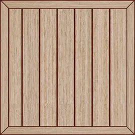
Pic.10
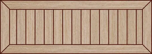
Pic.11
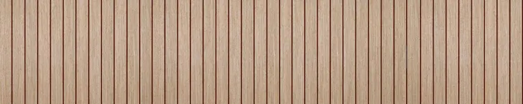
Pic.12
ASSEMBLY OF YACHT
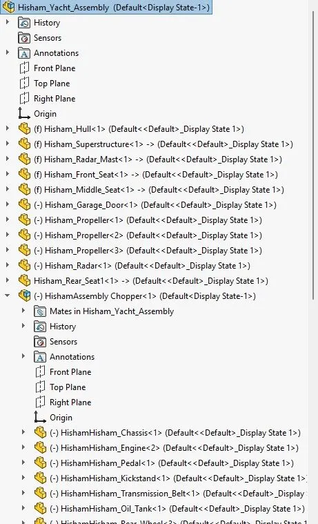
An assembly is a document in which parts, features, and other assemblies (sub-assemblies) are mated together. The parts and subassemblies exist in documents separate from the assembly. For example, in an assembly, a piston can be mated to other parts, such as a connecting rod or cylinder. This new assembly can then be used as a sub-assembly in an assembly of an engine. The extension for a SolidWorks assembly file name is SLDASM.
PROCEDURE:
- Import all the parts manually by using Insert Components option
- Then fix the Hull part by applying the coincident mate to the Top, Right and Front planes of the Assembly and Hull respectively.
- Then for each part apply the necessary mates required by the Blueprint using Coincident mates. Angle Mates Distance mates etc.
- Advanced mate was also used wherever required.
COMMANDS:
Smart Mate-A Smart mate is an assembly mating relation that is created automatically.
Mate-Amate is a geometric relationship, such as coincident, perpendicular,tangent, and so on, between parts in an assembly.
Mate group - Amate group is a collection of mates that are solved together.The order in which the mates appear within the mate group does not matter.
Sub-Assembly - A sub-assembly is an assembly document that is part oflarger assembly. For example, the steering mechanism of a car is a subassembly of the car.
Insert Components -We can insert multiple instances of the group of components without closing the Property Manager.
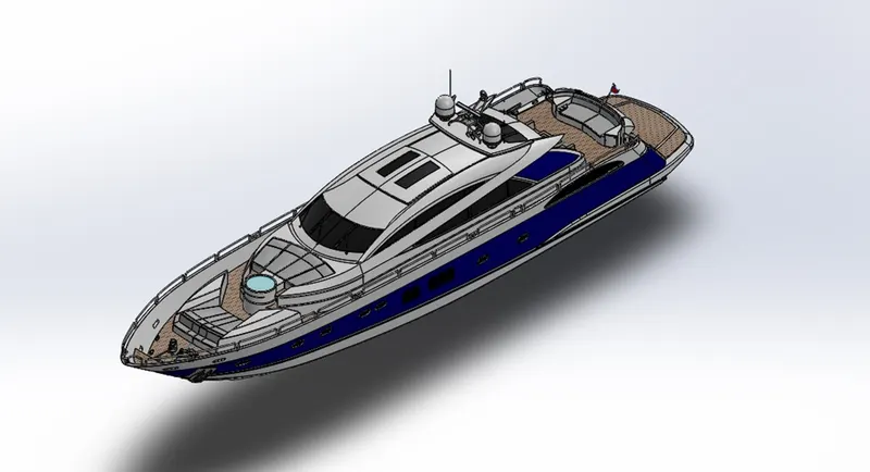
Pic.13
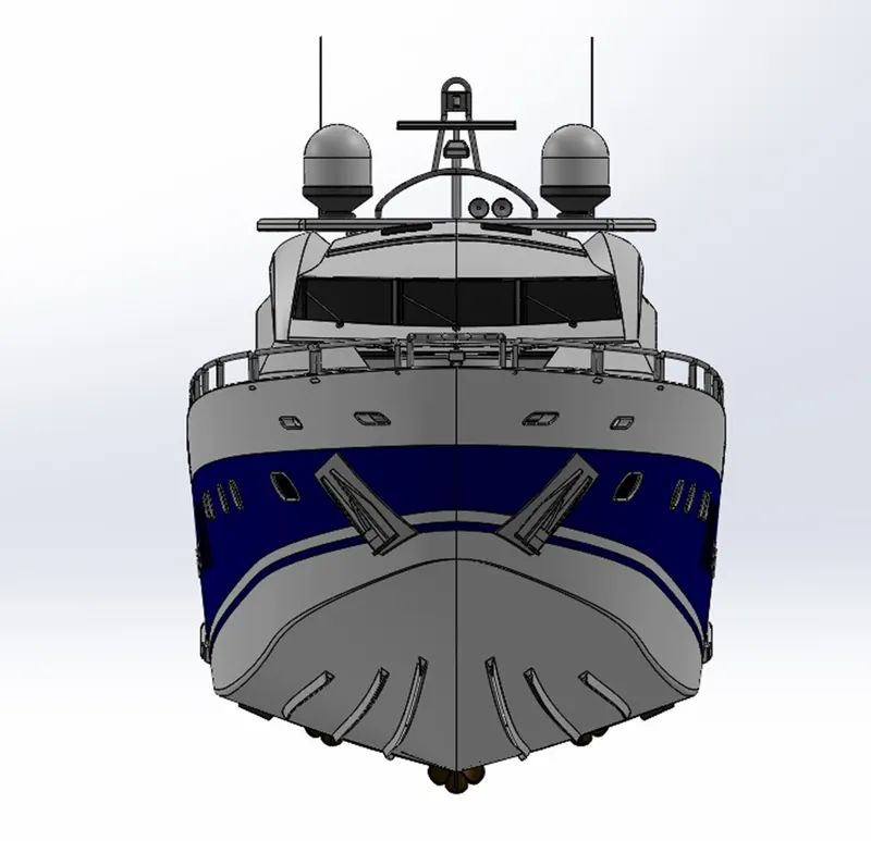
Pic.14
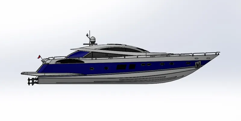
Pic.15
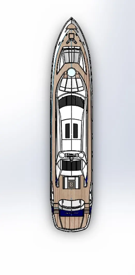
Pic.16
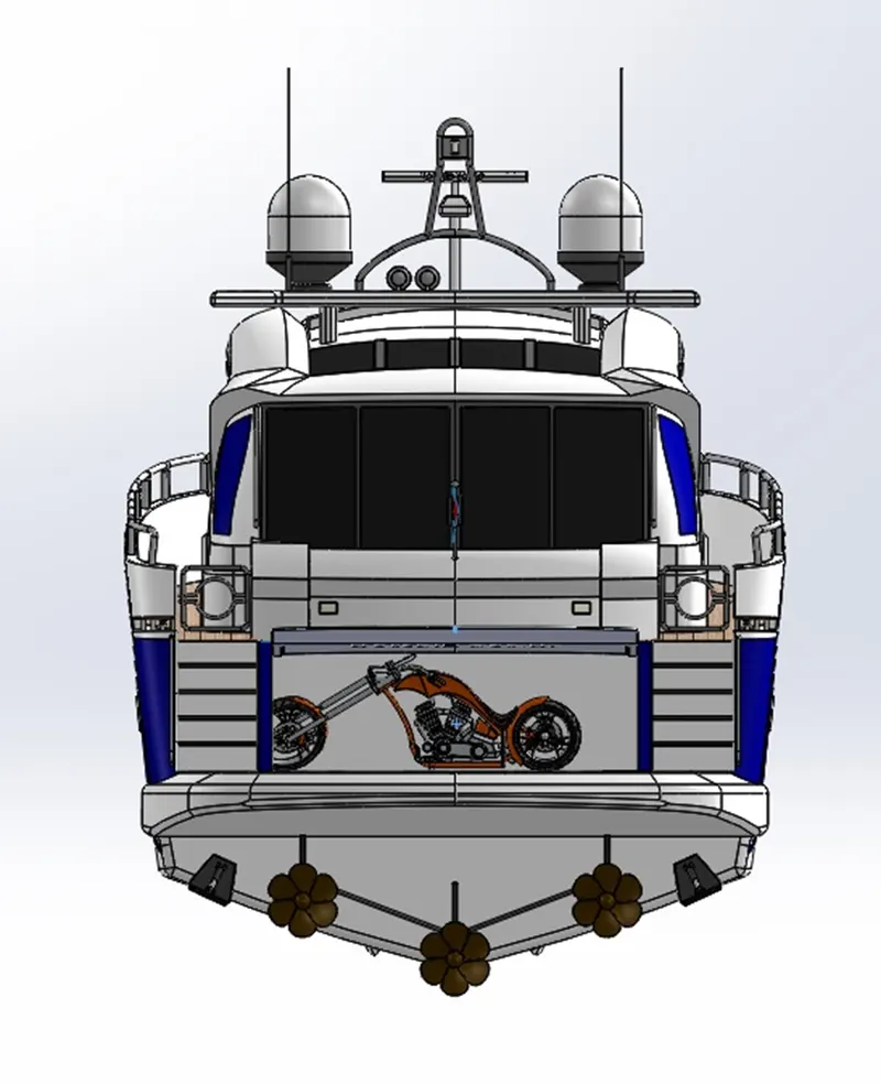
Pic.17
RENDERING
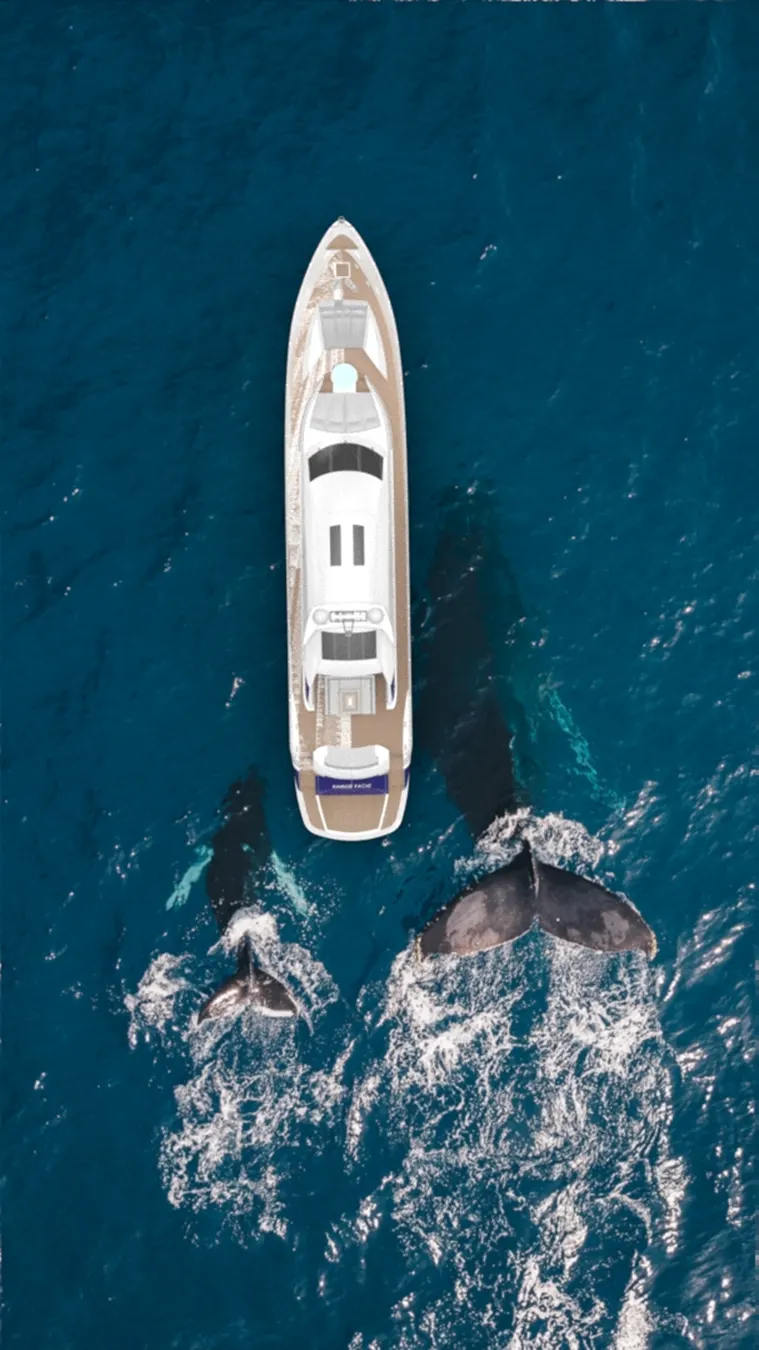
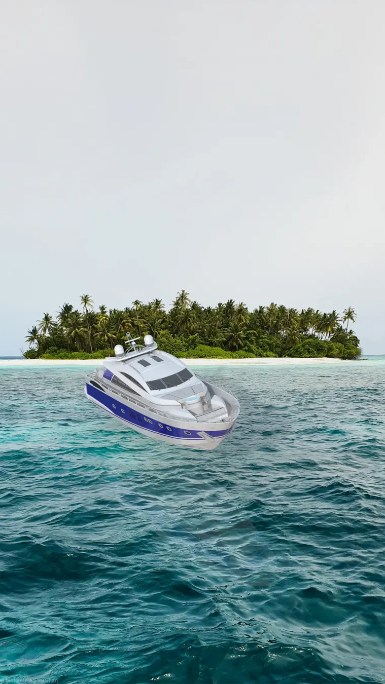
Rendering is process of making real time products for this we use PhotoView 360 and Solidworks Visualize.
PhotoView 360 is a SOLIDWORKS add-in that produces photo-realistic renderings of SOLIDWORKS models. The rendered image incorporates the appearances, lighting, scene, and decals included with the model. PhotoView 360 is available with SOLIDWORKS Professional or SOLIDWORKS Premium.
SOLIDWORKS Visualize provides industry-leading rendering capabilities with visual design-oriented features and workflows in place. This allows for fast and easy creations of visual content that communicates a designer's vision and showcases your part in the most stunning way.
Quickly and easily create professional photo-quality images, animations, and other interactive 3D content to get your products to market faster. SOLIDWORKS Visualize allows us to leverage our 3D CAD data to create photo quality content in the fastest and easiest way we can-from images to animations interactive web content, and immersive Virtual Reality. It brings our products to life SOLIDWORKS Visualize is the camera for our CAD data.
Some renderers are fast but output low-quality images. Some produce great quality but take six months to learn. Others are easy to use, but take four hours to render an image. SOLIDWORKS Visualize provides the right combination of quality, speed, and ease of use, and is the best renderer.
Features Used
1.Environment settings
2.Light settings
3.Colours and material editing
4.Scene Composition
RENDERING IMAGES
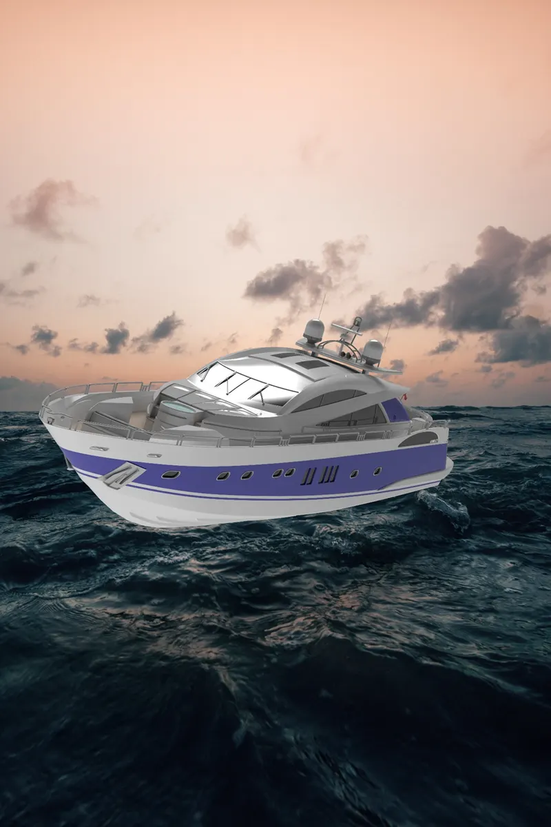
Pic.18
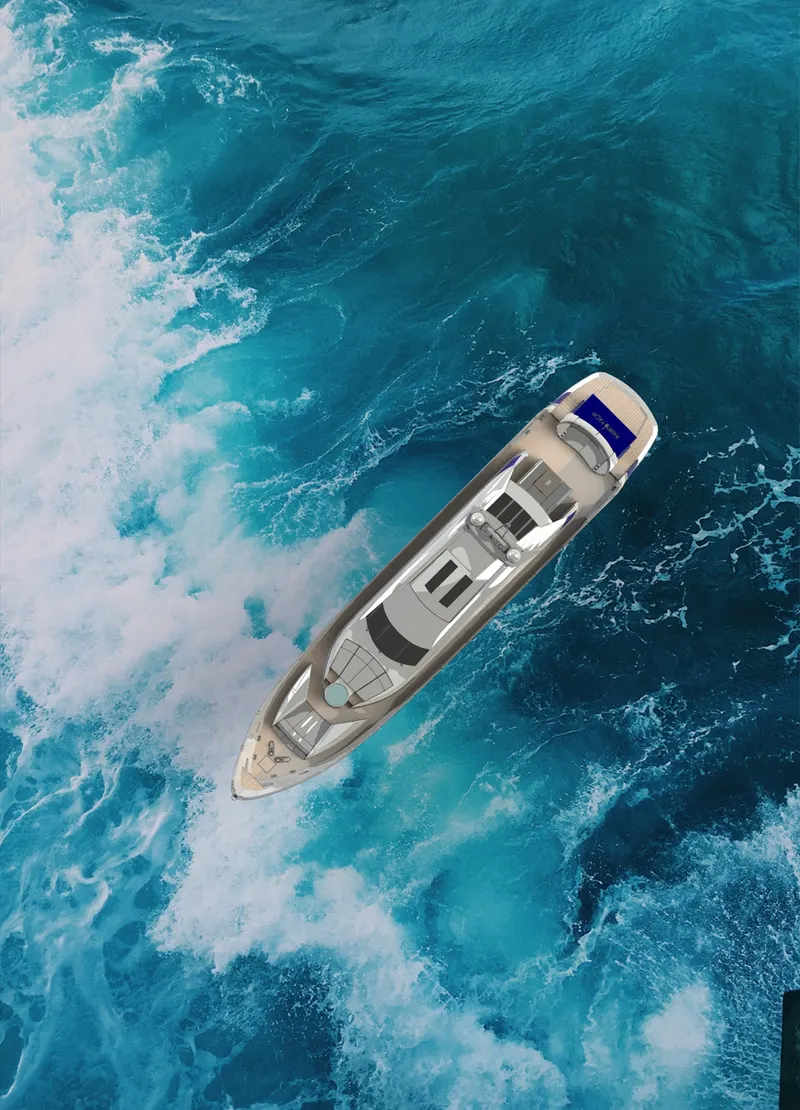
Pic.19
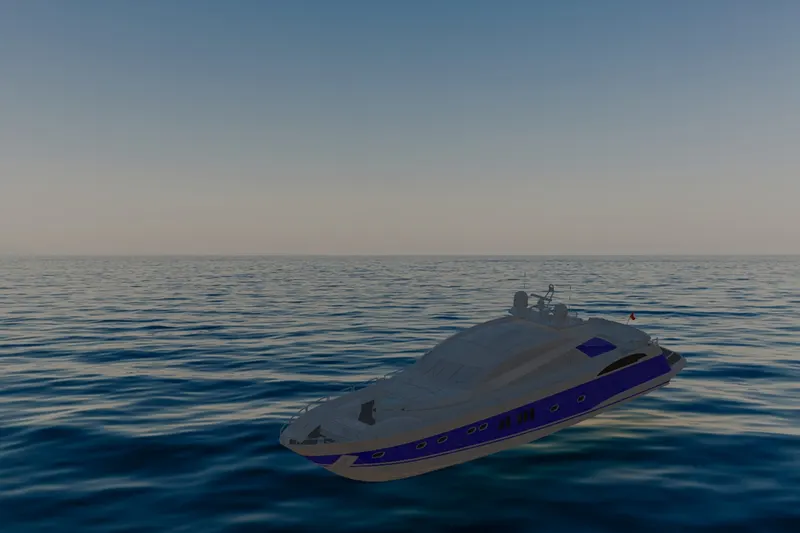
Pic.20
Pic.21
Pic.22
CONCULSION
From this Project I have learned to Design a Sunseeker Predator Yacht using Solidworks 3D modelling software.Many new features,tools and assemblying and Rendering have been also learned.This project helps me to gain good foundation and more knowledge in Solidworks 3D
Pack and Go Zip File link
https://drive.google.com/file/d/1DlAUEOp1wpe7tVgQ1jAtPHG1OwR2p6Ar/view?usp=sharing