Week 8 - Challenge 5 - Door Trim Lower
WEEK 8 CHALLENGE-5
DOOR TRIM LOWER
Aim
To Create the Door Trim Lower component from the given Class A Surface.
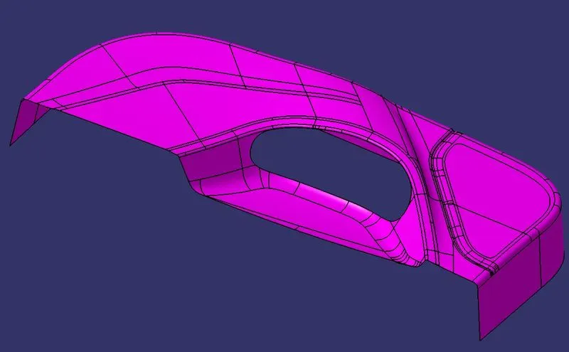
Pic.1 (Given Class A Surface)
Steps to perform given task
- Create Tooling axis.
- Create Class B Surface from Class A Surface.
- Create Class C Surface.
- Create a solid body using close surface command.
- Perform draft analysis for given model.
Create Tooling axis:
Generally,Tooling axis is created using Bisecting line method.But in this challenge we use another method to create the tooling axis,First select the Class A Surface then using Measure inertia command select Create Geometry then a small window will pop up from there select Associative Geometry then Centre of Gravity.Now make a line at point using Point-direction through ZX Plane direction.Now,performed a draft analysis check from that line whether the created tooling axis is in the correct position or not. If, in the draft analysis check the surface highlighted with green colour on both sides of the surface the tooling axis is in the correct position and direction.
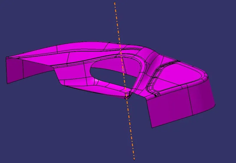
Pic.2 (Tooling Axis)
Create Class B Surface from class A Surface:
Class B surface is created by offset the class A surface inside as per our thickness requirement (thickness is 2.5mm)So,offset the class A to 2.5mm inside. Once the offset is created, we can observe some patches on the offset surface by taking the boundary for the offset surface, those patches are formed due to the fillets on the class A surface.To cover all these Patches, we will use the JOIN command in which uncheck the CHECK CONNEXIVITY and in SUB-ELEMENTS TO REMOVE option we will select the filleted surface to remove and click OK. We will do the same for all PATCHES REGION.After removing the filleted surface, we will disassemble the surface body by using the DISASSEMBLE command. Once the 2 surface domain created we will create the BOUNDARY curve for both surfaces.Then,creating the boundary curves, we will use EXTRAPOLATE command to extend the surfaces till the intersection then we will use the TRIM command to remove the extra surfaces and they will be joined together automatically.Same procedure is followed for all patches.
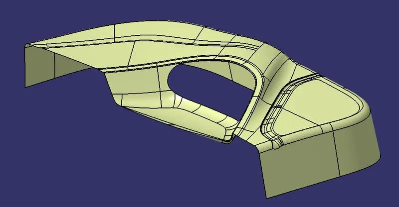
Pic.3 (Class B)
Create Class C Surface:
To create the class C surface concerning the boundary of the class A surface, used the Sweep command. Initially, extracted the boundary of the class A surface with Point continuity, and sweep the extracted boundary concerning the surface at 90deg (for draft angle) for 9 mm to intersect properly with the class B surface.We've to create two Class C Surfaces, one is for the outer surfaces and the other is for the Inner Cutting region.
Once we sweep all the surface boundaries of class A, extrapolate the sweeped surfaces until both surfaces got intersected properly, and trim them to remove extended extrapolated surfaces to get a proper sweep boundary throughout the entire surface, including the centre inner cutting region of the Door trim Lower.
Now, join both class A and sweep boundary to get the complete class C surface.
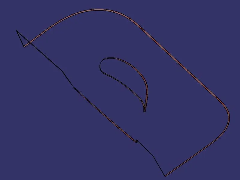
Pic.4 (Class C)
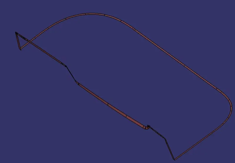
Pic.5 (Class C Outer surface)
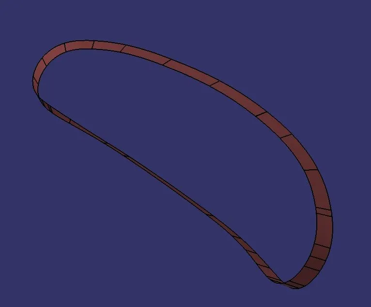
Pic.6 (Class C Inner Cutting Surface)
Now, unhide the class B and class C surfaces. Check whether all the sides of class B and Class C surfaces are intersecting properly with each other, to get a closed surface by trimming class B and class C surfaces. If the class B and class C sides are not intersected properly, we need to extrapolate the sides of the class B surface which are not intersecting with the class C surface. Now, check class B and class C surface boundaries whether all the sides are intersecting or not with each other. Once the surfaces are intersecting properly trim them together to get a closed surface.
Create a Solid body using close surface command:
Creating a solid body from the final result that we get after trimming the Class C Surface using the closed surface command which makes a solid surface between the closed surface.
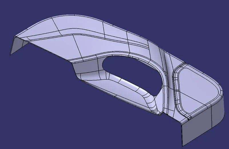
Pic.7
Perform draft analysis:
Draft Analysis
After the conversion of the Closed surface into a Solid Part, it is subjected to Draft analysis to check if the Part can be manufactured using the Molding process and meets all the Injection molding requirements.
For molded or cast parts, the draft angle is the amount of taper perpendicular to the parting line. It is measurable in degrees. Because plastic shrinks and sticks on molding surfaces as it cools, we draft the walls of the plastic part so that it ejects or breaks free from the molding surfaces more easily and without dragging. To reduce the risk of damage to the parts and ensure ejection, a functional injection molding part must have drafts on both the cavity and core sides.It is performed using tooling axis as tooling direction and Minimum draft angle considered is 3 degree.When the value obtained is less than 3 it will be highlighted in red, These regions drafting is impossible .Hence Tooling axis should be changed or additional process is to done to produce the part.
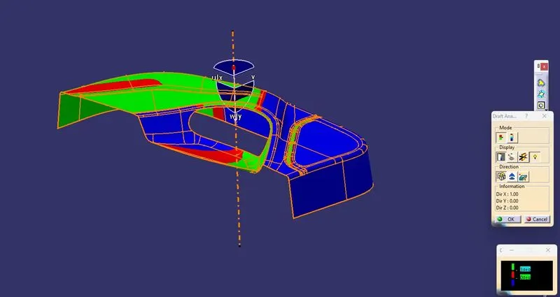
Pic.8 (Draft Analysis For Class A Surface)
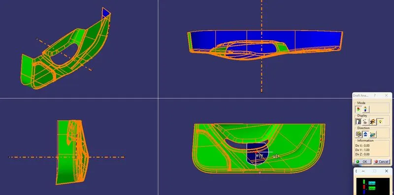
Pic.9 ( Draft Analysis for Closed Surface)
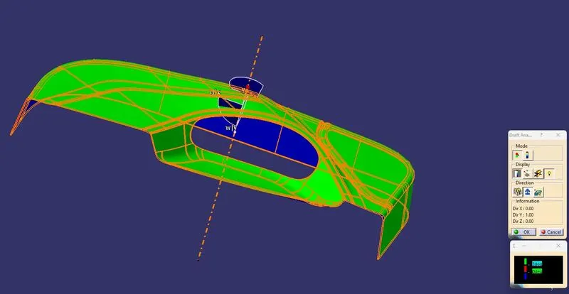
Pic.10 (Draft Analysis for Closed Surface)
Tree Structure:
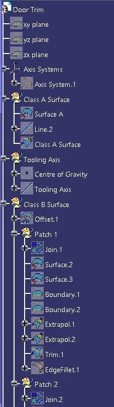
Pic.11
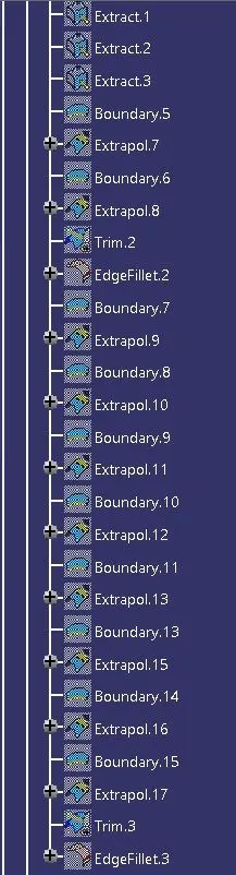
Pic.12
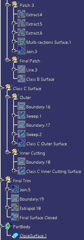
Pic.13
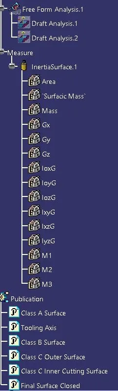
Pic.14
Publication:
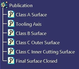
Pic.15
Different Views:
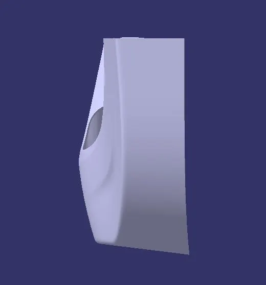
Pic.16 (Front View)
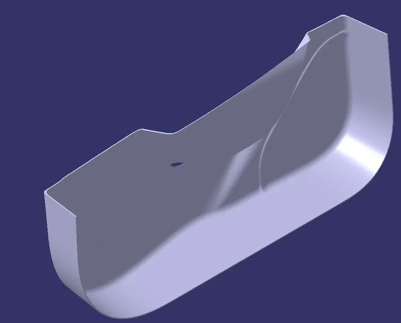
Pic.17 (Isometric View)
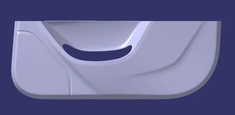
Pic.18 (Side View)
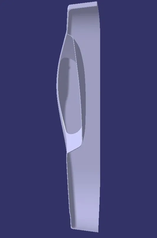
Pic.19 (Top View)