Hood design-Week 2
HOOD DESIGN OF A CAR
AIM
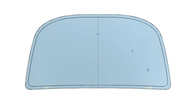
To design the hood of a car with the given input Outer panel and its dimensions.
HOOD INTRODUCTION
The hood (North American English) or bonnet (Commonwealth English) is the hinged cover over the engine of motor vehicles. Hoods can open to allow access to the engine compartment or trunk (boot in Commonwealth English) on rear-engine and some mid-engine vehicles) for maintenance and repair.
A car hood also referred to as a bonnet in some other countries is the hinged cover that rests over the engine of a front-engine vehicle. Its purpose is to provide access to the engine for repair and maintenance. Car hoods are typically constructed from steel and sometimes from aluminum.

Pic.1
In UK terminology, a hood refers to a fabric covering over the passenger compartment of the car (known as the “roof” or “top” in the US). For many motor vehicles built in the 1930s and 1940s, the resemblance to an actual hood is clear when it is opened and viewed from the front; in modern vehicles, it still serves the same purpose, but no longer resembles hea covering. On front-engined cars, the hood may be hinged at either the front or the rear edge, or in earlier models (e.g. the Ford Model T) it may be split into two sections, one on each side, each hinged along the centerline.
A further variant combines the bonnet and wheel arches into one section and allows the entire front bodywork to tilt forwards around a pivot near the front of the vehicle.
Hoods are usually made from the same material as the rest of the body. This can be steel, aluminum, fiberglass, or carbon fiber. However, some aftermarket companies produce The hood release system is common on most vehicles and typically consists of an inner hood latch/lock handle, a hood release cable, and a hood lock assembly. The hood lock handle is usually located under the steering wheel, next to the driver’s seat, or in the door frame

Pic.2
HOOD DESIGN
There lot more things before the hood gets in to designing hands that to be considered.
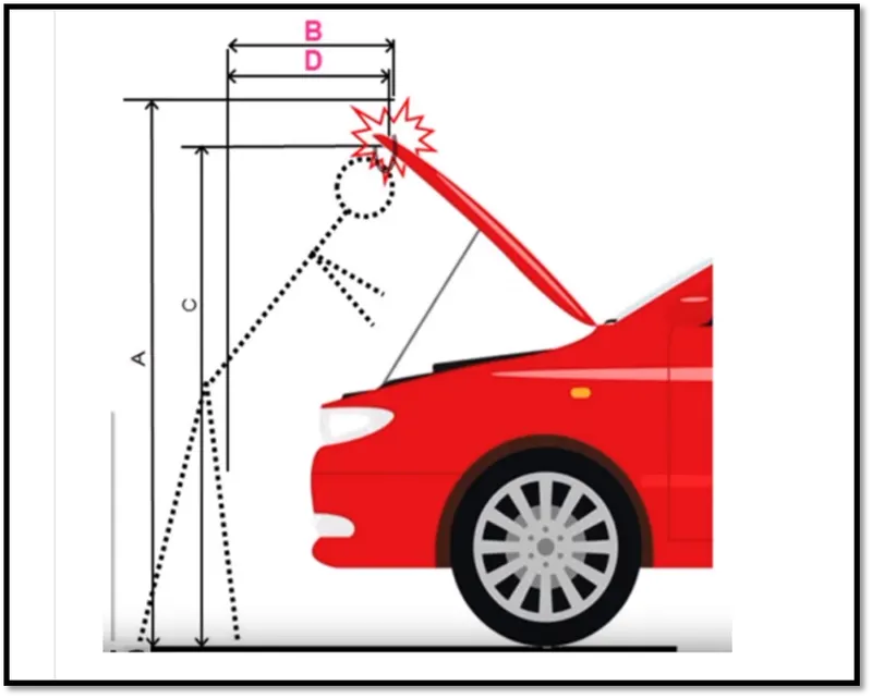
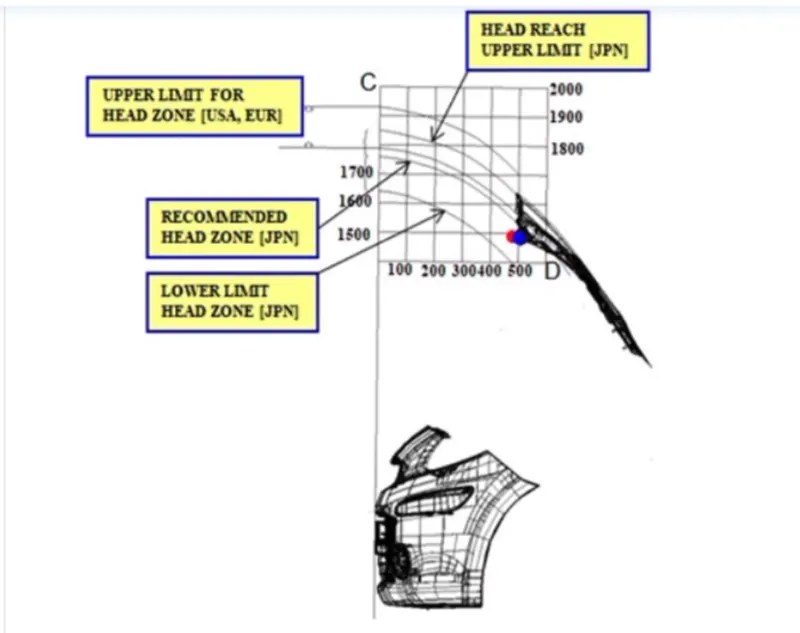
The height of the hood is designed based on the country standards as the height of a average person changes from place to place.
The material consideration is also required that should be cost effective to manufacture.
The Hood should be designed with a light weight for the pedestrain safety as the person hit to hood there should be minimal harm to the person.
Pic.3
Pic.4
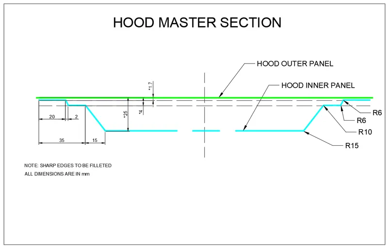
Input design for the input panel is shown below
Pic.5
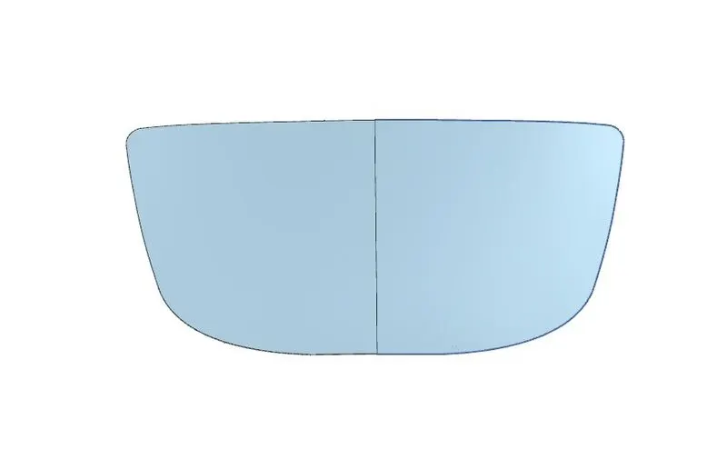
Hood Outerpanel
Pic.6
Pic.7
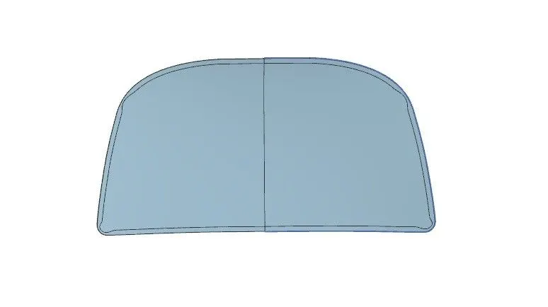
So inorder to get the final input design the outer model should be modified .First the outer panel should be exactly halved into middle using mid plane and should work on the half part.Then all the features should be mirrored and sewed together.
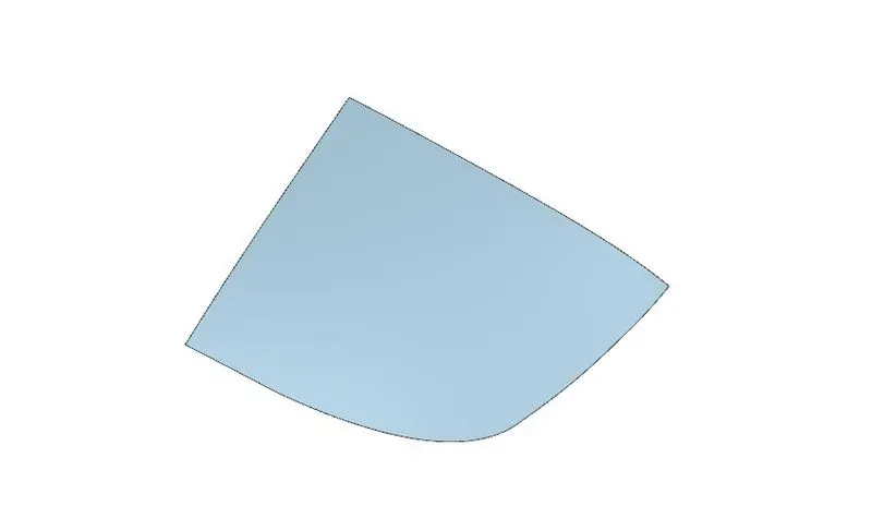
Pic.8
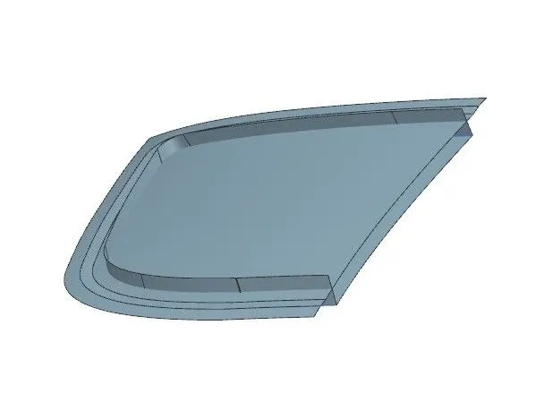
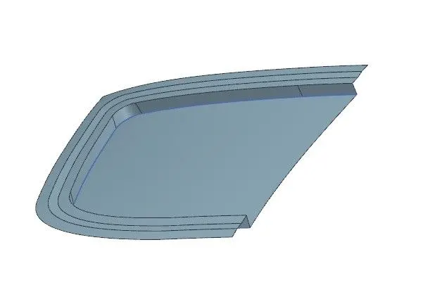
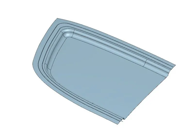
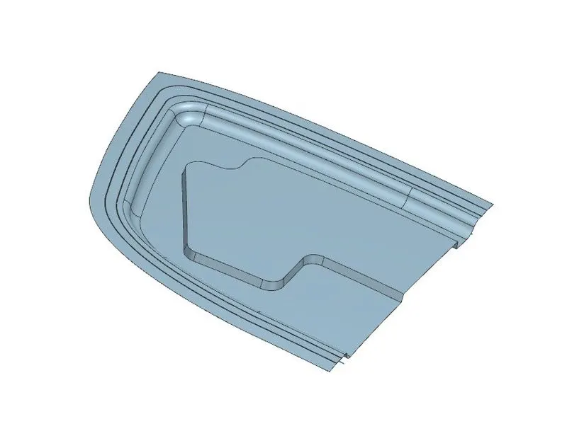
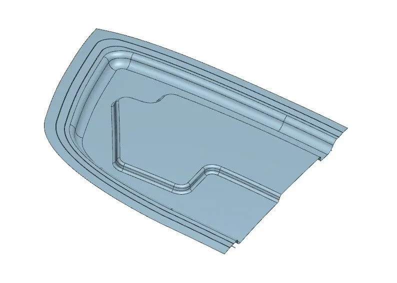
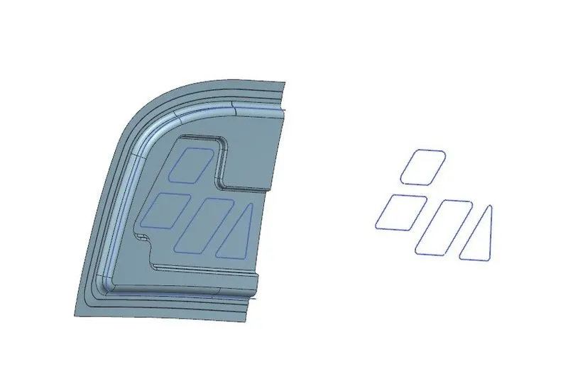
Now the features are to be given like Law extension,Trim and Extend, Mastic points, Embosses for hinges and latch reinforcement etc.
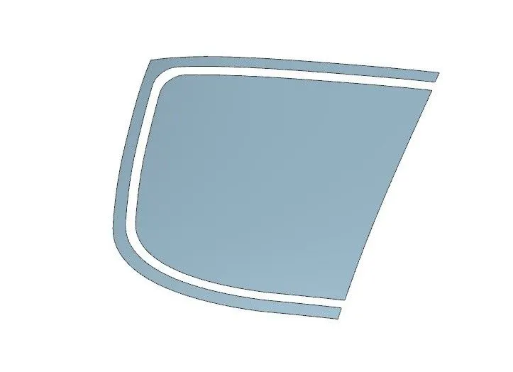
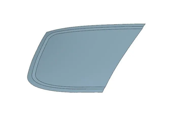
Through curves command is used to join between the both upper face and the lower offse faces.remaining steps are shown below.
Pic.9
Pic.10
Pic.11
Pic.12
Pic.13
Pic.14
Pic.15
Pic.16
Pic.17
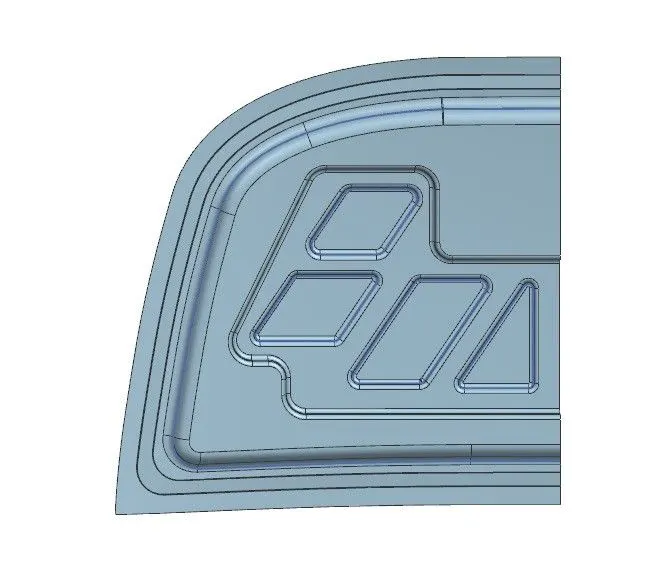
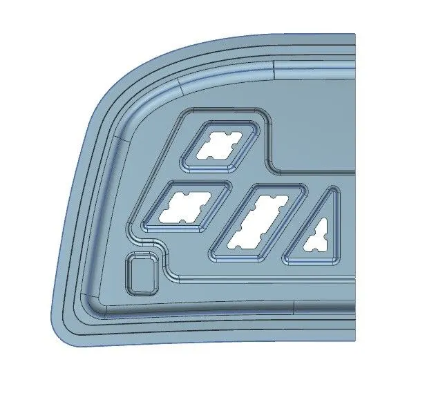
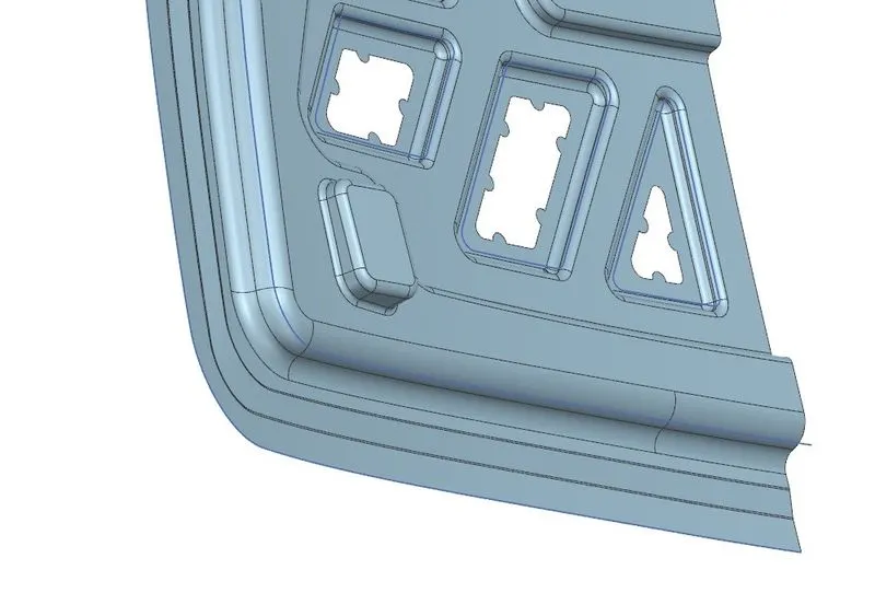
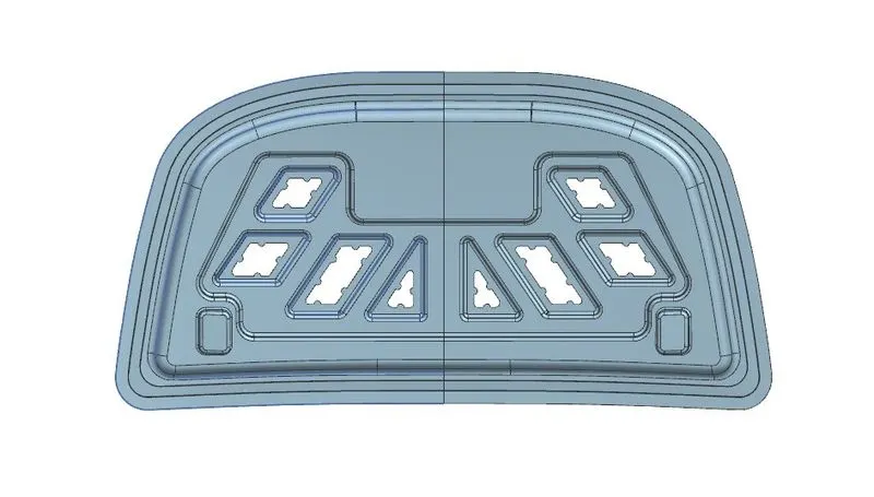
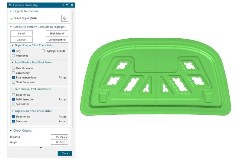
Now, below image is shown for Mastic embosses and the Hinge embosses.To stick the inner panel with the outer panel mastic points were created and the maximum distance between them should be 5mm.So after completing the mastic points the inner panel should be mirrored and sewed together. Then the sewed feature should be examined with geometry to check any cracks were built in between.
Pic.18
Pic.19
Pic.20
Pic.21
Here geometry check is performed by using Examine geometry command and if a green colour is shown so that no errors were present and if it is shown in red marks then it indicates there are some errors in joining the mirrored part or intersecting part. Now the Hinges should be attached at the ends of the embossed inner panel edges.
HINGE PLACEMENT
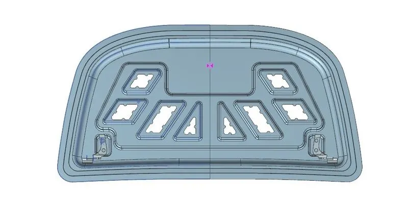
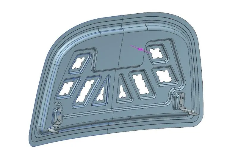
First hinges are placed on to the embosses and as inner panel is applied with fixed constraint hinge is placed parallel and touch constraint.
Then the hinge is mirrored with associative connection to other side to get the same hinge position on other side of the inner panel.
Pic.22
Pic.23
STRIKER ATTACHMENT
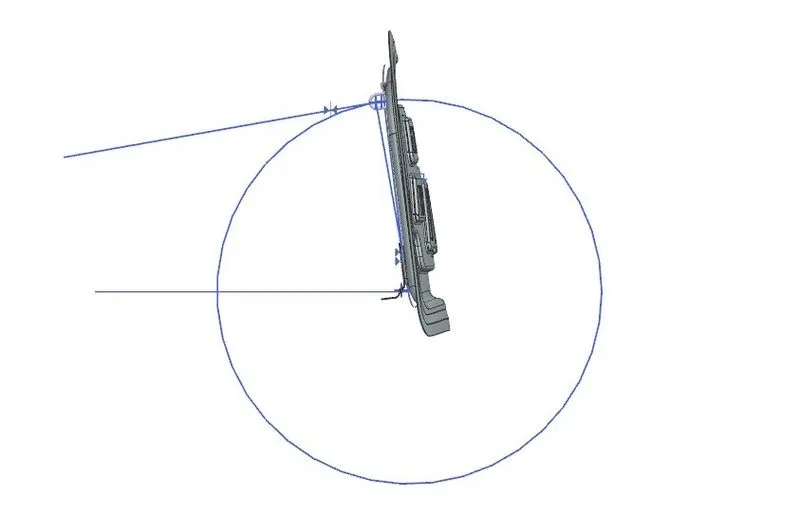
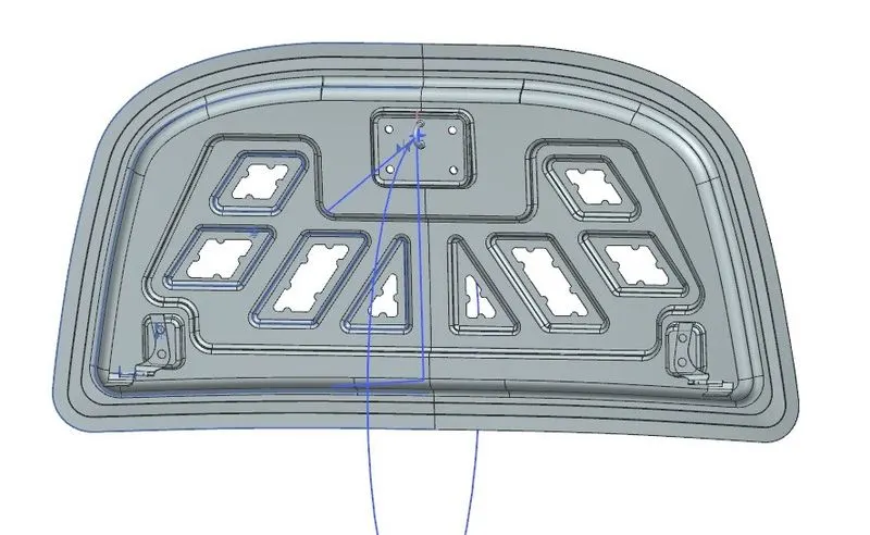
The latch/Striker position is from the basis of hinges centre point. Two points is marked from the two hinge axis and a line is drawn from the two points. A midpoint is taken from the line for positioning the latch
Now a circle is drawn as that point as a centre with a radius of approximately 640 mm and a horizontal line draw from the centre point of axin drawn between two hinges to define the angle. The tangent line is drawn on that circle. Then latch is coincided with that tangent line.
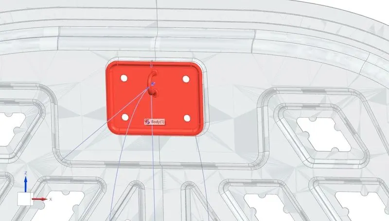
So after latch position is fixed then the emboss is created from the latch surface using wave geometry linker in to the inner panel file. Striker emboss is shown in the below image.
Pic.24
Pic.25
Pic.26
HOOD OUTER PANEL
Hemming Operation:
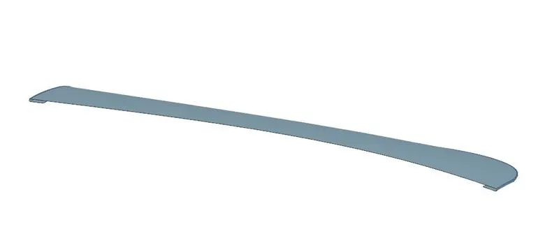
Hemming is a forming operation in which the edges of the sheet are folded or folded over another part in order to achieve a tight fit. Normally hemming operations are used to connect parts together, to improve the appearance of a part and to reinforce part edges. In car part production, hemming is used in assembly as a secondary operation after deep drawing, trimming and flanging operations to join two sheet metal parts (outer and inner) together. Typical parts for this type of assembly are hoods, doors, trunk lids and fenders. The accuracy of the hemming operation is very important since it affects the appearance of the surface and surface quality. Material deformations, which occur during the hemming process, can lead to dimensional variations and other defects in parts. Typical hemming defects are splits or wrinkles in the flange, material overlaps in the corner areas or materia roll-in. This is why it is important to use simulation tools in order to, on the one hand, better understand the hemming process and, on the other hand, significantly reduce the number of “trial and error” loops during tryout und production.
There are various types of hemming operations and they are :-
1.Conventional die hemming :
Conventional die hemming is suitable for mass production. In die hemming, the flange is folded over the entire length with a hemming tool. Normally the actual hemming is a result of a forming operation in which the flange is formed with a hemming tool after the drawing and trimming operations have been completed. The formed flange is then hemmed in several process steps. These steps include, for example, the pre-hemming and final hemming depending on the respective opening angle of the flange. Production plants for conventional die hemming are very expensive, but the cycle times are very low.
2.Roll hemming :
Roll hemming is carried out incrementally with a hemming roller. An industrial robot guides the hemming roller and forms the flange. Roll hemming operation can also be divided into several pre-hemming and final hemming process steps. Roll hemming is very flexible to use and tool costs are significantly lower as compared to those of conventional die hemming. However, the cycle times are much higher since the hemming is realized using a hemming roller which follows a defined path. A corner reliefs are provided at the edges of hemmed part to provide corner reliefs.
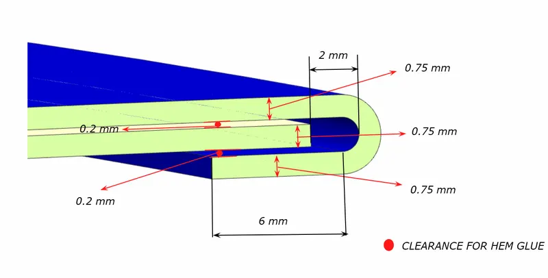
Pic.27
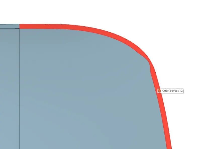
Pic.28
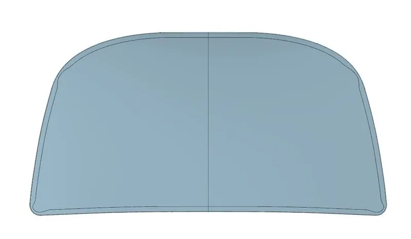
Pic.29
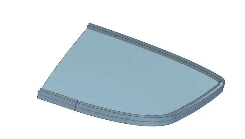
Pic.30
Pic.31
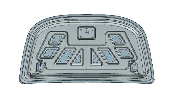
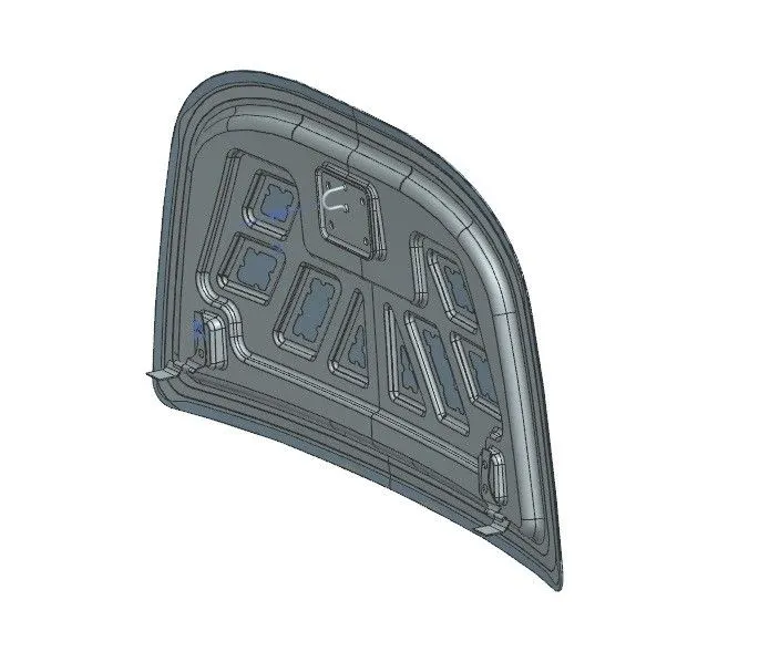
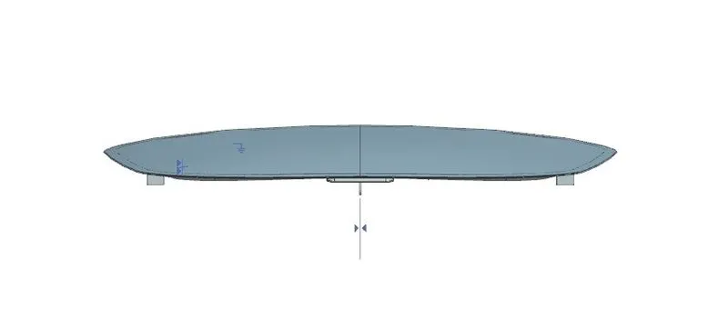
FINAL ASSEMBLY
Pic.32
Pic.33
Pic.34
Pic.35
CONCLUSION
From this challenge I have learned to design Car Hood using Siemens NX CAD .I have been also learned more knowledge and features in it. Therefore the Design of Hood considering various rules and approaches has been done and validated successfully.