Wiring harness design in CATIA V5 - 3D modeling Week 2 Challenge
WEEK 2 CHALLENGE
Aim:
To define Connectors & Clip as Electrical Connector using Electrical Part design Workbench. Define all the necessary properties to Connectors & Clip which are given.
Steps:
- Create/Download Connector 3D - The 3D model of the connector is downloaded from websites or created manually.
- Create required Geometrical Parameters - The required geometrical parameters like Connector Point, Bundle Entry Point, Cavity Point, Connector Axis, Cavity Axis, etc are created.
- Define Part as Connector - We need to define the part as a Connector.
- Define Connector Connection Points - The point where the connector is connected with this connector is called as Connector Connection Point. We need to define the Connector Connection Point.
- Define Bundle Connection Points - The point where the bundle is connected to the connector is called Bundle Connection Point. We need to define the Bundle Connection Point
- Define Cavity Connection Points (if any) - The point where the cavity is connected to the connector is called as Cavity Connector Point. We need to define the Cavity Connection Point.
Components:
1. Deutsch DT06 – 08SA
i. Download Connector 3D:
The 3D model is downloaded from the given link and save as a CATpart file.
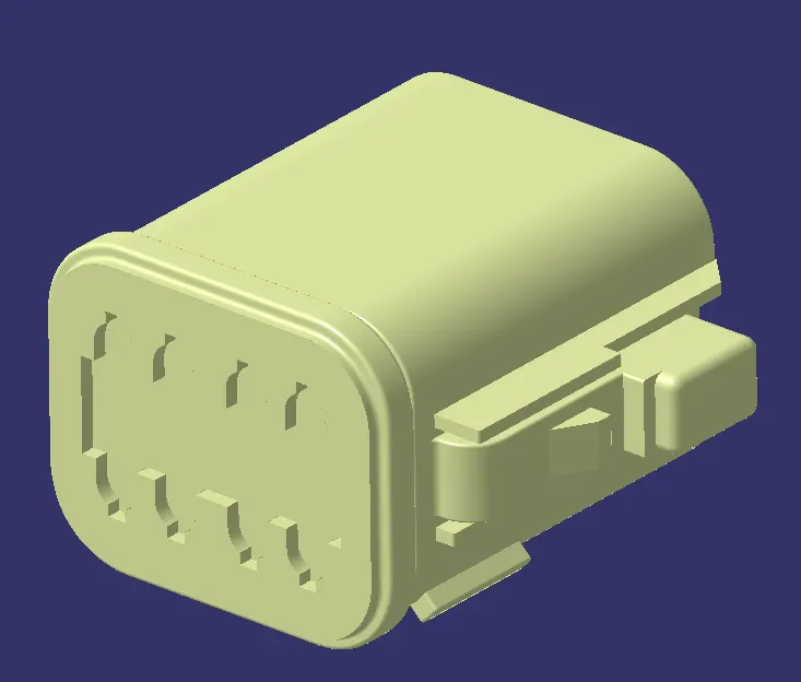
Pic.1
ii. Geometrical Parameters:
Connector Point: The connector Point is created at the mating side of the connector.
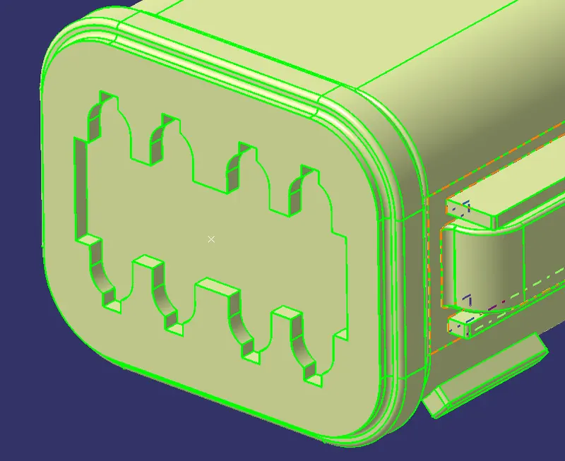
Pic.2
Connector Axis: The connector axis is created with respect to Connector Point.
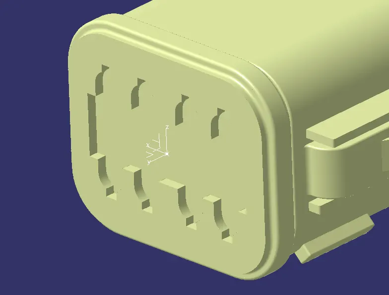
Pic.3
Bundle Entry Point: The bundle entry Point is created at the rear part of the connector.
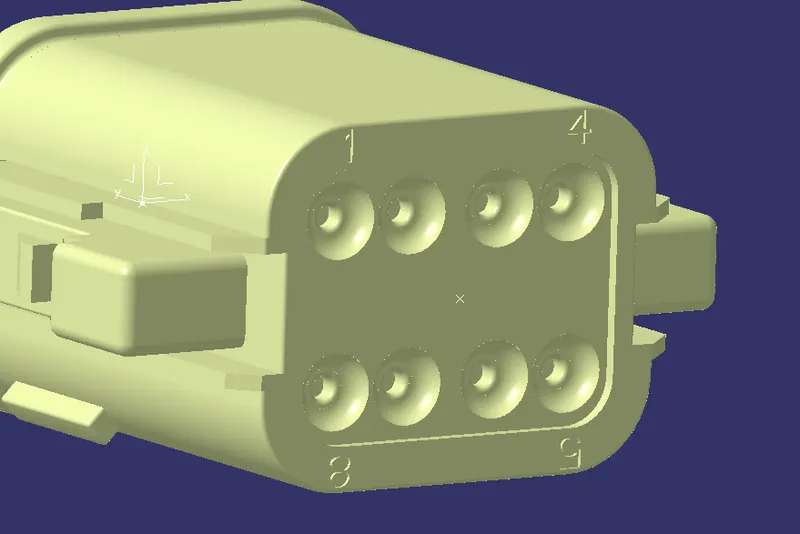
Pic.4
iii. Definition of Component:
The component is defined as the connector using "Define Connector" tab in the "Electrical Part Workbench". The number of terminals is defined.
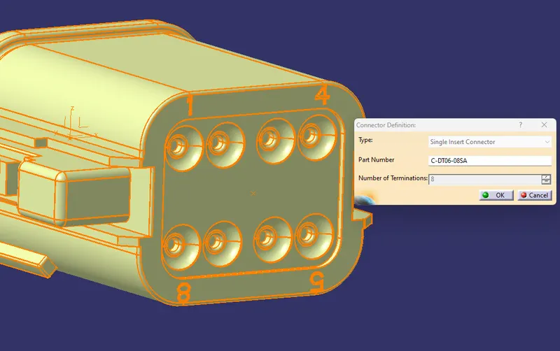
Pic.5
iv. Connector Connection Point:
The connector connection point is defined using "Connector Connection Point Definition" tab in the "Electrical Part Workbench". The parameters are defined appropriately.
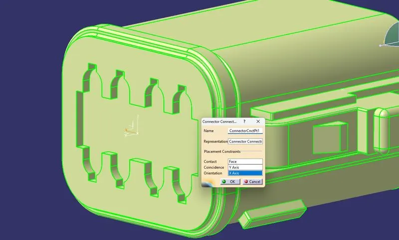
Pic.6
v. Bundle Connection Point Definition:
The bundle connection point is defined using "Bundle Connection Point Definition" tab in the "Electrical Part Workbench". The parameters are defined appropriately.
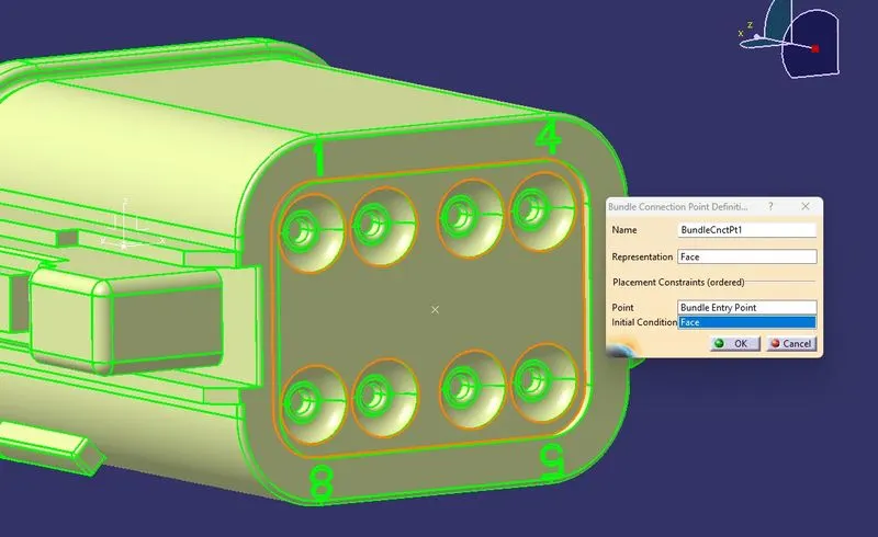
Pic.7
2. Tyco 174357-2:
i. Download Connector 3D:
The 3D model is downloaded from the given link and save as a CATpart file.
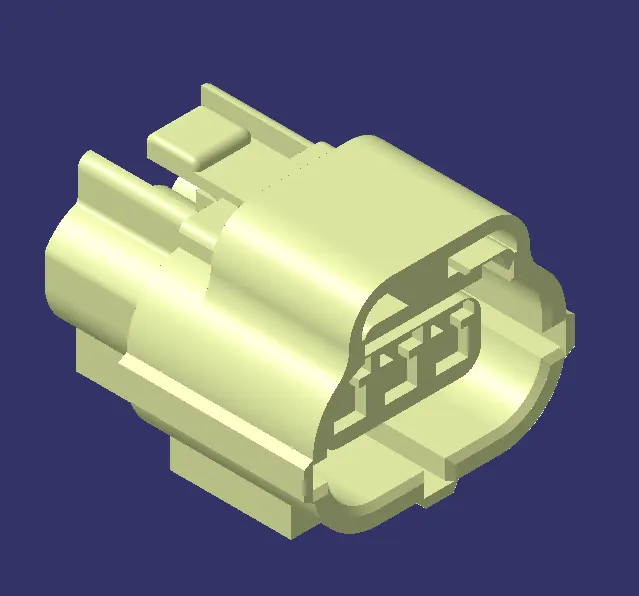
Pic.8
ii. Geometrical Parameters:
Connector Point: The connector Point is created at the mating side of the connector.
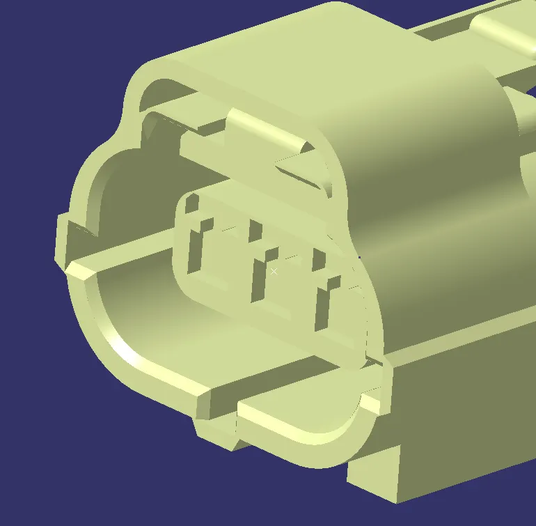
Pic.9
Connector Axis: The connector axis is created with respect to Connector Point.
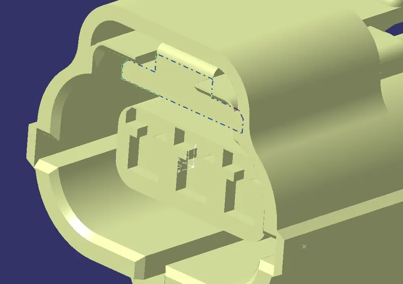
Pic.10
Bundle Entry Point: The bundle entry Point is created at the rear part of the connector.
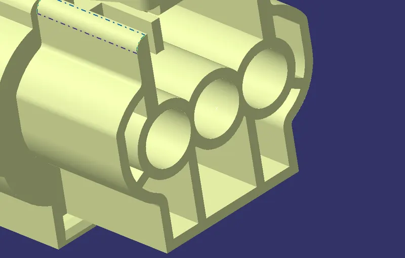
Pic.11
Cavity Point: The Cavity Point is created at the cavity position of the connector.
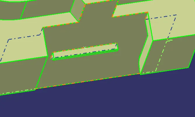
Pic.12
Cavity Axis: The Cavity axis is created with respect to Cavity Point.
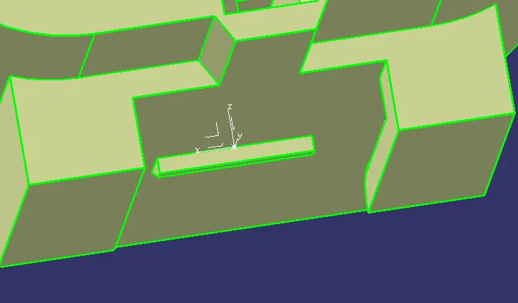
Pic.13
iii. Definition of Component:
The component is defined as the connector using "Define Connector" tab in the "Electrical Part Workbench". The number of terminals is defined.
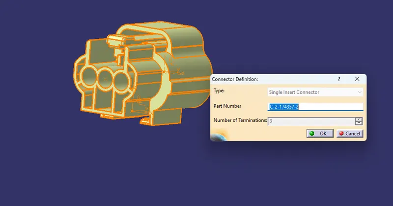
Pic.14
iv. Connector Connection Point:
The connector connection point is defined using "Connector Connection Point Definition" tab in the "Electrical Part Workbench". The parameters are defined appropriately.
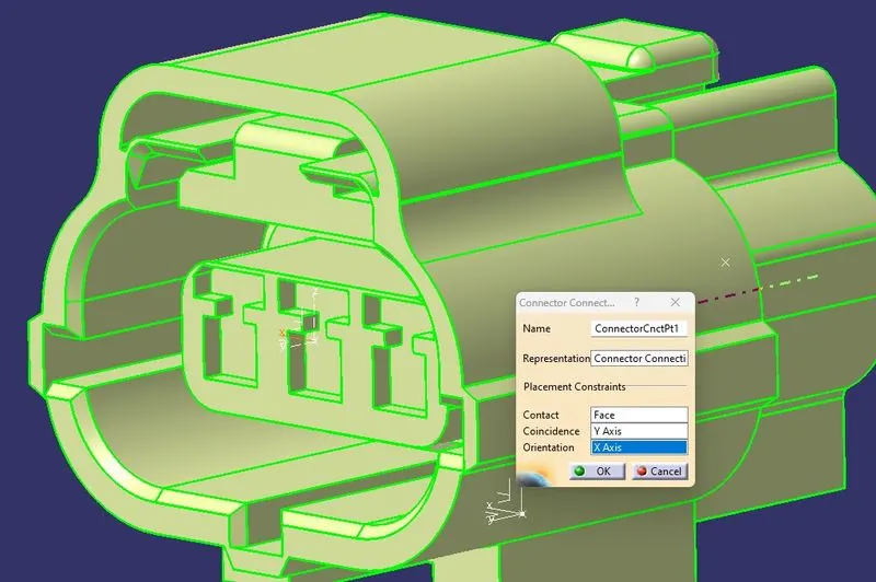
Pic.15
v. Bundle Connection Point Definition:
The bundle connection point is defined using "Bundle Connection Point Definition" tab in the "Electrical Part Workbench". The parameters are defined appropriately.
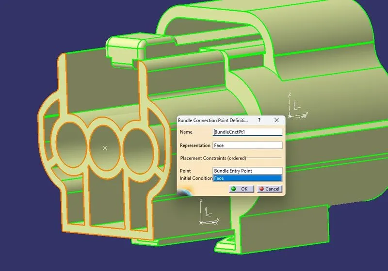
Pic.16
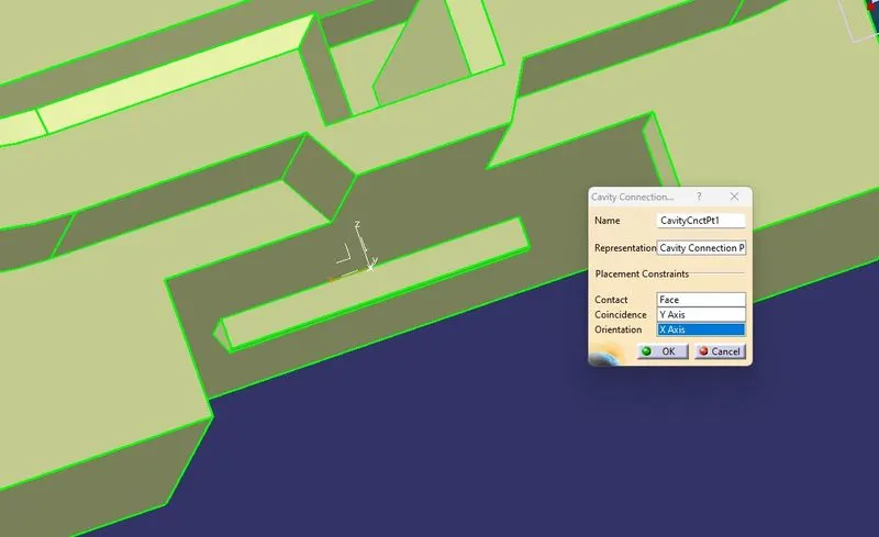
vi. Cavity Connection Point:
The cavity connection point is defined using "Cavity Connection Point Definition" tab in the "Electrical Part Workbench". The parameters are defined appropriately.
Pic.17
3. Tyco 85229-1
i. Download Connector 3D:
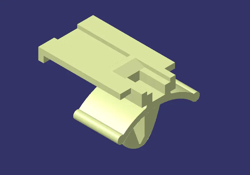
The 3D model is downloaded from the given link and save as a CATpart file.
Pic.18
ii. Geometrical Parameters:
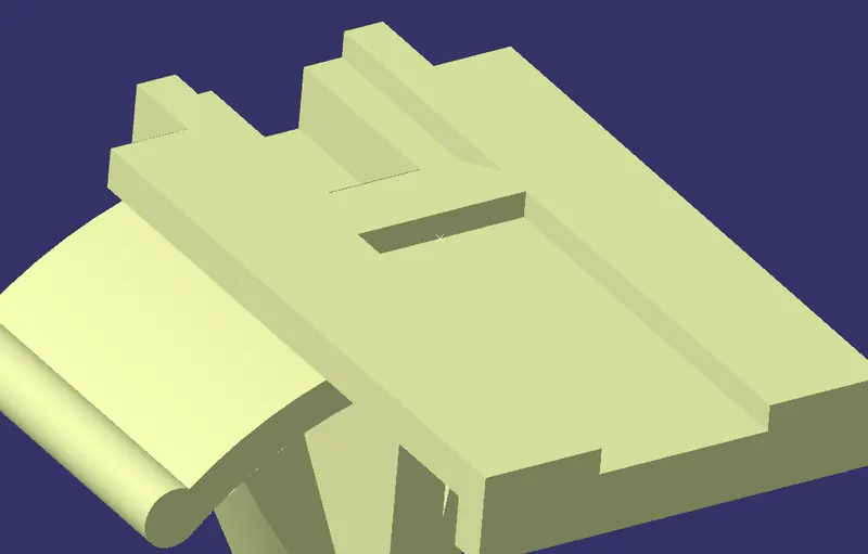
Cavity Point: The Cavity Point is created at the cavity position of the connector.
Pic.19
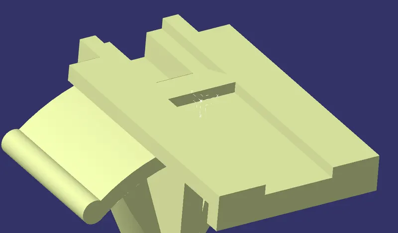
Cavity Axis: The Cavity axis is created with respect to Cavity Point.
Pic.20
iii. Definition of Equipment:
The component is defined as equipment using "Define Equipment" tab in the "Electrical Part Workbench".
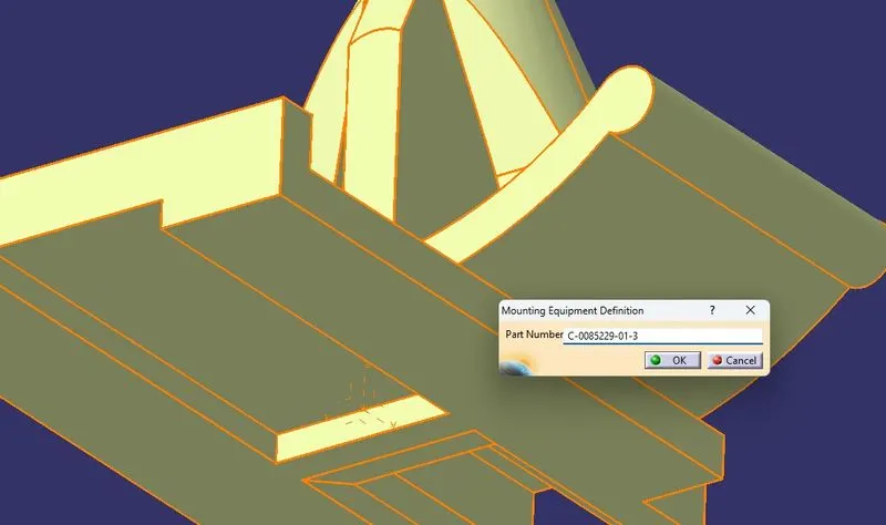
Pic.21
iv. Definition of Cavity & Cavity Connection Point:
The defined equipment is further defined as Cavity using "Define Cavity" tab in the "Electrical Part Workbench".
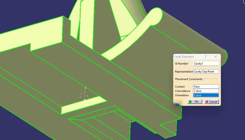
Pic.22