Week 9 - Project - A pillar Design with Master Section
WEEK 9 CHALLENGE - 4
PROJECT-2
A-PILLAR DESIGN WITH MASTERSECTION:
Aim
To create a Solid Body and B Side Features from the the Class A component using Mastersection.
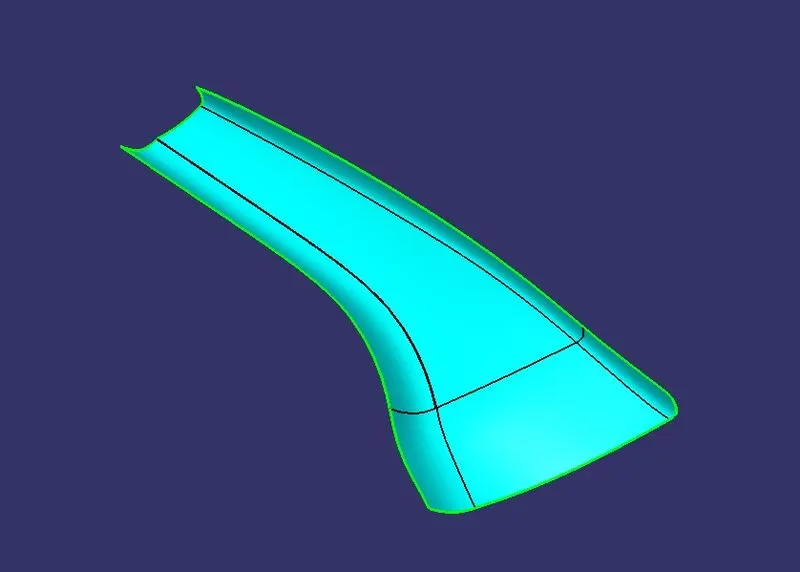
Pic.1 (Given Class A Surface)
Steps to perform given task
- Create Tooling axis.
- Create Class B Surface from Class A Surface.
- Create Class C Surface.
- Create a solid body using close surface command.
- Create Dog House with Supporting Ribs & Upper Cutting
- Perform draft analysis for given model.
Create Tooling axis:
For this challenge ,We can use either Bisecting Method or Normal Method.Bisecting Method is used for Main Tooling Axis,So for that we have to Extract the Lines from mastersection in order to create the Midpoint Point.From the Point using bisecting Line .Created the Tooling Axis.We can Also Try the same method on other two lines.So we get another Dummy axis.Take anyone as Main Tooling Axis.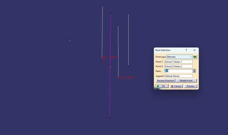
Pic.2 (Tooling Axis)
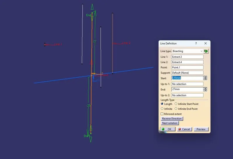
Pic.3
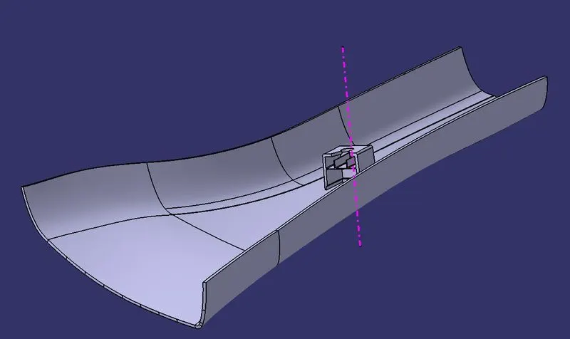
Pic.4 (Main tooling Axis)
Draft analysis for class A surface:
To perform the draft analysis in class A,selected the featured draft analysis tool in the Generative shape design workbench.Before drafting we have to make sure that in the view mode it is selected for the materials.
After selecting the feature draft analysis tool we drag the compass from its position to
the tool axis. Then lock the compass. After that select anywhere on the component and
it will give you the result.
We change the minimum draft for the component to 3°.
We can use the running point option to check the angle of the component.Y direction
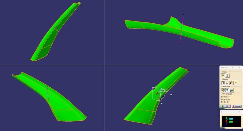
Pic.5 ( Draft Analysis for Class A)
Create Class B Surface from class A Surface:
To create the class B surface for the A Pillar , I offset the class A surface to 2.5mm inside. Once the class A surface is offset created, according to the thickness, we can observe one patch on the offset surface due to the fillets on the class A surface. Now, we need to close those patches. I used Sweep Command to close the patches.
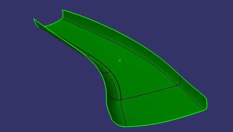
Pic.6 (Class B)
Create Class C Surface:
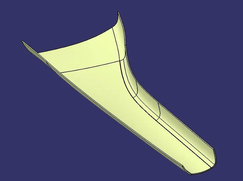
To create the class C surface concerning the boundary of the class A surface, used the Sweep command.Initially,I extracted the edges of the class A surface with tangent continuity by using the multiple extract command. After extracting the class A surface edges correctly, I sweeped the extracted edges with 93deg toward the class B surface. After sweeping the extracted class A surface edges, I extrapolated the edges of the sweep for 2mm to intersect the sweep edges with each other. Now I trimmed the extrapolated surfaces together to create a complete sweep surface towards the class B surface. I joined both the trimmed sweep surface and class A surface together, to get the class A+C surfaces as a single surface. Now, to create a solid body for the door handle we need a closed surface. I trim the class B surface with joined class A+C surface to make the closed surface.
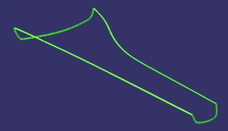
Pic.7 (Class C Surface)
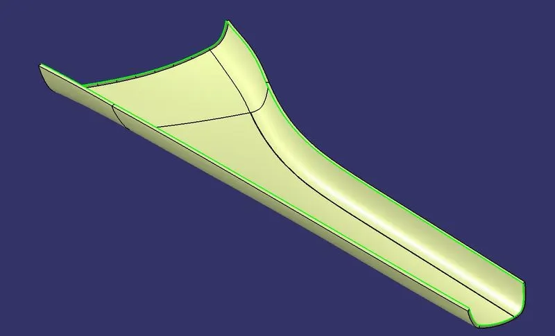
Pic.8 (Class A+C)
Final Trim:
Pic.9
Creating Solid body:
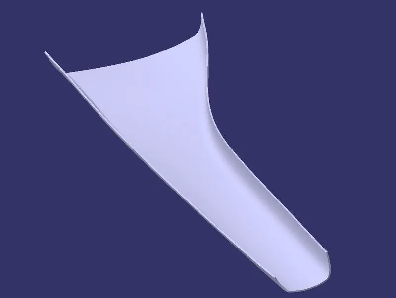
To create the solid body I used the closed surface command in the part workbench. Click on the closed surface command in the part workbench and give the closed surface as an input to create the solid part body.
Pic.10
Create Dog House From Mastersection:
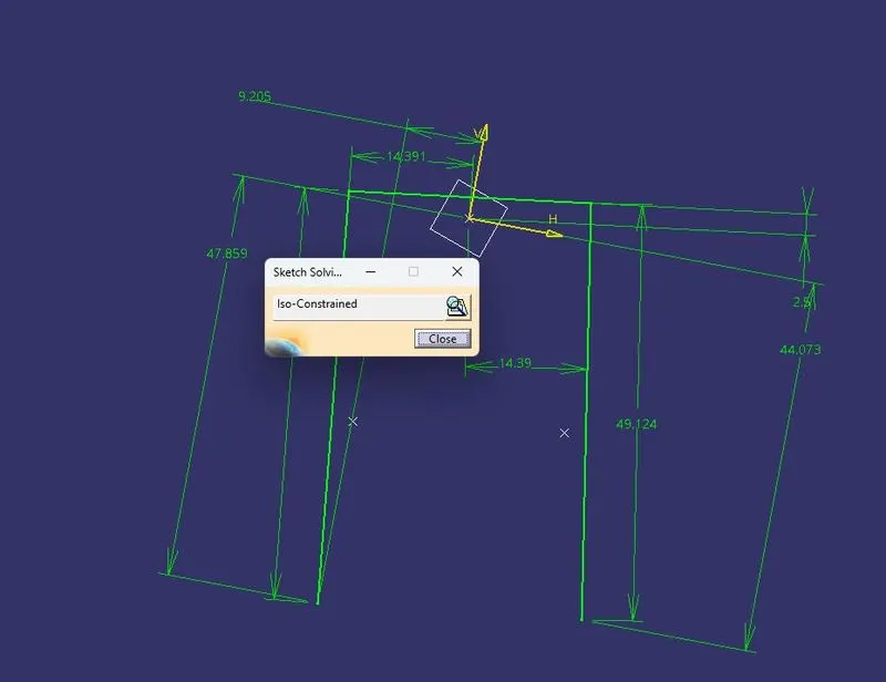
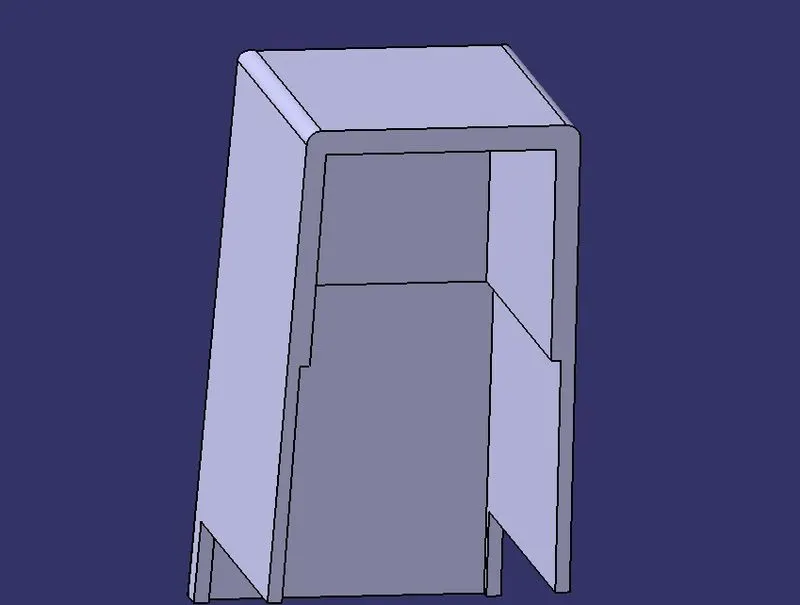
To Create Dog House,We have to create a plane using through 3 point for that take 3 ponts from mastersection and isolate them.After that create a plane.Then Make a sketch and project line from the mastersection and isolate them too.Join the the line without fillets.Then extrude it on plane direction on both side.then,make a part body and go to Part design and Use Thick surface command of 2.5mm inward.
Now create another palne using same through 3 point way and create another sketch for the dog house backside trimming.then extrude the the line plane direction then trim it.Do it for the other side too.
For the bootom cutting.Offset the inner dog house of 1mm outward and upper outer face of about 24.5mm downwards too.then trim it and split it.
Pic.11 (Iso-constrained )
Pic.12
Side Core Axis:
To Create Side Core Axis use the Normal to surface type in Line command and used same plane and point from dog House.
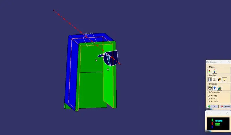
Pic.13
Create Supporting Ribs:
To Create Supporting Ribs,I have extracted all the lines for Ribs then extended it.Using Extrude Command in side core Axis then extracting different side and offset it to close the ribs.After getting a closed surface goto part design and create a Closed surface.
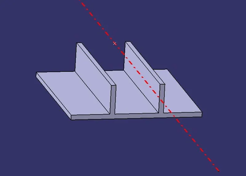
Pic.14
Create Upper Cutting:
For this create another plane on the upper outer surface of dog house.make a sketch with reference to given picture.Draw a circle of about 5mm radius and rest as shown in reference .
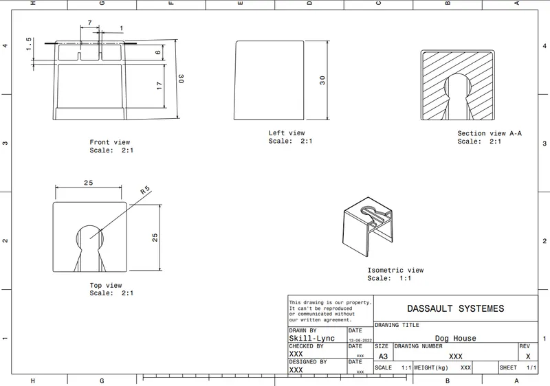
Pic.15 (Given Picture for Reference)
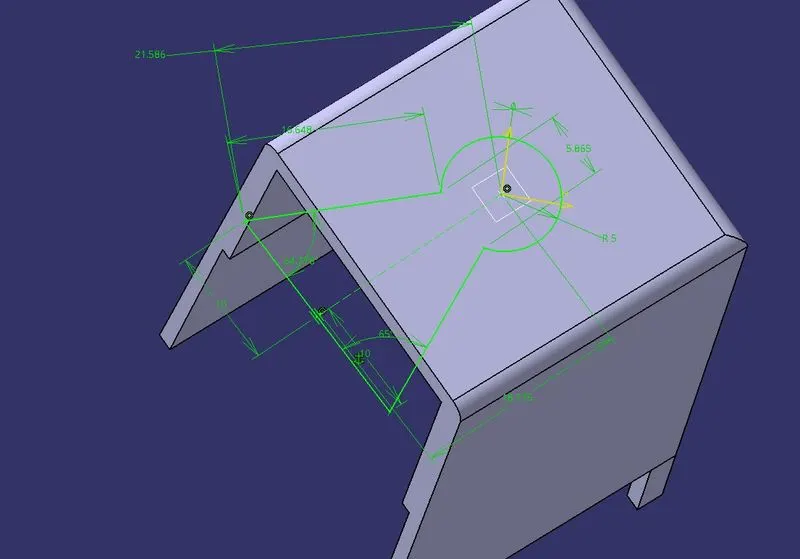
Pic.16 (Upper Cutting Sketch)
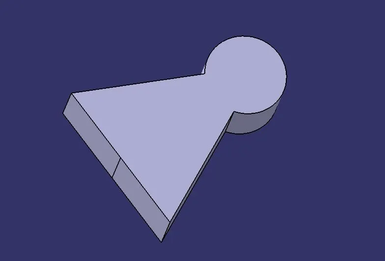
Pic.17 (Upper Cutting)
Final Output:
We have to draft the Dog house outer Inner part according to the mastersection.For Inner part we have include the ribs too using side core axis and draft of about 0.5mm .
For this first we have to remove the upper cutting from the Dog House using Remove command then We have to add Supporting Ribs to Dog House.For the Final Stage We have to Define the Main Part Body and Union trim the Dog House after adding and removing the Supporting ribs and Upper cutting respectively.
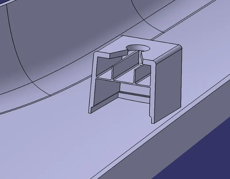
Pic.18
Draft Analysis for the Solid Body:
To perform the draft analysis for the solid part body (which has Dog House on it),used the featured draft analysis tool in the generative shape design workbench. Initially,aligned the compass to the tooling axis and selected the solid part body in the colour bar 0.49deg draft angle provided .The areas which highlighted in Green the below image are cleared in the 0.49deg draft angle.
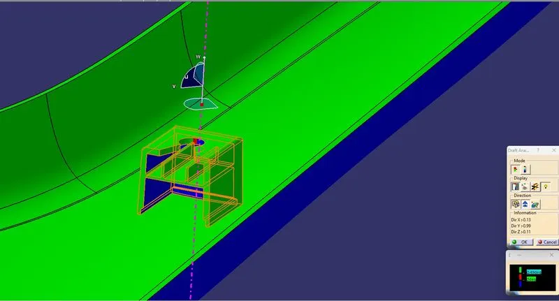
Pic.19 (Outer Draft Analysis using main Tooling Axis)
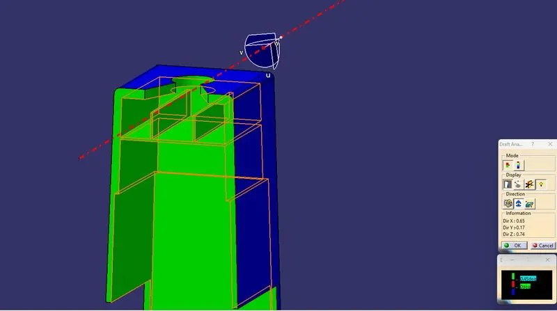
Pic.20 (Inner Draft analysis using Side Core Axis)
Differtent Orientation :
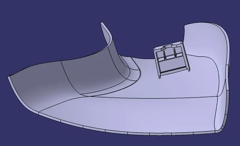
Pic.21 (Front View)
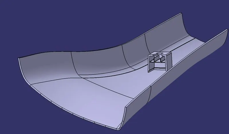
Pic.22 (Isometric View)
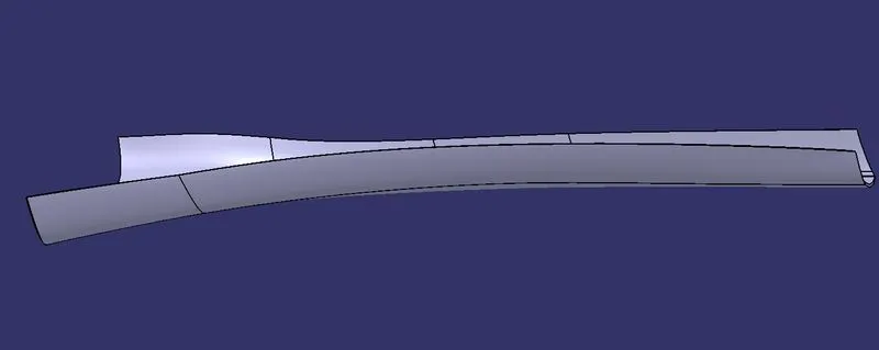
Pic.23 (Side View)
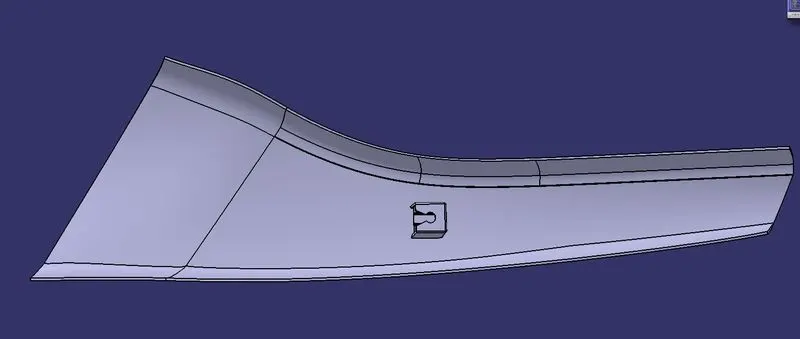
Pic.24 (Top View)
Tree Structure :
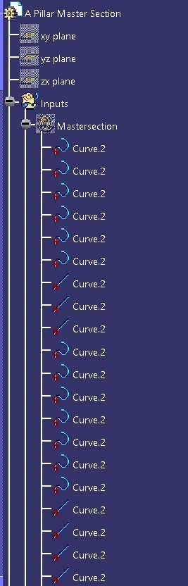
Pic.25
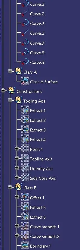
Pic.26
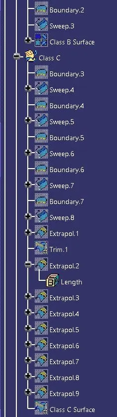
Pic.27
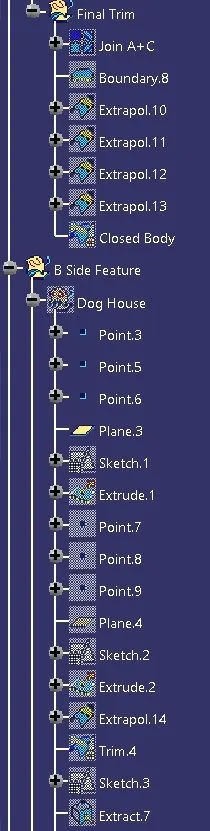
Pic.28
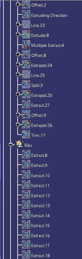
Pic.29
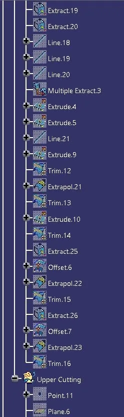
Pic.30
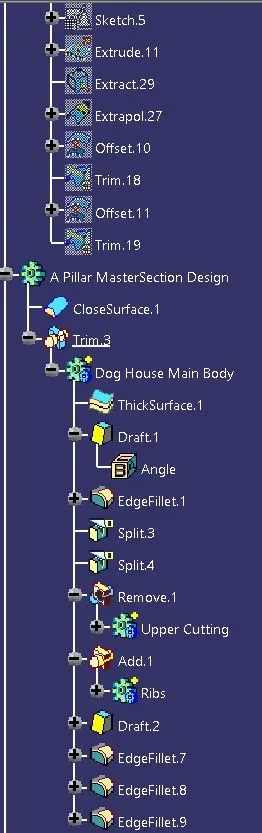
Pic.31
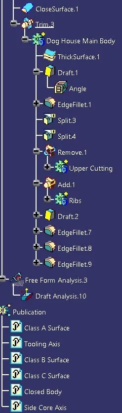
Pic.32
Publication :
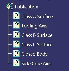
Pic.33