Roof Design
ROOF DESIGN
OBJECTIVE
To create an Assembly by developing the essential flanges for the outer roof and creating the reinforcements. Provide appropriate dimensions and check for Draft analysis. And to Do a curvature study on the roof and perform calculations to determine the position of the Bow-roofs.
The mian objective of this project is to understand the design process to design the roof with all the roof rails and to understand the calculations behind it. We also get to learn about the different tools used in NX cad for designing.
INTRODUCTION
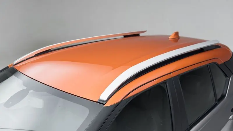
An automobile roof is the portion of an automobile that sits above the passenger compartment, protecting the vehicle occupants from sun, wind, rain, and other external elements. Under the styling surface that is seen from the outside, many other structures under the roof contribute to its strength and stability. The number of such reinforcement structures/supports differs concerning the size of the vehicle. They are primarily installed on flatter areas of the roof to enhance strength.
These are the Front Roof Rail, Rear Roof Rail, Centre Roof Rail, and Bow Roof Design which are given Mastics and spot-welded to roof flanges & ditch areas and improve NVH value by increasing the strength of the roof using mastic sealants.
Pic.1
TYPES OF CAR ROOFS
- Convertible: A convertible, cabriolet, or spyder is a passenger car that can be driven with or without a roof in place.
- Hardtop: A hardtop is a rigid form of automobile roof, which for modern cars is typically constructed from metal. A hardtop roof can be either fixed, detachable for separate storage, or retractable within the vehicle itself.
- Sunroof: An Automotive sunroof is a movable panel that is operable to uncover a window in an automobile roof.which allows light and fresh air into the passenger compartment.
- T-top: A T-top is an automobile roof with a removable panel on each side of a rigid bar running from the center of one structural bar between pillars to the center of the next structural bar. The panels of a traditional T-top are usually made of auto-grade safety glass.
- Targa Top: It is a semi-convertible car body style with a removable roof section and a full-width roll bar behind the seats.
- Vinyl roof: Vinyl roof refers to a vinyl conversion for an automobile’s top. This conversation was originally designed to give the appearance of a convertible to models with a fixed roof but eventually, it evolved into a styling statement in its own right.
DESIGN CONSIDERATION
- Visibility Criteria.
- Head Clearance.
- Curvature Study.
- Heat Distortion and Snow Load Criteria.
- Draft Analysis.
- Safety Parameters.
ROOF CRUSH TEST
Safety point of view vehicle roof plays a very crucial role, especially in rollover kind of accidents, in which the vehicle tips over onto its side of the roof. And vehicle rollover crashes are the cause of many fatalities and head, neck, and spine trauma around the world.
Pic.2

Pic.3
Therefore, passenger safety is also a very important parameter in front of OEMs. It is not only a marketing strategy but also it is an obligation stipulated by international standards that are now placed in several countries, as well as a governmental requirement. For this reason, strength is a very important criterion for designing a vehicle roof.
The strength of the roof structure for occupant protection in real-world rollover crashes, requiring the maximum moving distance of the roof structure should be less than 127 mm (5 in.) when the induced load is 1.5 times the vehicle weight.
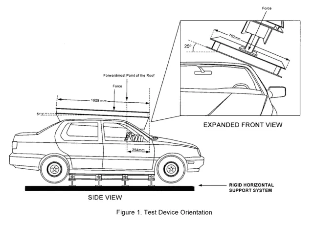
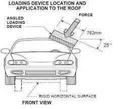
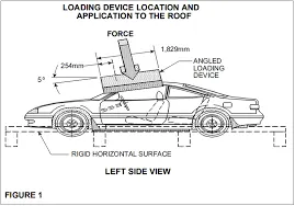
For the test, the passenger car shall be rigidly placed or positioned on a horizontal surface with the doors locked and the window closed. Furthermore, a flat, rigid block with a lower surface a rectangle measuring 30 inches wide by 72 inches long (762mm X 1829mm) shall not move more than 5 inches(127mm), measured as the distance between the original location of the lower surface of the test device and its location as the specified force level is reached, when it is used to apply a force of 1.5 times the unloaded vehicle weight (UVW) or 5000 lbs(22224N), whichever is less, to either side or forward edge of the vehicle.
This test can be conducted on either side of the roof structure, the front left or the front right side but not on both sides in one single test and still meet the requirements of the test. The rigid plate shall not move faster than 0.5 inches/second and the force applied on the plate shall not exceed the lesser of 1.5 times the unloaded vehicle weight (UVW) expressed in kilograms multiplied by 9.8 or 5000lbs (22240N). Also, the direction of the force shall be downward and perpendicular to the lower surface of the rigid plate such that it moves in a straight line without rotation. The duration of the test shall not exceed 120 seconds. The longitudinal axis of the plate is pitched forward at a 5 º angle as viewed from the side of the passenger car as shown in the below figure:
The lateral axis or the roll of the plate is such that it forms a 25 º outboard angle with a horizontal surface as viewed from the front of the passenger car as shown in below figure:
Pic.4
Pic.5
CAR ROLLOVER TEST
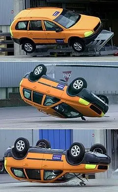
The rollover test is conducted because a rollover is a type of vehicle crash in which a vehicle tips over onto its side or roof. Rollovers have a higher fatality rate than other types of vehicle collisions.
Vehicle rollovers are divided into two categories: tripped and untripped. Tripped rollovers are caused by forces from an external object, such as a curb or a collision with another vehicle. Untripped crashes are the result of steering input, speed, and friction with the ground.
Vehicles which have a higher center of gravity like SUVs or Small Trucks are more prone to rollover. Rollover accidents typically involve a singular vehicle that loses control due to icy or snowy road conditions, soft road shoulders, uneven ground, collision with curbs or guardrails after a vehicle has lost traction, or hitting an obstacle while driving.
During a rollover accident, the regional body distribution of injuries normally affects five main areas: head and neck, thorax, abdomen, upper limbs, and lower limbs. The majority of rollover crash victims sustain multiple injuries throughout these regions with the head and neck being the most vulnerable area. Some of the most common rollover injuries include traumatic brain injury, spinal cord injury, broken bones, cuts, scrapes, and bruises. These injuries are caused by slamming into another vehicle or obstacle, impact with unsecured cargo, contact with broken glass or torn metal, or being tossed within the vehicle or ejected from the vehicle.
Pic.6
PROCEDURE
- Coversion of Surface – Extracting the required surface from the given styling surface using Wave geometry linker.
- Modelling Reinforcement parts – Design ditch area in Roof , Front Roof Rail,Bow Roof 1,Center Reinforcement Roof Rail,Bow Roof 2 and Rear Roof Rail.
- Curvature study and Analysis of Roof – Heat Distortion Test,Snow Load Test,Moment of Inertia , Section Modulus and Draft Analysis.
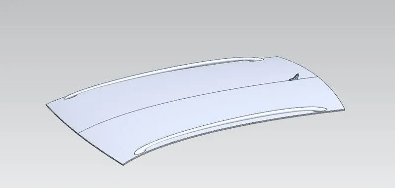
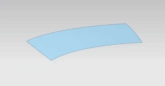
Extraction of surface
The styling team has provided the solid dump outer panel from that we are extracting the surface to model the necessary reinforcements like Ditch area, Front Roof Rail, Bow Roof Rails, Centre Roof, and Rear Roof Rail.
Pic.7
Pic.8
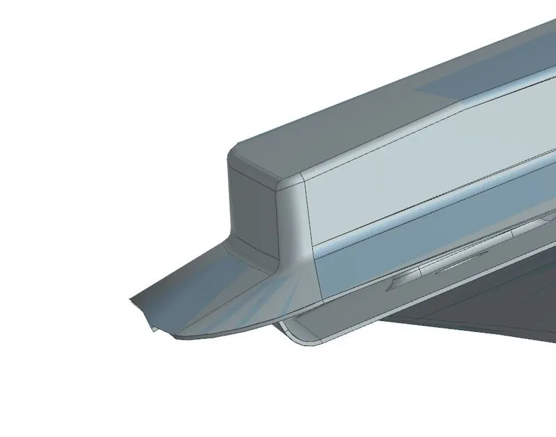
Design a Ditch Area for Outer Roof Panel
The styling team provided the master section for the roof ditch area, front roof rail, and rear roof rail as per the parameter of visibility criteria, headroom clearance, and other important parameter dimensions like fitment of the windshield, sealant rubber, etc. All these data are well calculated in the planning stage to design the peripheral component accordingly. Thus, here designing is done just to replicate those input data considering engineering parameters that should be feasible for manufacturing. Master section of the front and rear section. The Ditch Area is the extended portion of the main Roof concealed by other BIW panels. The rail supports of the roof are attached to the Ditch Area using Spot welds since it is not a styling surface and remains concealed. Headroom Clearance, visibility criteria, and clearance for Windshield and Back door are some of the factors to be considered while designing the Ditch Area. It is given a thickness of 0.75 mm.
- Front Ditch Area-From the dump solid part class, A surface is extracted and the ditch area is developed considering the parameter specified in the following master section.The flange of around 15mm was created with the law extension command, corner relief at rear flanges, and a positive draft of more than 3 degrees considering the drawing operation process. The overall thickness of sheet metal considers 0.75mm throughout.
Pic.9
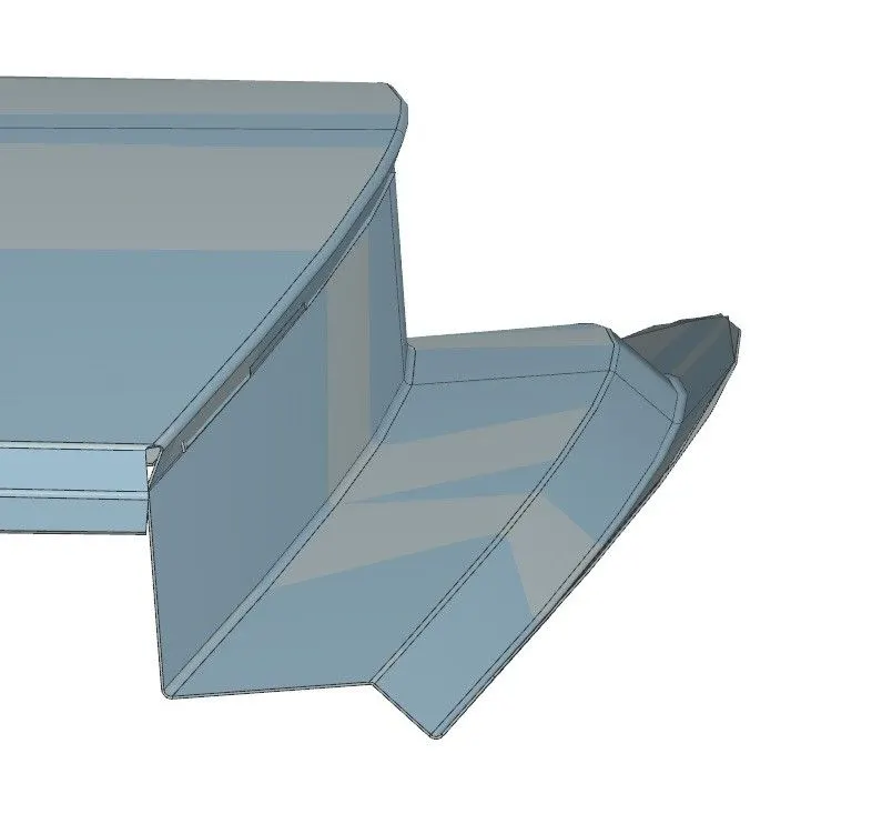
- Rear Ditch Area-The surface is offset from the outer panel to form the ditch area and with the law extension command, corner relief at rear flanges, and positive draft in the required degree considering for the drawing operation process. The overall thickness of sheet metal for the outer panel consider 0.75mm throughout.
Pic.10
FRONT ROOF RAIL
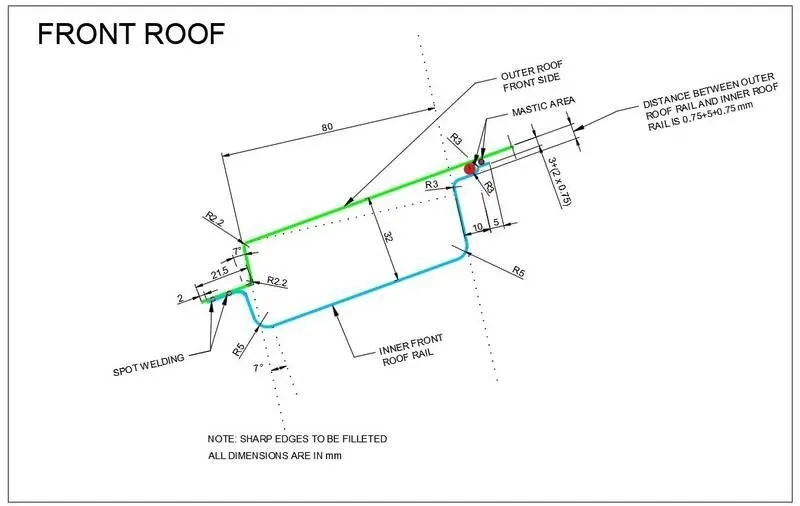
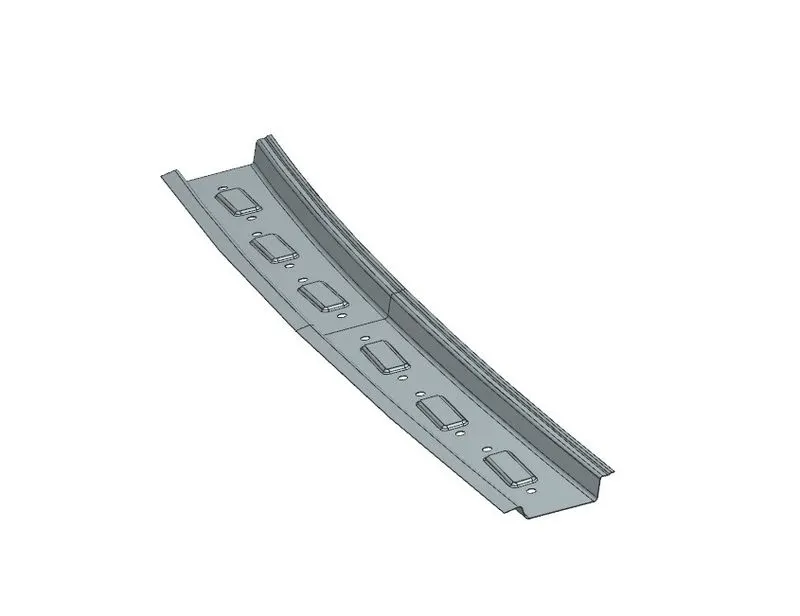
The front rail underpins the rooftop external shell at the front end. It is mounted with support rooftop rail fortification on the two closures. The rails are furnished with embosses to improve the strength over the length and the rail is associated with the external board utilizing mastic sealants on one side and the other joinery is spot welded. It is the support that is joined with the Wind Shield Glass, Body Side Outer, and inner panels. It is usually made from Body Side Outer scrap and therefore the thickness of the rail is 0.75 mm. A draft angle of 3-5 degrees is provided keeping in mind the deep-drawing operation. The Wind Shield end flange is the exact offset of the roof surface. The bottommost flange is decided after taking into consideration the visibility criteria and the Headroom Clearance of the passenger. Spot Welds are applied at the Windshield end of the rail and the other end is joined with the roof using Mastic Sealants which also contributes to increased strength.
Master Section of front roof
Pic.11
Pic.12
REAR ROOF RAIL
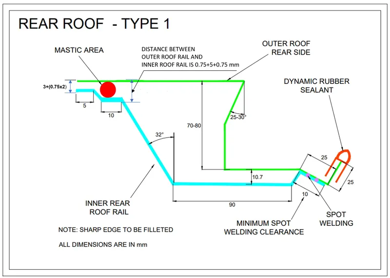
It is the support that is joined to the Back Door and the Body Side Outer and inner panels. It is also usually made from Body Side Outer scrap and therefore the thickness of the rail is 0.65 mm. Similar to the Front Roof Rail design, we have to take into consideration the rear Headroom Clearance and the rear visibility criteria while designing the Rear Roof Rail. Inputs are taken from the rear master section. It is the support that is joined to the Back Door, the Body Side Outer, and the inner panels. It is also usually made from Body Side Outer scrap and therefore the thickness of the rail is 0.75 mm. Similar to the Front Roof Rail design, we have to take into consideration the rear Headroom Clearance and the rear visibility criteria while designing the Rear Roof Rail. Inputs from the backdoor design are also taken to accommodate the required clearance. Spot Welds are applied at the Back door end of the rail and the other end is joined with the roof using Mastic Sealant
Master Section of Rear roof
Pic.13
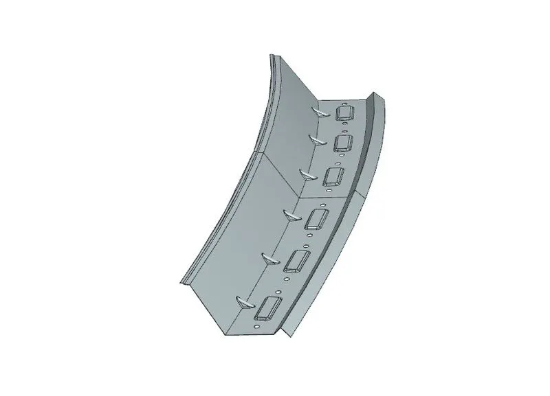
Pic.14
BOW ROOF RAIL
The Bow roofs are given to improve the torsional stiffness and load-bearing capacity of the roof structure. The number of bow roofs provided will depend upon the overall dimensions of the roof. The longer the roof more the bow roofs are integrated into the BIW frame They are attached to the outer panel using mastic sealants. Each mastic point will have up to 80 mm circular effective area. The positioning of bow roofs is done based on a curvature study. The heat distortion criteria and snow load criteria are checked to analyze the position of the bows in various conditions. The thickness of the Bow Roof is 0.75 mm and also mastic area has been created. Two Bow roofs are required for this project so we will have to make 2 bow roofs with the same master section properties.
Master Section of Bow roof 1 & 2
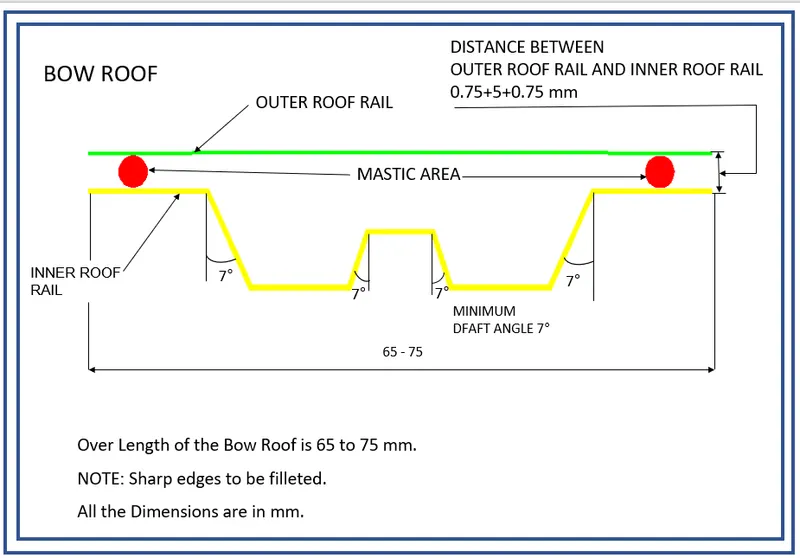
Pic.15
Bow Roof 1
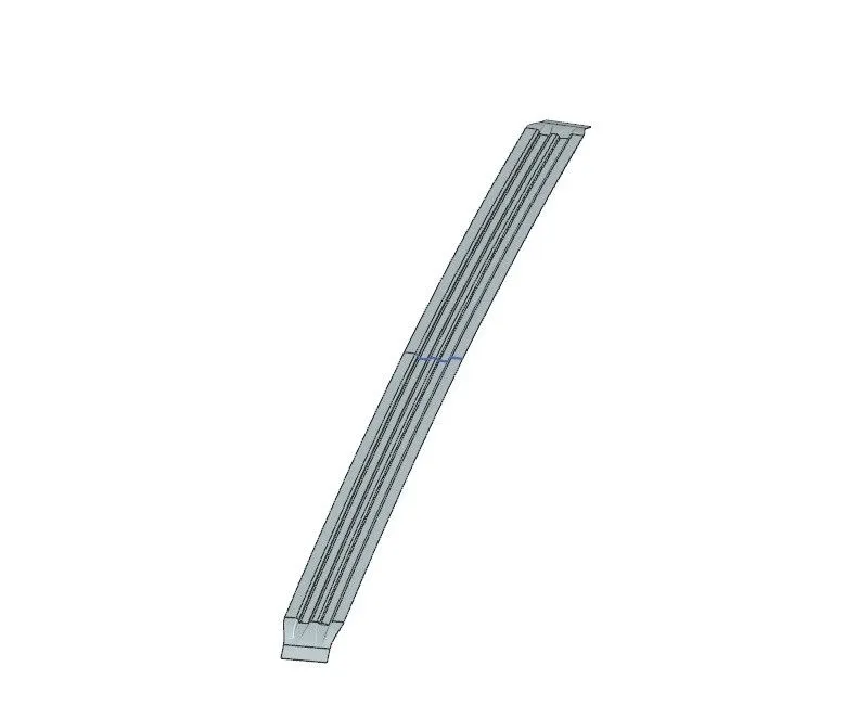
Pic.16
Bow Roof 2
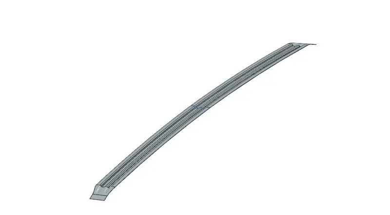
Pic.17
CENTER ROOF RAIL
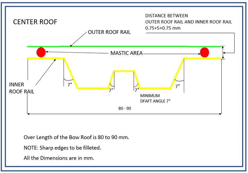
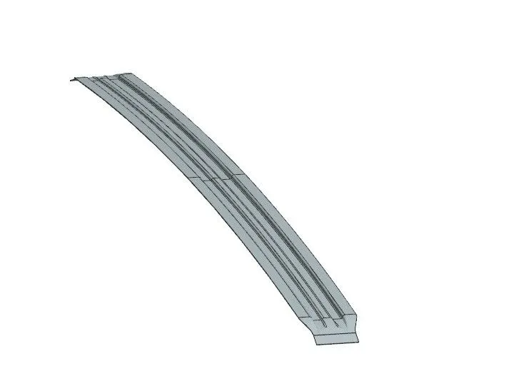
Center roof rail is provided to effectively support the flat area of the roof as it is more susceptible to failure under the action of the load. Usually, the center reinforcement roof rail will be placed at the center of the roof connecting the B pillar support structure which results in added support in the roll-over test. The thickness of the center bow roof is 0.75 mm thickness.
Master Section of Center roof
Pic.17
Pic.18
JOINING PROCESS
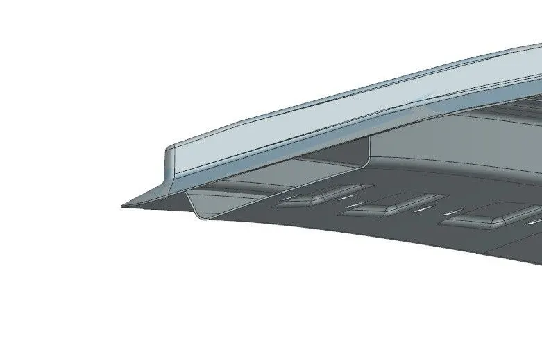
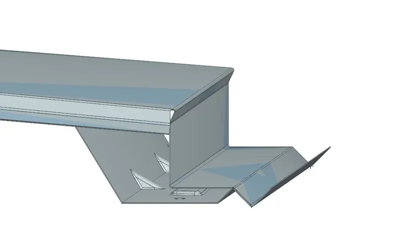
Joining of the Outer Roof Panel and the Front Roof Rail is done by spot welding. The Front Ditch area and the front roof rail are spots welded as it is an easy and efficient process and the welding will be hidden under the windshield area so that it doesn't affect the aesthetic of the car. The same process is done for the joining of the Outer Roof Panel and the Rear Roof Rail, The Rear Ditch area and the Rear Roof Rail are spot welded and they are hidden by the installation of the back door.
Pic.19
Pic.20
Joining of the middle part of the Outer Roof Rail, Bow Roofs, and Center Roof Rails are done by the use of Mastics Sealants. Here we cant use Spot welding because it damages the A-Class area of the Roof. So, mastic sealant is used in this area. For the application of these Mastics, there must be a gap of at least 5mm between the Roof Outer Panel, Bow Roofs, and Center Roof Rail. The ends of the Bow Roofs and Center Roof Rails are joined by spot welding to the Side Ditch area of the Outer Roof Pan.
HEAT DISTORTION CRITERIA
The heat distortion study plays an important role in sheet metal usage. Heat distortion temperature is a temperature limit above which the material cannot be used for structural applications. This study is used to predict the heat distortion temperature at where the material starts to soften when exposed to a fixed load at an elevated temperature. To avoid bending or damage on the roof, based on heat distortion temperature, this study will predict the bow roof position on the roof to strengthen the roof.
W = [1.73 x 10^(-3) x L] + [1.85 x 10^(-8) x (R^2)/t] + [ 1.10x10^(-3) x l] - 2.68
Where,
L = Roof Length in X-Direction[mm](Roof dimension in 0-Y)
R = Roof curvature
R = 2(Rx*Ry)/(Rx+Ry)
Rx = X curvature
Ry = Y curvature
t = Roof plate thickness [mm]
l = Bow Roof Span [mm]
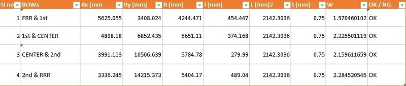
Table.1
Judgment Condition:
OK< 2.7
- Roof Length for styling Surface (L) -For the L we want to take the total of the styling surface and don't include the ditch area as shown below:
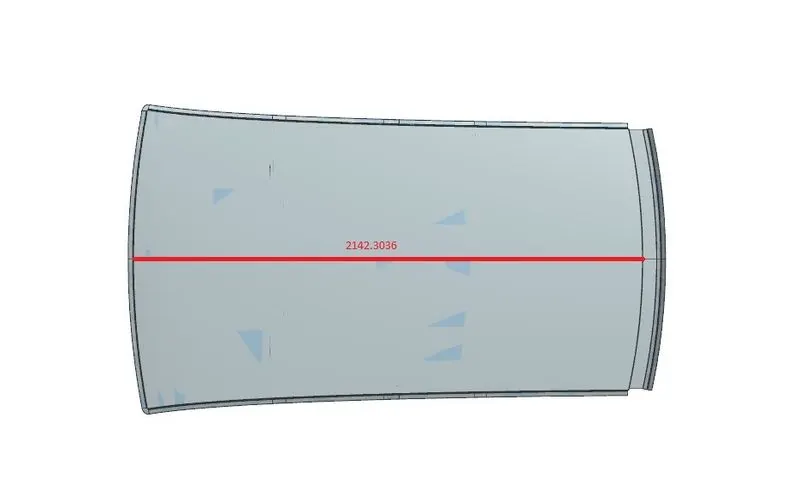
Pic.21
- Bow Roof Span (l)-Here want to take the distance from Front Roof Rail to Bow Roof 1 to find the Bow Roof Span .Similarly, we will measure the distance of the Bow Roof Span (l) between:
Bow Roof 1 to Center Roof Rail.
Center Roof Rail to Bow Roof 2.
Bow Roof 2 to Rear Roof Rail.
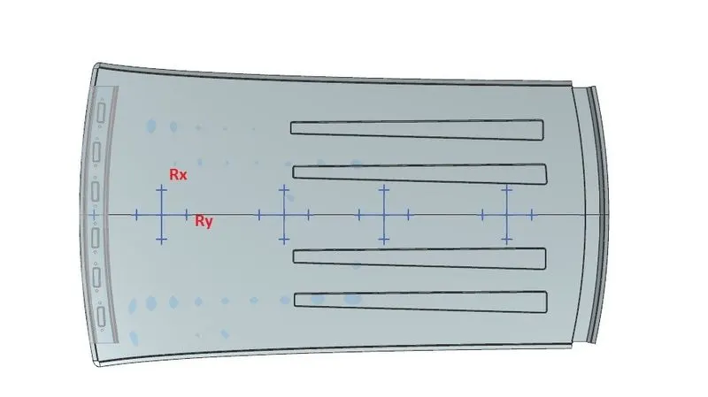
- Rx & Ry (X & Y Curvature)-From the 0-Y axis, at -3Y about a distance of 300mm is drawn parallel on the perpendicular plane as shown in the figure. after that 100 mm lines are offset to either side of the -3Y line. Now center lines are drawn between each adjacent roof rail edge respectively. Intersection points are marked on the sketch and exit the sketch. Make all geometry in construction lines except the points.Project the intersection points in the sketch to the roof surface as shown in the figure.
Join the projected curves using an arc curve and measure the minimum radius and linear dimension as follow & put them into the formula to calculate “W”.
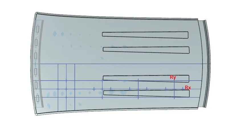
Pic.22
SNOW LOAD CRITERIA
Snow load criteria study is done to check the durability of the roof to withstand snowfall and reflex back to its original shape without any permanent deformation once the load is removed.
Qr = [Iy x t2] / [α x s x [(Rx + Ry)/2]2 x 10-8]
Note: The Qr value given over here is correct. There was a typo error in the formula given in the video.
Where,
α = My x Lx2 x 10-12 , My = Y(Ly-Y)
t = Roof plate thickness [mm]
Ly = Distance between the front and rear roof Rails on the Vehicle along with 0Y[mm]
Length of Roof panel with the center point between Roof rail Front /Rear as the front and rear reference point.
Lx = Distance between the Left and Right end of the roof on the Roof BOW [mm]
The width of the roof panel is exposed on the surface.
Y = Distance front Front Roof Rail to Roof BOW[mm]
s = Distance for which Roof BOW bears divided load [mm]
s = L1/2 + L2/2
Iy = Geometrical moment of inertia of Roof BOW (Y cross-section )[mm4]
Rx = Lateral direction curvature radius of roof panel Y cross-section on Roof BOW [mm]
Roof panel curvature Radius of the Length Lx in Front view
Ry = Longitudinal Direction curvature radius of the Roof panel X cross-section on Roof BOW [mm]
Roof panel X curvature radius of length s in Side view
Judgment condition
Qr ≥ 3.1
250 ≤ s ≤ 380
Lx and Ly
To find the Lx and Ly values take the styling surface of the roof
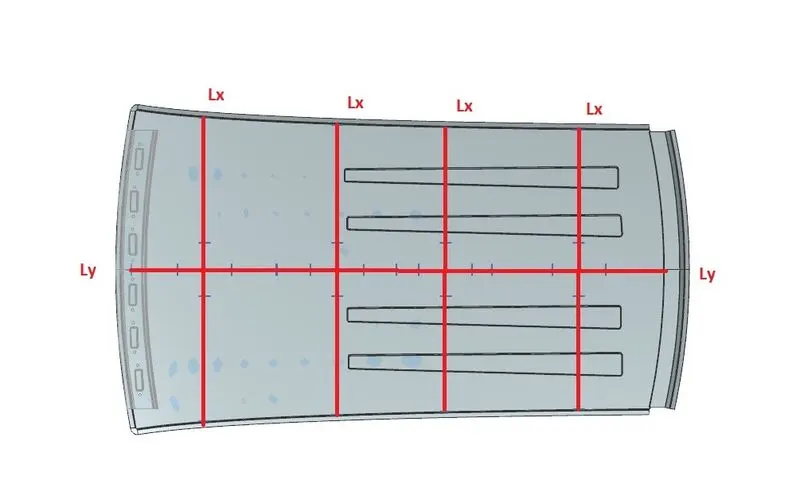
Pic.23
Rx & Ry (X & Y Curvature)
At the 0-Y axis on a perpendicular plane to the roof as shown in fig. draw 100 mm lines offset to either side of the 0Y axis line. Now center lines are drawn between each adjacent roof rail edge respectively. Intersection points are marked on the sketch and exit the sketch. Make all geometry in construction lines except the points.
Project the intersection points in the sketch to the roof surface as shown in fig.
Join the projected curves using an arc curve and measure the minimum radius and linear dimension.
Project the intersection plane bow roof and center roof rail on the horizontal plane to find the moment of inertia of the respective section to find Iy values.
Put all the linear and radial dimensions in the following formula to calculate Qr Value.
Pic.24
Moment of Inertia for the Roof Rails
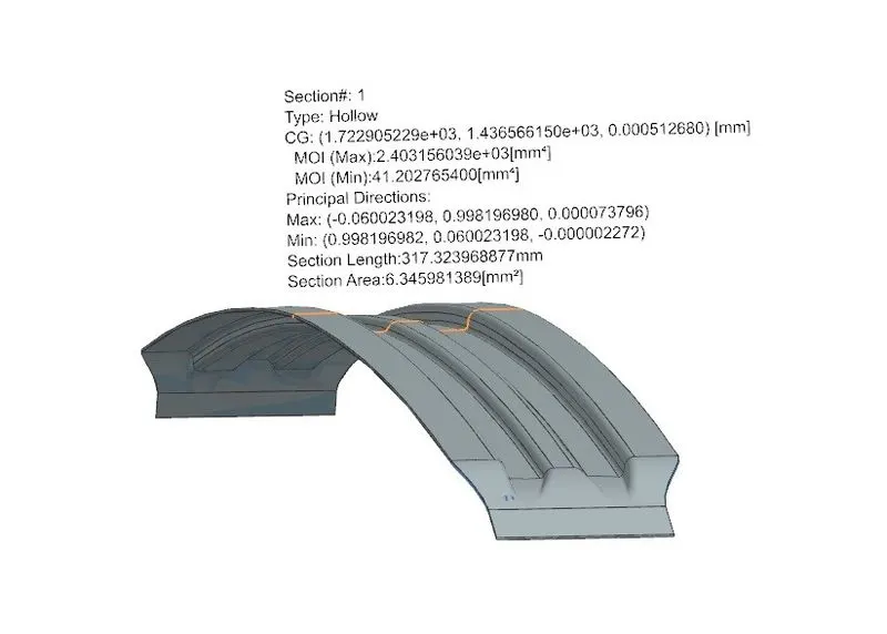
Bow Roof 1
Pic.25
Center Reinforcement Roof
Pic.26
Bow Roof 2
Pic.27

Table.2
- As you know our Roof design does not get satisfying in the snow load prediction. because in some areas the vales were below 3.1
- There are some cases our roof may design may face this kind of problems. To neutralizing this problem we can do some action to get passes in the real-time Snow load test. those are given below.
Redesign the bow to improve the moment of inertia:
- make changes in the position of bow's
- Add an extra bow make some bead or embossed on the roof to strengthening the roof from its displacement.
- passes the test report to the Styling team to change the radius of curvature of the part.
Action:
Here I choose to add some embosses on the roof. so the roof will get passed in the real-time snow load test. the embossed I created will improve the strength of the roof.
Section Modulus
Section modulus is a geometric property for a given cross-section used in the design of beams or flexural members. Other geometric properties used in the design include an area for tension and shear, the radius of gyration for compression, the moment of inertia, and the polar moment of inertia for stiffness. Any relationship between these properties is highly dependent on the shape. There are two types of section moduli
Elastic section modulus
Plastic section modulus
The Elastic Section Modulus is defined as, S = I/y
Where,
S: is the Section Modulus
I: is the second moment of area(or area moment of inertia, not to be confused with the moment of inertia)
y: is the distance from the neutral axis to any given fiber. It is often reported using y = c, where c is the distance from the neutral axis to the most extreme fiber
Bow Roof 1
Pic.28
Moment of Inertia (MAX): Imax = 2403.156 [mm^4]
Moment of Inertia (MIN): Imin = 41.2027[mm^4]
Section Modulus, S = Moment of Inertia (MOI) / Distance between the neutral axis and the end of the object (y)
S = I/y
y = 34.11mm
For Maximum MOI:
S = (2403.156[mm^4]) ÷ (34.11 mm)
Section Modulus: Smax = 70.453 mm^3
For Minimum MOI:
S = (41.2027 [mm^4]) ÷ (34.11 mm)
Section Modulus: Smin = 1.207 mm^3
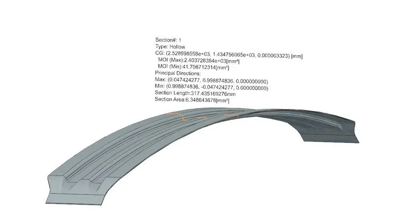
Bow Roof 2
Pic.29
Moment of Inertia (MAX): Imax = 2403.728 [mm^4]
Moment of Inertia (MIN): Imin = 41.708[mm^4]
Section Modulus, S = Moment of Inertia (MOI) / Distance between the neutral axis and the end of the object (y)
S = I/y
y = 34.105 mm
For Maximum MOI:
S = (2403.728 [mm^4]) ÷ (34.105 mm)
Section Modulus: Smax = 70.48 mm^3
For Minimum MOI:
S = (41.708[mm^4]) ÷ (34.105 mm)
Section Modulus: Smin = 1.222 mm^3
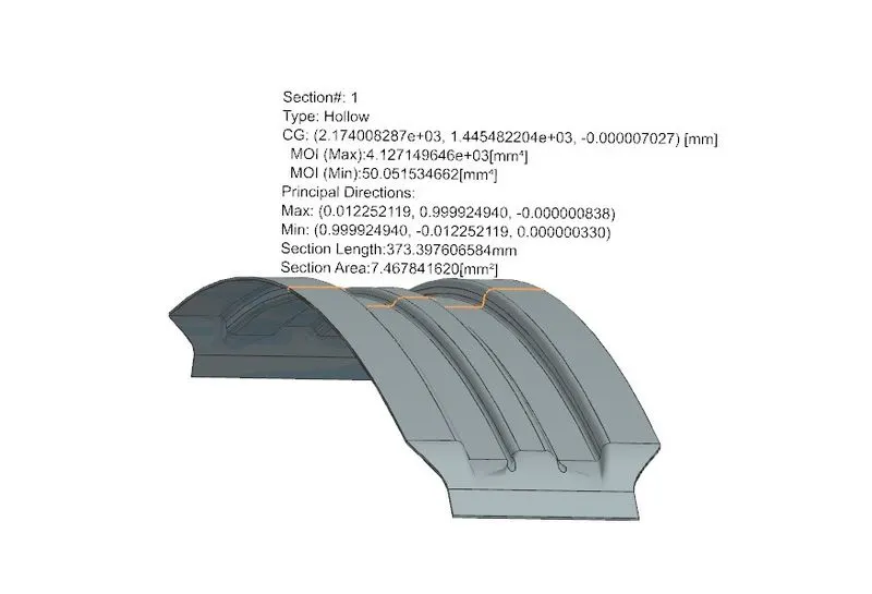
Centre Reinforcement Roof Rail
Pic.30
Moment of Inertia (MAX), Imax = 4127.149 [mm^4]
Moment of Inertia (MIN), Imin = 50.051[mm^4]
Section Modulus, S = Moment of Inertia (MOI) / Distance between the neutral axis and the end of the object (y)
S = I/y
y = 41.105mm
For Maximum MOI,
S = (4127.149 [mm^4]) ÷ (41.105 mm)
Section Modulus : Smax = 100.405 mm^3
For Minimum MOI:
S = (50.051 [mm^4]) ÷ (41.105mm)
Section Modulus : Smin = 1.217mm^3
Front Roof Rail
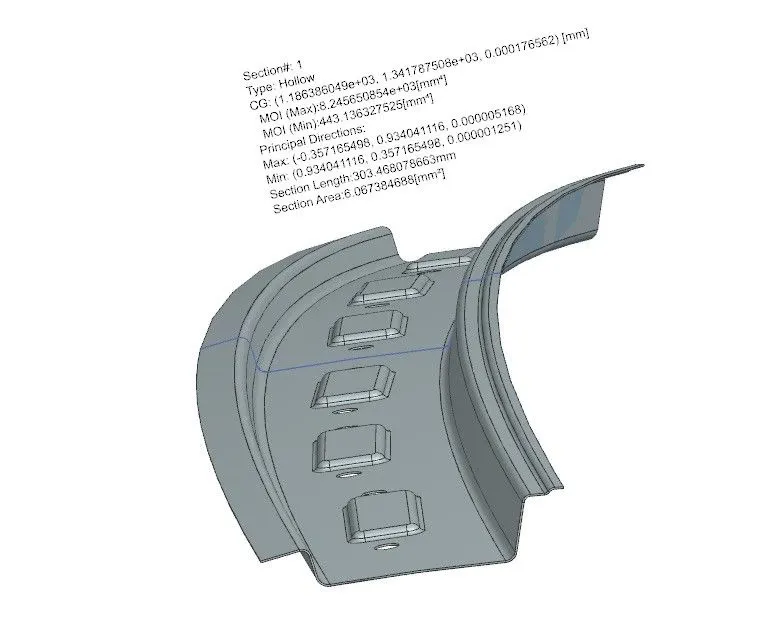
Pic.31
Moment of Inertia (MAX): Imax = 8245.65[mm^4]
Moment of Inertia (MIN): Imin = 443.136 [mm^4]
Section Modulus, S = Moment of Inertia (MOI) / Distance between the neutral axis and the end of the object (y)
S = I/y
y = 61.925mm
For Maximum MOI:
S = (8245.65 [mm^4]) ÷ (61.925 mm)
Section Modulus: Smax =133.155mm^3
For Minimum MOI:
S = (443.136[mm^4]) ÷ (61.925 mm)
Section Modulus: Smin = 7.156 mm^3
Rear Roof Rail
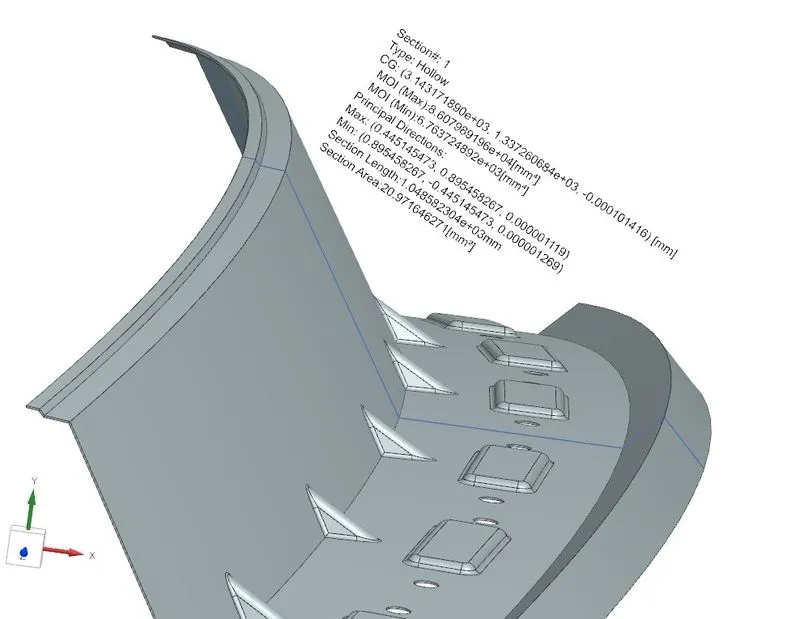
Pic.32
Moment of Inertia (MAX): Imax =86079.891 [mm^4]
Moment of Inertia (MIN): Imin = 6763.724 [mm^4]
Section Modulus, S = Moment of Inertia (MOI) / Distance between the neutral axis and the end of the object (y)
S = I/y
y = 109.985 mm
For Maximum MOI,
S = (86079.891[mm^4]) ÷ (109.985mm)
Section Modulus: Smax = 782.65 mm^3
For Minimum MOI:
S = (6763.724 [mm^4]) ÷ (109.985 mm)
Section Modulus: Smin = 61.496 mm^3
Draft Analysis
The Draft Analysis command enables you to detect if the part you drafted will be easily removed. This type of analysis is performed based on color ranges identifying zones on the analyzed element where the deviation from the draft direction at any point, corresponds to specified values.
A minimum draft angle of 7° is considered for analysis. The green color infers the parts that all face along the tooling direction has a positive draft angle greater than 7° and passed in analysis.
Front Roof Rail Draft Analysis
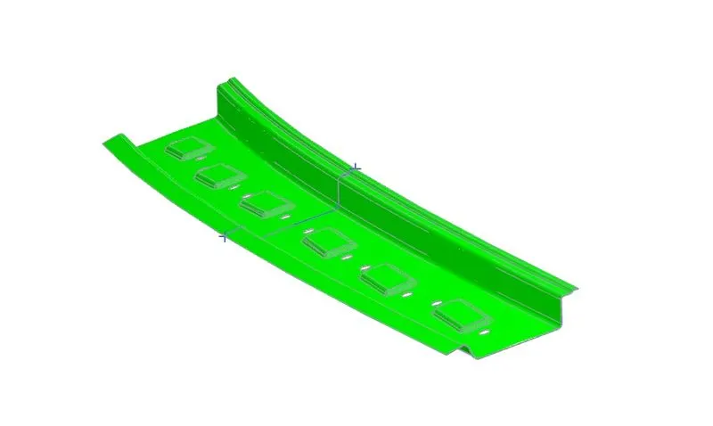
Pic.33
Rear Roof Rail Draft Analysis
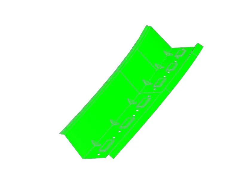
Pic.34
Bow Roof 1 Draft Analysis
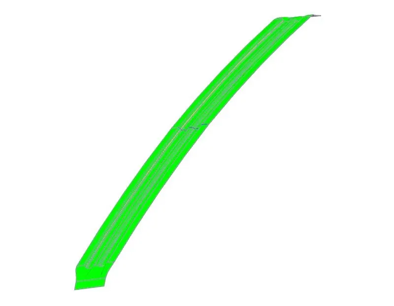
Pic.35
Bow Roof 2 Draft Analysis
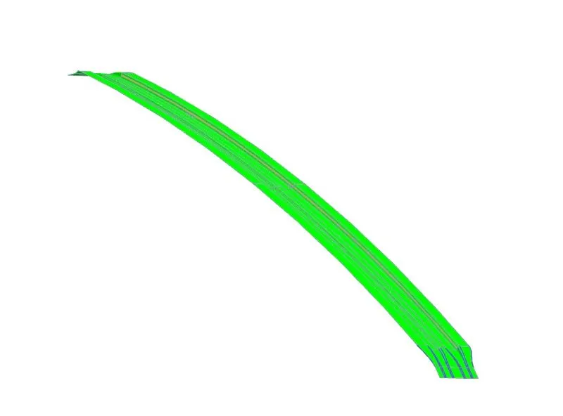
Pic.36
Center Reinforcement Roof Draft Analysis
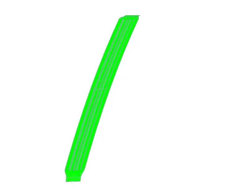
Pic.37
Roof Outer Panel Draft Analysis
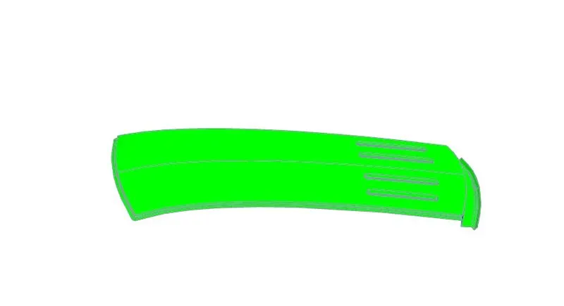
Pic.38
ROOF IN DIFFERENT VIEWS
Top View
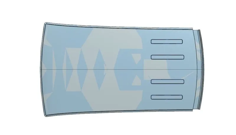
Pic.39
Isometric View
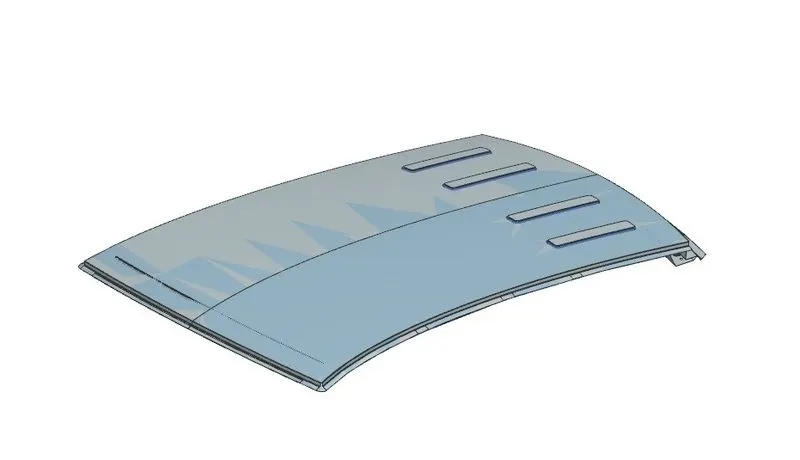
Pic.40
Bottom View
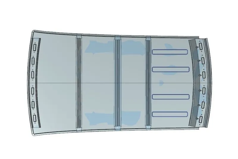
Pic.41
Side View
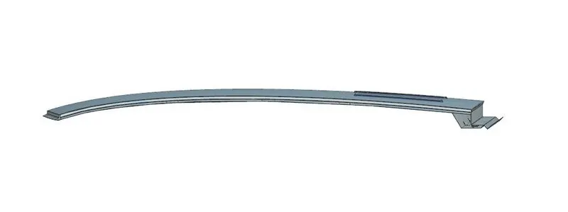
Pic.42
CONCLUSION
From this challenge, I have learned the Roof design using required reinforcements and Ditch Area for the Roof and developed from the given styling. The curvature study was done after performing calculations for the Heat Distortion and Snow load conditions with the position criterias met for all reinforcements.
Then, the Section Inertia study was conducted and a Draft Analysis was done for each reinforcement successfully.