Fuel cell powered model
Question
For the 6 kW 45 Vdc Fuel Cell Stack built-in model in Matlab,
a.Explain the working priniciple of the model in detail
b.Simulate the model and explain the results
c.Explain the voltage and current characteristics in your resultant graph
Your Answers
For the 6 kW 45 Vdc Fuel Cell Stack built-in model in Matlab,
a.Explain the working priniciple of the model in detail
b.Simulate the model and explain the results
c.Explain the voltage and current characteristics in your resultant graph
a.Explain the working priniciple of the model in detail:-
A fuel cell is a device that generates electricity by a chemical reaction. Every fuel cell has two electrodes called, respectively, the anode and cathode. The reactions that produce electricity take place at the electrodes.
Every fuel cell also has an electrolyte, which carries electrically charged particles from one electrode to the other, and a catalyst, which speeds the reactions at the electrodes.
Hydrogen is the basic fuel, but fuel cells also require oxygen. One great appeal of fuel cells is that they generate electricity with very little pollution–much of the hydrogen and oxygen used in generating electricity ultimately combine to form a harmless byproduct, namely water.
One detail of terminology: a single fuel cell generates a tiny amount of direct current (DC) electricity. In practice, many fuel cells are usually assembled into a stack. Cell or stack, the principles are the same.
How do fuel cells work?
The purpose of a fuel cell is to produce an electrical current that can be directed outside the cell to do work, such as powering an electric motor or illuminating a light bulb or a city. Because of the way electricity behaves, this current returns to the fuel cell, completing an electrical circuit. (To learn more about electricity and electric power, visit "Throw The Switch" on the Smithsonian website The chemical reactions that produce this current are the key to how a fuel cell works.
There are several kinds of fuel cells, and each operates a bit differently. But in general terms, hydrogen atoms enter a fuel cell at the anode where a chemical reaction strips them of their electrons. The hydrogen atoms are now "ionized," and carry a positive electrical charge. The negatively charged electrons provide the current through wires to do work. If alternating current (AC) is needed, the DC output of the fuel cell must be routed through a conversion device called an inverter.
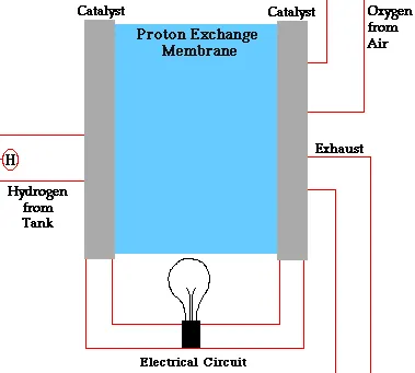 Graphic by Marc Marshall, Schatz Energy Research Center |
Oxygen enters the fuel cell at the cathode and, in some cell types (like the one illustrated above), it there combines with electrons returning from the electrical circuit and hydrogen ions that have traveled through the electrolyte from the anode. In other cell types the oxygen picks up electrons and then travels through the electrolyte to the anode, where it combines with hydrogen ions.
The electrolyte plays a key role. It must permit only the appropriate ions to pass between the anode and cathode. If free electrons or other substances could travel through the electrolyte, they would disrupt the chemical reaction.
Whether they combine at anode or cathode, together hydrogen and oxygen form water, which drains from the cell. As long as a fuel cell is supplied with hydrogen and oxygen, it will generate electricity.
Even better, since fuel cells create electricity chemically, rather than by combustion, they are not subject to the thermodynamic laws that limit a conventional power plant (see "Carnot Limit" in the glossary). Therefore, fuel cells are more efficient in extracting energy from a fuel. Waste heat from some cells can also be harnessed, boosting system efficiency still further.
So why can't I go out and buy a fuel cell?
The basic workings of a fuel cell may not be difficult to illustrate. But building inexpensive, efficient, reliable fuel cells is a far more complicated business.
Scientists and inventors have designed many different types and sizes of fuel cells in the search for greater efficiency, and the technical details of each kind vary. Many of the choices facing fuel cell developers are constrained by the choice of electrolyte. The design of electrodes, for example, and the materials used to make them depend on the electrolyte. Today, the main electrolyte types are alkali, molten carbonate, phosphoric acid, proton exchange membrane (PEM) and solid oxide. The first three are liquid electrolytes; the last two are solids.
The type of fuel also depends on the electrolyte. Some cells need pure hydrogen, and therefore demand extra equipment such as a "reformer" to purify the fuel. Other cells can tolerate some impurities, but might need higher temperatures to run efficiently. Liquid electrolytes circulate in some cells, which requires pumps. The type of electrolyte also dictates a cell's operating temperature–"molten" carbonate cells run hot, just as the name implies.
Each type of fuel cell has advantages and drawbacks compared to the others, and none is yet cheap and efficient enough to widely replace traditional ways of generating power, such coal-fired, hydroelectric, or even nuclear power plants.
The following list describes the five main types of fuel cells. More detailed information can be found in those specific areas of this site.
Different types of fuel cells.
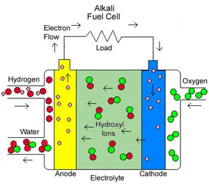 Drawing of an alkali cell. |
Alkali fuel cells operate on compressed hydrogen and oxygen. They generally use a solution of potassium hydroxide (chemically, KOH) in water as their electrolyte. Efficiency is about 70 percent, and operating temperature is 150 to 200 degrees C, (about 300 to 400 degrees F). Cell output ranges from 300 watts (W) to 5 kilowatts (kW). Alkali cells were used in Apollo spacecraft to provide both electricity and drinking water. They require pure hydrogen fuel, however, and their platinum electrode catalysts are expensive. And like any container filled with liquid, they can leak.
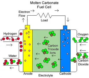 Drawing of a molten carbonate cell |
Molten Carbonate fuel cells (MCFC) use high-temperature compounds of salt (like sodium or magnesium) carbonates (chemically, CO3) as the electrolyte. Efficiency ranges from 60 to 80 percent, and operating temperature is about 650 degrees C (1,200 degrees F). Units with output up to 2 megawatts (MW) have been constructed, and designs exist for units up to 100 MW. The high temperature limits damage from carbon monoxide "poisoning" of the cell and waste heat can be recycled to make additional electricity. Their nickel electrode-catalysts are inexpensive compared to the platinum used in other cells. But the high temperature also limits the materials and safe uses of MCFCs–they would probably be too hot for home use. Also, carbonate ions from the electrolyte are used up in the reactions, making it necessary to inject carbon dioxide to compensate.
Phosphoric Acid fuel cells (PAFC) use phosphoric acid as the electrolyte. Efficiency ranges from 40 to 80 percent, and operating temperature is between 150 to 200 degrees C (about 300 to 400 degrees F). Existing phosphoric acid cells have outputs up to 200 kW, and 11 MW units have been tested. PAFCs tolerate a carbon monoxide concentration of about 1.5 percent, which broadens the choice of fuels they can use. If gasoline is used, the sulfur must be removed. Platinum electrode-catalysts are needed, and internal parts must be able to withstand the corrosive acid.
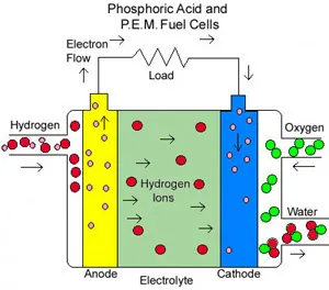 Drawing of how both phosphoric acid and PEM fuel cells operate. |
Proton Exchange Membrane (PEM) fuel cells work with a polymer electrolyte in the form of a thin, permeable sheet. Efficiency is about 40 to 50 percent, and operating temperature is about 80 degrees C (about 175 degrees F). Cell outputs generally range from 50 to 250 kW. The solid, flexible electrolyte will not leak or crack, and these cells operate at a low enough temperature to make them suitable for homes and cars. But their fuels must be purified, and a platinum catalyst is used on both sides of the membrane, raising costs.
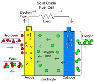 Drawing of a solid oxide cell |
Solid Oxide fuel cells (SOFC) use a hard, ceramic compound of metal (like calcium or zirconium) oxides (chemically, O2) as electrolyte. Efficiency is about 60 percent, and operating temperatures are about 1,000 degrees C (about 1,800 degrees F). Cells output is up to 100 kW. At such high temperatures a reformer is not required to extract hydrogen from the fuel, and waste heat can be recycled to make additional electricity. However, the high temperature limits applications of SOFC units and they tend to be rather large. While solid electrolytes cannot leak, they can crack.
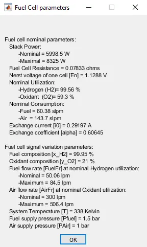
the Proton Exchange Membrane (PEM) Fuel Cell Stack model feeding an average value 100Vdc DC/DC converter.
Olivier Tremblay, Njoya Motapon Souleman, Louis-A. Dessaint (Ecole de technologie superieure, Montreal)
Description
The nominal Fuel Cell Stack voltage is 45Vdc and the nominal power is 6kW. The converter is loaded by an RL element of 6kW with a time constant of 1 sec. During the first 10 secs, the utilization of the hydrogen is constant to the nominal value (Uf_H2 = 99.56%) using a fuel flow rate regulator. After 10 secs, the flow rate regulator is bypassed and the rate of fuel is increased to the maximum value of 85 lpm in order to observe the variation in the stack voltage. That will affect the stack efficiency, the fuel consumption and the air consumption.
Fuel cell voltage, current, DC/DC converter voltage and DC/DC converter current signals are available on the Scope2. Fuel flow rate, Hydrogen and oxygen utilization, fuel and air consumption, and efficiency are available on the Scope1.
Simulation
At t = 0 s, the DC/DC converter applies 100Vdc to the RL load (the initial current of the load is 0A). The fuel utilization is set to the nominal value of 99.56%. The current increases to the value of 133A. The flow rate is automatically set in order to maintain the nominal fuel utilization. Observe the DC bus voltage (Scope2) which is very well regulated by the converter. The peak voltage of 122Vdc at the beginning of the simulation is caused by the transient state of the voltage regulator.
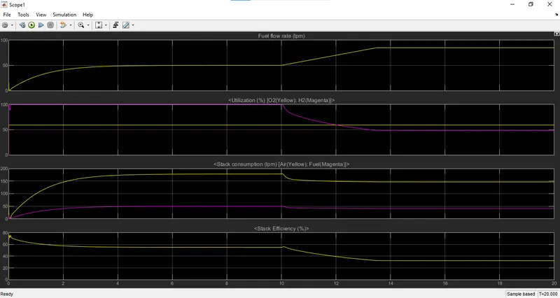
At t = 10 s, the fuel flow rate is increased from 50 liters per minute (lpm) to 85 lpm during 3.5 s reducing by doing so the hydrogen utilization. This causes an increasing of the Nernst voltage so the fuel cell current will decrease. Therefore the stack consumption and the efficiency will decrease (Scope1).
Notes
1) You can vary more than 7 signals by checking the checkbox in the "Signal variation" tab of the Simulink® mask. Refer to documentation for more information.
2) A simplified version of the model allows simulating the fuel cell with less parameters using only the V-I curves. Select "Model detailed Level" to "Simplified". Note that the signal variation is not available in this mode; hence the Fuel flow rate input is not available anymore. Also the utilization, the stack consumption and the efficiency are 0 for the "Simplified" mode.
Library
Simscape / Electrical / Specialized Power Systems / Electric Drives / Extra Sources
Description
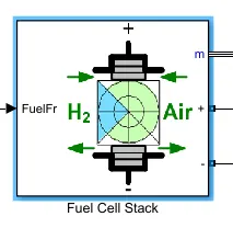
The Fuel Cell Stack block implements a generic model parameterized to represent most popular types of fuel cell stacks fed with hydrogen and air.
The block represents two versions of the stack model: a simplified model and a detailed model. You can switch between the two models by selecting the level in the mask under Model detail level in the block dialog box.
Simplified Model
This model is based on the equivalent circuit of a fuel cell stack shown below:
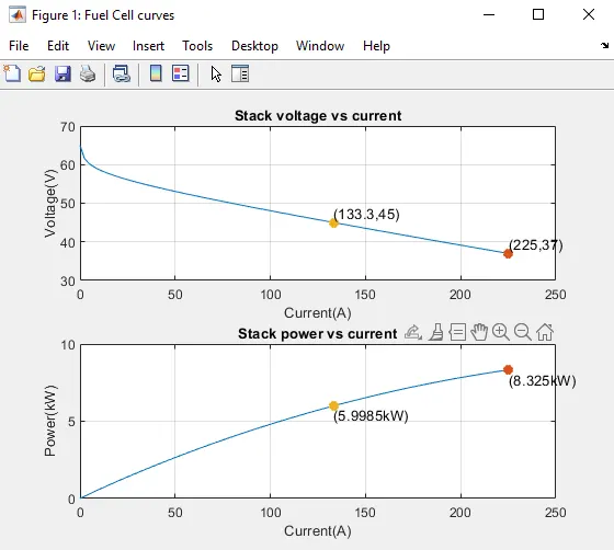
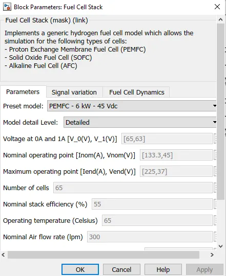
The simplified model represents a particular fuel cell stack operating at nominal conditions of temperature and pressure. The parameters of the equivalent circuit can be modified based on the polarization curve obtained from the manufacturer datasheet. You just have to input in the mask the value of the voltage at 0 and 1 A, the nominal and the maximum operating points, for the parameters to be calculated. A diode is used to prevent the flow of negative current into the stack. A typical polarization curve consists of three regions:
The first region represents the activation voltage drop due to the slowness of the chemical reactions taking place at electrode surfaces. Depending on the temperature and operating pressure, type of electrode, and catalyst used, this region is more or less wide. The second region represents the resistive losses due to the internal resistance of the fuel cell stack. Finally, the third region represents the mass transport losses resulting from the change in concentration of reactants as the fuel is used.
Boost Converter
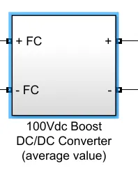
Description
A boost converter is a DC/DC power converter which steps up voltage from its input (source) to its output (load). In continuous conduction mode (current through the inductor never falls to zero), the theoretical transfer function of the boost converter is:
where is the duty cycle.
In this example, the converter is feeding an RC load from a 24 V source and the PWM frequency is set to 20 kHz.
Simulation
Run the simulation and observe waveforms on Scope. Verify that the mean value of the load voltage (Vout) is very close to the theoretical value of: Vout = 24 / (1 - 0.5) = 48 V.
Flow rate regulator
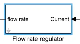
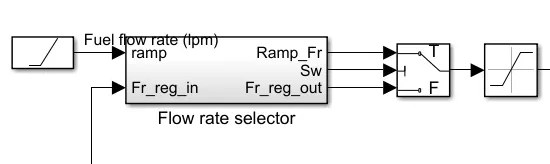
the first 10 secs, the utilization of the hydrogen is constant to the nominal value (Uf_H2 = 99.56%) using a fuel flow rate regulator. After 10 secs, the flow rate regulator is bypassed and the rate of fuel is increased to the maximum value of 85 lpm in order to observe the variation in the stack voltage
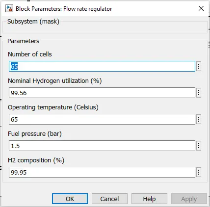
Flow rate regulator and flow rate selector: This is used to control the flow rate of fuel into the fuel cell. It takes the feedback of how much current the fuel cell is producing and decides the flow rate accordingly. This is then fed into the flow rate selector. A reference input of the UDDS drive cycle (current vs time) has been given as a modification to the model for better analysis, as the original model only had a ramp block that was ramping up the flow rate by 10. The drive cycle is originally for 1369 seconds, but running it for 200 seconds will be sufficient for analysis needed for this project.
Dc Bus Voltage and current
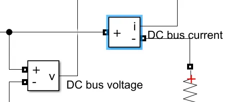
Ideal current measurement. The Output signal parameter is disabled when the block is not used in a phasor simulation. The phasor simulation is activated by a Powergui block placed in the model.
Ideal voltage measurement. The Output signal parameter is disabled when the block is not used in a phasor simulation. The phasor simulation is activated by a Powergui block placed in the mode
Scope 1
Results:-
- In scope1 the fuel flow rate became stable at 50 before 10 sec and after 10 sec went to 90 due to increase in fuel flow rate
- At t = 10 s, the fuel flow rate is increased from 50 liters per minute (lpm) to 85 lpm during 3.5 s reducing by doing so the hydrogen utilization , oxygen remains constant
- stack consumption has reduced to 150 after 10 sec whereas fuel has also reduced little bit
- In stack efficiency before the percentage was near 55 and after 10 sec it went down to 45 after increase in fuel rate.
c.Explain the voltage and current characteristics in your resultant graph
Scope 2
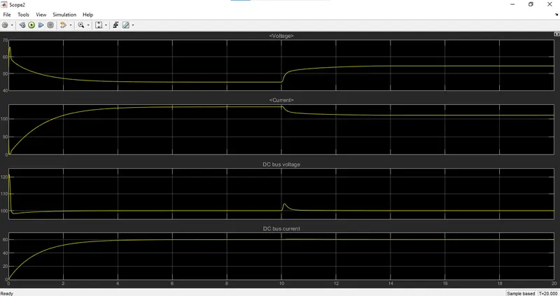
- In this graph the voltage gets constant at 45v before 10 sec and gets increased to 55v after 10 sec due to increase in fuel flow rate
- the currents gets also reduced after 10 sec and become constant at 100A
- due to dc bus voltage, the voltage doesn't get much fluctuation ,only small fluctuation can be seen at 10 sec and the voltage gets stable at 100v.
- the dc current shows a good constant output at 60A, no fluctuation can be seen due to dc-dc booster control system.