To understand Induction motor Characteristics week 8
AIM:- To understand Induction motor Characteristics
Objective:-
- To find the similarities between induction motor operation & clutch.
- Calculate the starting time of a drive.
- Obtain the equilibrium points and determine the stability of the following equations for the motor.
#Ques 1- How induction motor operation is similar to the clutch?
Clutch - A clutch is a mechanical device that engages and disengages the power transmission from the driving shaft to the driven shaft.
- It's a device that actually connects and disconnects the two rotating shafts
- Where one shaft is connected to the engine which is the driving shaft and provided the output power to the Driven shaft which is connected to the differential.
- Clutch connects the two shafts so they may be locked together but they are spinning at different speeds because of the slip
- Clutch slipping simply means when your clutch is engaging and disengaging and no power is delivered to the wheels and as a result, the car will not move forward.
Relation between Speed of driving shaft & driven shaft due to slip losses is given by,
`ω2 = ω1(1-s)`
where,
ω2 = Driving shaft speed
ω2 = Driven shaft speed
s = Slip loss
Power on Driving shaft = P1 = Tω1
Power on Driven shaft = P2 = Tω2 = Tω1(1-s)
Power Loss = PL = Input power - Output power
PL = Tω1 - Tω2
pL = Tω1 - Tω1(1-s)
PL = Tω1(s)
Power Ratio = P1:PL:P2 = Tω1 : Tω1(s) : Tω1(1-s)
Power Ratio = 1 : s : 1-s ------------- 1
Induction Motor - An induction motor is an AC electric motor in which the electric current the rotor needed to produce torque is obtained by electromagnetic induction from the magnetic field of the stator winding.
Torque Slip Characteristics of Induction Motor-
- The Torque slip characteristic is a curve plotted between the torque and the slip of the induction motor. It also gives the relationship between torque and slip.
- Induction Motor having a similar operation to a mechanical clutch.
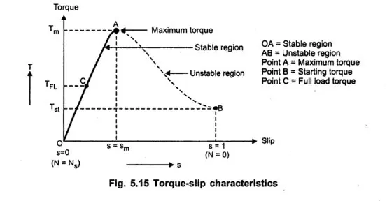
- When the rotor speed is equal to the synchronous speed, the slip is zero. In this condition, the torque is zero from the above equation. Hence, the torque-slip curve starts from zero
- When the rotor speed is not equal to the synchronous speed but near to the synchronous speed, the slip is very low
- If slip increases with the increase in load, the torque reaches the maximum value. At this time, slip is equal to the rotor resistance and rotor reactance. The maximum torque is also known as the pull-out torque or break down torque.
- If further increase in the slip with an increase in load beyond the maximum torque, the torque starts to decrease.
Now, the rotor speed is given by reducing the slip from the stator synchronous speed
ωm = ωms(1-s)
where,
ωm = Rotor speed
ωms = Stator synchronous speed
s = Slip
Power losses in the induction motor can be calculated as,
Power Losses ratio = Pr : Pcr : Pm
Power Losses ratio = 1 : s : 1-s ------------2
Similarities between Induction motor operation is similar to the Clutch
- Induction Motor similar to an operation of a mechanical clutch, where the load is engaged when speed rises. The load torque is also higher than the motor torque, thus limits the speed by not reaching infinite values and also does not reduce the spinning speed of the motor to 0.
- The above equation is very similar to the clutch's speed transmission equation, in both cases the Slip is there and it is the loss that we see in the transmission of power.
- we can conclude from these equations that the Induction motor operates in a similar way of transmitting the speed and torque from the stator to the rotor.
#Ques 2- Calculate the starting time of a drive.
Given-
J = Moment of inertia = 10 kg-m2,
Tm = Motor Torque = 15 + 0.5ωm,
Tl = Load Torque = 5+0.6ωm
t = starting time of motor (calculate)
ωm = synchronous speed
solution-
at ideal condition Tm = Tl
so, on comparing,
15 + 0.5ωm = 5+0.6ωm
wm = 100 rad/sec
and we know, study state equation,
`Tm = Tl + J((dω_m)/dt)`
Now we calculate the starting time by putting the steady-state equation,
- on substituting the values,
15 + 0.5ωm = 5+0.6ωm + `10((dωm)/dt)`
`15 - 10 + 0.5ω_m - 0.6ω_m = 10((dω_m)/dt)`
`dt = 1/(1-0.01ω_m) dω_m`
Now we calculate the starting time by integrating the equation,
`int dt = int 1/(1-0.01ω_m) dω_m`
- The upper and lower limits are the initial and end of transient state of the motor,
which the motor attains at its steady state speed,
`int_(ω_ml)^(ω_m u) dt = int_(ω_m l)^(ω_m u) 1/(1-0.01ω_m) dω_m`
ωml = 0 (initial state - lower limit)
ωmu = 95% of ωm = `95/100 times 100` = 95 (transient state - upper limit)
- on putting the upper and lower limit to the equation
`int_(0)^(95) dt = int_(0)^(95) 1/(1-0.01ω_m) dω_m`
- to solve the equation we use the formula,
`int 1/x dx = ln |x| + c`
on calculating the equation we get,
`t = -1/0.01 ln(1-0.01ωm) + c|_0^95`
on putting the initial conditions, we get
ωm = 0 we get c = 0
now, on solving the equation using upper and lower limit we get,
`t = -1/0.01 times -2.9957`
`t = 299.57 approx 300sec`
Result - hence, we get the starting time of the motor `t approx 300s`
#Ques 3- Obtain the equilibrium points and determine the stability of the following equations for the motor.
Given-
Tm=(1+2ωm)
Tl= 3 √ωm
Find- Equilibrium points and determine the stability,
Solution-
at Steady state condition
Tm = Tl
on comparing,
1+2ωm = 3 x √ωm
2ωm - 3 x √ωm + 1 = 0
so, we get the quadratic equation,
on solving it using quadratic equation `ax^2 + bx +c = 0`
we get values,
√ωm = (i)0.25 rad/s, (ii) 1 rad/sec
we know the stability condition is
`(dT_l)/(dw) - (dT_m)/(dw) gt 0`
on differentiating Tl & Tm
`(dT_l)/dt = 3/(2sqrt(ω_m))` `
`(dT_m)/(dw) = 2`
on substituting the values in stability equation,
`3/(2sqrtw_m) - 2 >0`
on puting both the calculated values of ωm
(i) when ωm = 0.25 rad/s, it satisfies the stability condition
(ii) when ωm = 1 rad/s, it does not satisfies the stability condition
therefore, the stability condition is achieved at ωm = 0.25 rad/s
4. Make a MATLAB script file which will plot speed-torque characteristics for frequency control method.
here we will put different frequency in a matlab code to find the different characterstics.
code:-
close all
clear all
clc
v1=230/sqrt(3);
nph=3;
poles=4;
fe=50;% frequency=50
li=0.8
r1=0.095
r2=0.23
x1=0.680
x2=0.672
xm=18.7
%calculate the sync. speed
omegas=4*pi*fe/poles;
ns=120*fe/poles
%calculte stator thevenin equivalent
zleq=li*xm*(r1+li*x1)/(r1+li*(x1+xm));
rleq=real(zleq);
xleq=imag(zleq);
vleq=abs(v1*li*xm/(r1+li*(x1+xm)))
for n=1:200
    s(n)=n/200; %slip
    rpm(n)=ns*(1-s(n))%rpm
    i2=abs(vleq/(zleq+li*x2+r2/s(n)))
    tmech(n)=nph*i2^2*r2/(s(n)*omegas)
end


v11=230/sqrt(3);
nph1=3;
poles1=4;
fe1=60;% frequency=60
li1=0.8
r11=0.095
r21=0.23
x11=0.680
x21=0.672
xm1=18.7
%calculate the sync. speed
omegas1=4*pi*fe1/poles1;
ns1=120*fe1/poles1
%calculte stator thevenin equivalent
zleq1=li1*xm1*(r11+li1*x11)/(r11+li1*(x11+xm1));
rleq1=real(zleq1);
xleq1=imag(zleq1);
vleq1=abs(v11*li1*xm1/(r11+li1*(x11+xm1)))
for n=1:200
    s1(n)=n/200; %slip
    rpm1(n)=ns1*(1-s1(n))%rpm
    i21=abs(vleq1/(zleq1+li1*x21+r21/s1(n)))
    tmech1(n)=nph1*i21^2*r21/(s1(n)*omegas1)
end


v12=230/sqrt(3);
nph2=3;
poles2=4;
fe2=70;% frequency=70
li2=0.8
r12=0.095
r22=0.23
x12=0.680
x22=0.672
xm2=18.7
%calculate the sync. speed
omegas2=4*pi*fe2/poles2;
ns2=120*fe2/poles2
%calculte stator thevenin equivalent
zleq2=li2*xm2*(r12+li2*x12)/(r12+li2*(x12+xm2));
rleq2=real(zleq2);
xleq2=imag(zleq2);
vleq2=abs(v12*li2*xm2/(r12+li2*(x12+xm2)))
for n=1:200
    s2(n)=n/200; %slip
    rpm2(n)=ns2*(1-s2(n))%rpm
    i22=abs(vleq2/(zleq2+li2*x22+r22/s2(n)))
    tmech2(n)=nph2*i22^2*r22/(s2(n)*omegas2)
end
plot(rpm,tmech)
hold on
plot(rpm1,tmech2)
hold on
plot(rpm2,tmech2)
legend('frequency=50','frequency=60','frequency=70')
plot:-
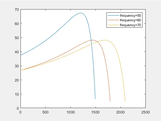
RESULT:-here we see xlabel is RPM and ylabel as Torque developed in a motor,with low frequency we experience high torque and low RPM ,where as with high frequency we experience high speed and low torque.
Learning Outcome:-
- Learn the Induction Motor Characteristics.
- Learn the Similarities of operation of induction motor to the clutch.
- Learn the steady-state condition of the motor.