Week-7 Challenge: DC Motor Control
AIM:- To Understand the DC Motor Characteristics & Control.
Objective:-To understand the BIT H-bridge model & how to control the speed.
To Understand the difference between DC7 & H-bridge models.
To understand the effect on the EV model using DC7 block, doing the modification.
#Ques 1- Run MATLAB demo 'Speed control of a DC motor using BJT H-bridgd Modify the model such that the Armature current doesn't shoot up when the motor changes direction from forward to reverse.
Introduction:- Now the day speed of motors plays an important role, not only for manufactures point and in addition to system stability point. The electric drive systems applied in industrial applications are gradually more required to get higher performance and requirements of reliability. The DC motor is an attractive part of equipment; in many applications of industrial requiring variable speed and load characteristics due to its ease of controllability.
DC MOTOR CONTROLLING USING H-BRIDGE:-
A DC motor can be controlled in different ways, basic the simplest way is being the ON-OFF switch, which allows the motor to control only at the maximum speed of rotation in one direction (switch ON) or stop (switch OFF). This ON-OFF control can be applied with a switch like a MOSFET, an electromechanical switch, or a BJT transistor, rest consider the DC motor is an inductive load. ON-OFF switching type of control allows speed control of the motor using pulse width modulation techniques, however, does not have the capacity to run the motor in both directions.
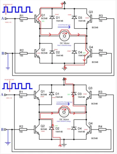
H-Bridge Control H-Bridge is one of the most important parts of the DC motor control circuit. It is a device that enables you to change the direction of the motor spin by altering the direction of current flow in the motor. When the motor is running in the opposite direction, it is essential to reverse the polarity of the current flowing in the motor using a circuit called an H-bridge. H-bridge consists of four controlled switches connected illustrate in Figure below. The key fact to note is that there are four switching elements within the bridge. These four elements are often called, high side left, high side right, low side right, and low side left (in clockwise order).
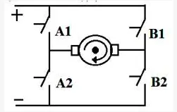
The figure is a Basic circuit diagram of H-Bridge Operating switches A2 and B1 when providing current flow through the motor in one direction, whereas operating switches Al and B2 provide current flow in the opposite direction. The arrangement with both A or B transistors turned on must be avoided. The bridge has a short circuit current on one side that could create serious damage to the bridge itself or the provided circuit. Solution
- Modifying the 'Speed control of a DC motor using BJT H-bridge' model such that the Armature current doesn't shoot up when the motor changes direction from forward to reverse
- Here I am setting up Technicians for the modeling of power components and to utilize computer simulation using the method, H-bridge for conducting control and transient.
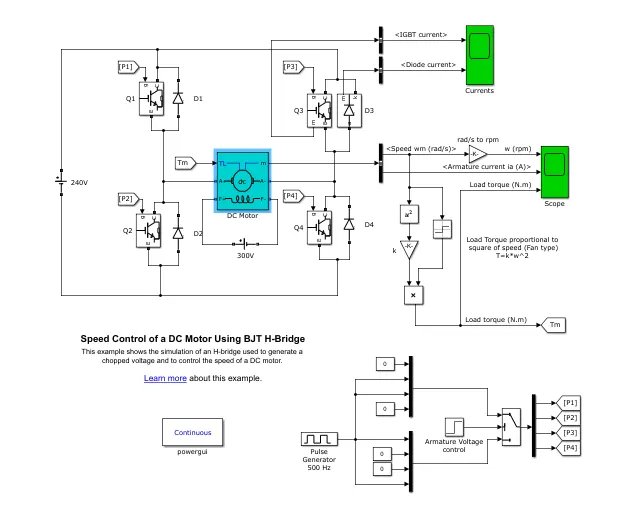
- The above Model is DC Motor using the BJT circuit, is working on the H-Bridge principle.
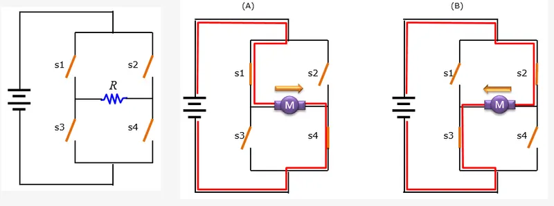
• The device is simply a circuit that has 4 switches connected in a series loop and a motor that is connected across the series, which forms an "H-Shaped" circuit, hence the name H-Bridge
• By putting the four switches on/off in a specific combination, you can change the direction of the current flowing through Motor M.
• In (A), the switch s1(Top Left) and s4(Right Bottom) are closed (ON), and s2(Top Right) and s3(Left Bottom) is Open (OFF). In this case, the electrical current flows along the path indicated by the Red-line, the direction is 'Left to Right
• In (B), the switch s2(Top Right) and s3(Left Bottom) is closed (ON), and s2(Top Right) and s4(Right Bottom) are Open (OFF). In this case, the electrical current flows along the path, you would notice the direction is 'Right to Left'.
• The direction of the current flow really matters because the direction of the current determines the direction of the motor spin. If the DC motor is connected to the wheels of a car, the direction of the current will determine the direction of car movement (moving forward or moving backward)
• The S1 & S2 combination is not run simultaneously as this will result in short-circuiting.
The DC Motor Model simulates to rotate the motor in one direction for the first half-cycle and in another direction for the next half-cycle.
• It consists of 2 PNP and 2 NPN connected along with a diode.
• Input current is controlled or switched by using the Pulse Generator, ON-OFF switching type of control allows speed control of the motor using pulse width modulation techniques.
• The cycle run for 1 second.
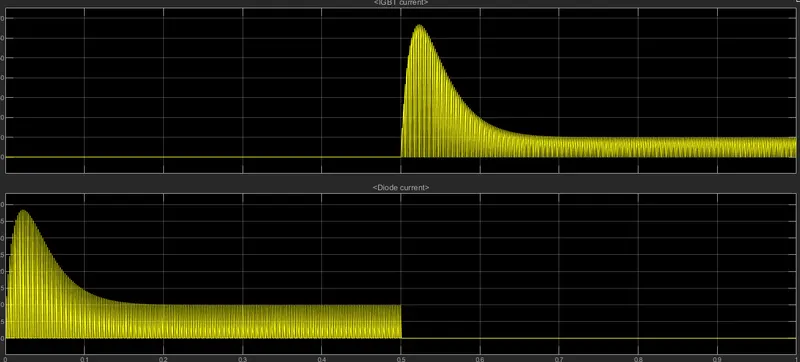
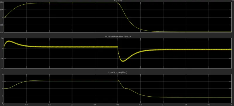
• From the Graph, it is shown that there is an armature current shoot up is happening. When the polarities changed back EMF generates due to which this shoot up is happening.
• This shut up depends on the amount of back emf generated.
• This back emf is reduced by giving some delay time, this time will reduce the current to 0 which reduces back emf and no shoot up will occur.
As per the requirement, we have to modify the model and reduced the shut up.
• ON-OFF switching type of control allows speed control of the motor using pulse width modulation techniques.
• This back emf is reduced by the ON-OFF switching type of control faster.
• This is done by decreasing the Pulse width in Pulse Generator Block.
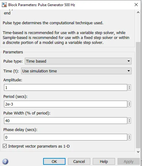
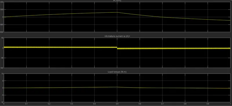
• In this case, if we set pulse width at 50%, it means 50% period gate pulse is generated and 50% period gate puke is not generated.
• So to fulfil our requirement, I reduced the puke width from 75 to 40 in order to reduce the shoot
• However, it is not a standard practice to do, as it can be seen from the plot when the puke width is changed to 40 the torque and speed also reducing to reaching close to 0, which is not a good practice.
• Here I did this just for study purpose as it affects the Torque and speed, and reduce it drastically.
• Doing so we get the desired output for Armature Current.
#Ques 2- Refer to the help section of The Four-Quadrant Chopper DC Drive (DC7) block Compare it with the H-bridge model.
Four-Quadrant Chopper- Chopper is a basically static power electronics device that converts fixed DC voltage/power to variable DC voltage or power. It is nothing but a high-speed switch that connects and disconnects the load from the source at a high rate to get variable or chopped voltage at the output.
H-bridge model- An H-bridge is an electronic circuit that switches the polarity of a voltage applied to a load. These circuits are often used to allow DC motors to run forwards or backward.
Four-Quadrant Chopper DC Drive (DC7) block
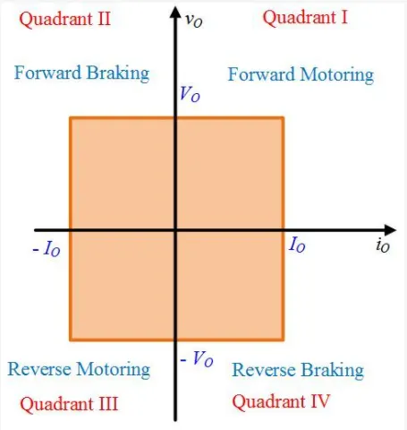
1. A Four-Quadrant Chopper DC Drive (DC7) block is a chopper that can be operated in all four quadrants.
2. In a four-quadrant chopper, Regenerative Braking can be done
3. The power can flow either from source to load or load to source in it
4. DC chopper device has the advantages of high efficiency, flexibility in control, lightweight, small size, quick response, and regeneration down to very low speed. 5. The Four Quadrant chopper drives it, uses ramps to reduce the shoot up current, and provide stability. 6. The main Advantage of Four-Quadrant Chopper DC Drive is, it can operate in all four quadrants
- First Quadrant- Forward Motoring
- Second Quadrant- Forward Braking
- Third Quadrant- Reverse Motoring
- Fourth Quadrant- Reverse Braking
H-bridge model
1. In the case of H-bridge, the Bipolar Junction Transistor (BJT) operates as an IGBT when used for power switching applications.
2. Regenerative braking is not possible.
3. In half-bridge the output voltage waveforms are square, quasi square, or PWM
4. An H Bridge inverter will not create a pure sine wave, but rather a 'modified square wave. That is to say, a square wave with some off time between the positive and negative transitions. This is just about good enough for powering resistive loads or switched-mode power supplies but is not suitable for inductive loads or other devices that require as pure a sine wave as possible.
5. In H-bridge the current shoot-up is high due to switching losses, it can be reduced by changing the pulse width, but it is not. 6. H-bridge can operate only in two modes, - Forward and Reverse
#Ques 3- Make a suitable EV model using DC7 block and make a result report.
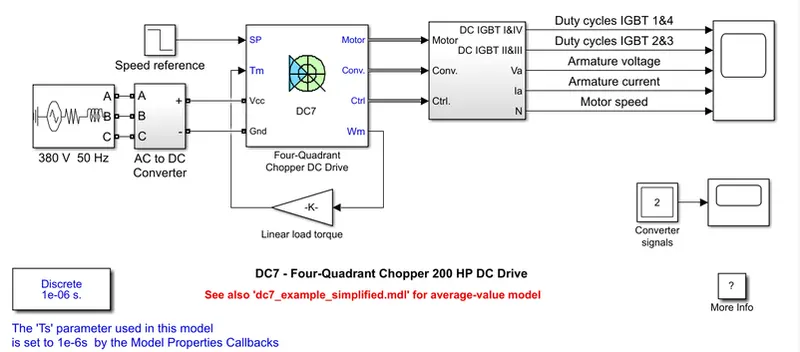
Procedure -
In accordance to make it suitable EV model,
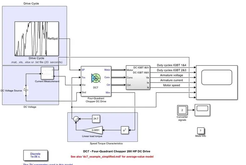
- We know the vehicle speed-torque characteristics, are given by the below equation
Tv = 24.7 + (0.0051)w^2
- We will put this equation to provide the input Torque, instead of linear load torque, so as to use the actual vehicle speed-torque characteristics.
- The energy source of an EV is a battery, so I use a DC voltage source from Simulink Library
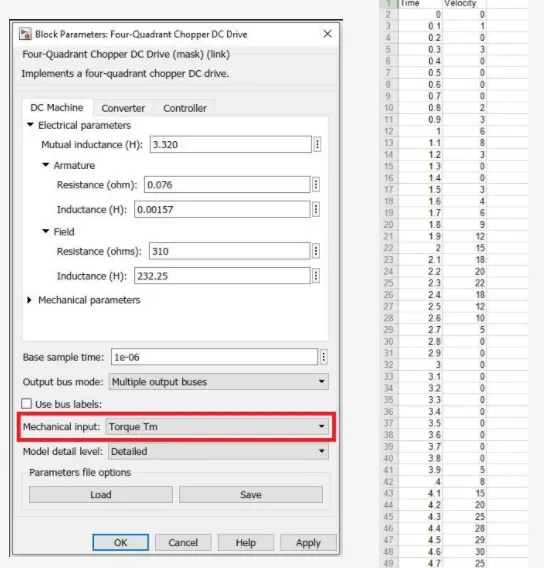
- In according to create an actual environment for the vehicle, I create a Drive cycle in Excel and put it as an input to the vehicle using Drive Cycle Block
- In order to make a suitable EV model, we edit the DC7 block parameter to give the torque feedback input. Modified Model-
result:-
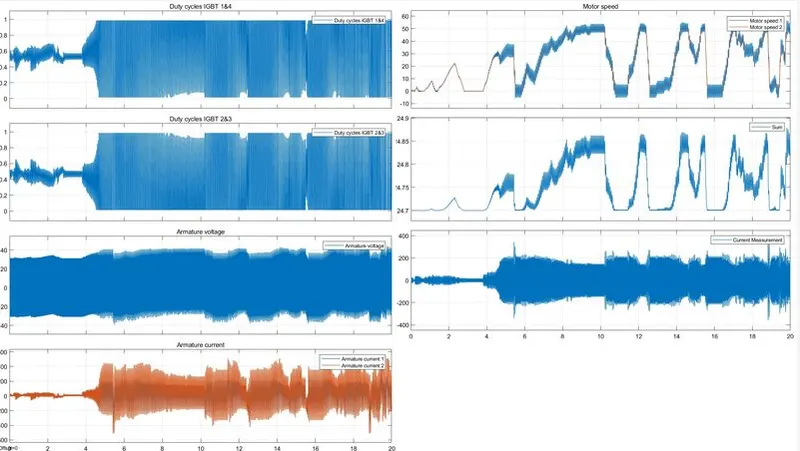
zooming in:-
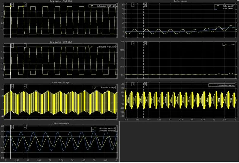
- From the Graph, we take one cycle for study, in this set between points 1 & 2,
- It is seen that when the signal across the IGBT 1 and 4 is Low, the signal across IGBT 2 and 3 is High or can say if the signal across the IGBT 1 and 4 are increasing than the signal across IGBT 2 and 3 is decreasing during acceleration.
- Operating Voltage remains constant through the cycle and operates the motot.
- It can be seen with the increase in motor speed, the current requirement is also increased, and when motor speed decreases the current drawn from the battery also decreases.
- During the brakes the regenerative braking happens, due to which Armature current goes negative.
Learning Outcome:-
- Learn the BJT H-bridge model and its operations
- Learn the difference between DC7 & H-bridge models.
- Understand the effect on the EV model using the block.