Project-1: Powertrain for aircraft in runways
1. TOTAL WEIGHT OF VARIOUS TYPES OF AIRCRAFT:
An aircraft's gross weight is limited by several weight restrictions in order to avoid overloading its structure or to avoid unacceptable performance or handling qualities while in operation.
Aircraft gross weight limits are established during an aircraft's design and certification period and are laid down in the aircraft's type certificate and manufacturer specification documents.
The absolute maximum weight capabilities of a given aircraft are referred to as the structural weight limits. The structural weight limits are based on aircraft maximum structural capability and define the envelope for the CG charts (both maximum weight and CG limits).
An aircraft's structural weight capability is typically a function of when the aircraft was manufactured, and in some cases, old aircraft can have their structural weight capability increased by structural modifications.
Maximum design taxi weight (MDTW)
The maximum design taxi weight (also known as the maximum design ramp weight (MDRW)) is the maximum weight certificated for aircraft manoeuvring on the ground (taxiing or towing) as limited by aircraft strength and airworthiness requirements.
Maximum design takeoff weight (MDTOW)
Is the maximum certificated design weight when the brakes are released for takeoff and is the greatest weight for which compliance with the relevant structural and engineering requirements has been demonstrated by the manufacturer.
Maximum design landing weight (MDLW)
The maximum certificated design weight at which the aircraft meets the appropriate landing certification requirements. It generally depends on the landing gear strength or the landing impact loads on certain parts of the wing structure.
The MDLW must not exceed the MDTOW.
The maximum landing weight is typically designed for 10 feet per second (600 feet per minute) sink rate at touch down with no structural damage.
Maximum design zero-fuel weight (MDZFW)
The maximum certificated design weight of the aircraft less all usable fuel and other specified usable agents (engine injection fluid, and other consumable propulsion agents). It is the maximum weight permitted before usable fuel and other specified usable fluids are loaded in specified sections of the airplane. The MDZFW is limited by strength and airworthiness requirements. At this weight, the subsequent addition of fuel will not result in the aircraft design strength being exceeded. The weight difference between the MDTOW and the MDZFW may be utilised only for the addition of fuel.
Minimum flight weight (MFW)
Minimum certificated weight for flight as limited by aircraft strength and airworthiness requirements.
|
Type |
MTOW [kg] |
MLW [tonnes] |
TOR [m] |
LR [m] |
||
|
640,000 |
591.7 |
3500 |
Heavy |
Super |
||
|
589,670 |
3660 |
Heavy |
Super |
|||
|
575,000 |
394 |
3100 |
1930 |
Super |
Super |
|
|
447,700 |
346.091 |
3100 |
1800 |
Heavy |
Heavy |
|
|
443,613 |
306.175 |
3100 |
Heavy |
Heavy |
||
|
412,770 |
295.742 |
3090 |
Heavy |
Heavy |
||
|
Antonov An-124-100M |
405,060 |
330 |
2520 |
900 |
Heavy |
Heavy |
|
396,900 |
295.742 |
3018 |
2179 |
Heavy |
Heavy |
|
|
381,000 |
288.417 |
2530 |
1494 |
Heavy |
Heavy |
|
|
377,840 |
285.700 |
3338 |
2109 |
Heavy |
Heavy |
|
|
377,840 |
260.320 |
3222 |
1905 |
Heavy |
Heavy |
|
|
371,950 |
240 |
3050 |
2010 |
Heavy |
Heavy |
|
|
367,400 |
256 |
3100 |
2100 |
Heavy |
Heavy |
|
|
347,800 |
260.816 |
2830 |
Heavy |
Heavy |
||
|
352,000 |
251.5 |
3100 |
Heavy |
Heavy |
||
|
351,800 |
251.29 |
3100 |
Heavy |
Heavy |
||
|
347,450 |
223.168 |
3000 |
Heavy |
Heavy |
||
|
340,200 |
265.300 |
Heavy |
Heavy |
|||
|
308,000 |
233.5 |
Heavy |
Heavy |
|||
|
299,370 |
237.683 |
3380 |
Heavy |
Heavy |
||
|
297,550 |
213.00 |
3380 |
1550 |
Heavy |
Heavy |
|
|
276,700 |
190 |
3000 |
1926 |
Heavy |
Heavy |
|
|
273,300 |
185 |
2990 |
1890 |
Heavy |
Heavy |
|
|
270,000 |
175 |
2670 |
1860 |
Heavy |
Heavy |
|
|
270,000 |
195.04 |
3115 |
2118 |
Heavy |
Heavy |
|
|
256,280 |
183 |
2990 |
1890 |
Heavy |
Heavy |
|
|
254,000 |
192.777 |
2900 |
Heavy |
Heavy |
||
|
254,000 |
201.849 |
Heavy |
Heavy |
|||
|
253,500 |
181 |
2990 |
Heavy |
Heavy |
||
|
250,000 |
175 |
2600 |
1980 |
Heavy |
Heavy |
|
|
242,000 |
185 |
2500 |
1750 |
Heavy |
Heavy |
|
|
242,000 |
180 |
2220 |
1750 |
Heavy |
Heavy |
|
|
231,300 |
166.92 |
2636 |
Heavy |
Heavy |
||
|
228,000 |
172.365 |
3300 |
1695 |
Heavy |
Heavy |
|
|
211,400 |
Heavy |
Heavy |
||||
|
208,000 |
175 |
Heavy |
Heavy |
|||
|
204,000 |
158.758 |
3414 |
Heavy |
Heavy |
||
|
192,000 |
140 |
2385 |
1555 |
Heavy |
Heavy |
|
|
187,000 |
136.08 |
2713 |
1676 |
Heavy |
Heavy |
|
|
185,000 |
111.1 |
3440 |
2220 |
Heavy |
Heavy |
|
|
163,000 |
138 |
2324 |
1536 |
Heavy |
Heavy |
|
|
159,000 |
136.078 |
2713 |
1676 |
Heavy |
Heavy |
|
|
157,000 |
124 |
2290 |
1490 |
Heavy |
Heavy |
|
|
152,000 |
151.9 |
Heavy |
Heavy |
|||
|
151,000 |
97.5 |
Heavy |
Heavy |
|||
|
151,000 |
112.1 |
Heavy |
Heavy |
|||
|
147,000 |
Heavy |
Heavy |
||||
|
142,000 |
123 |
1860 |
1480 |
Heavy |
Heavy |
|
|
141,000 |
122 |
980 |
770 |
Heavy |
Heavy |
|
|
140,000 |
Heavy |
Heavy |
||||
|
125,000 |
Medium |
Large |
||||
|
124,000 |
101.6 |
2550 |
1750 |
Medium |
Large |
|
|
117,000 |
86.3 |
Medium |
Large |
|||
|
116,000 |
89.9 |
2347 |
1555 |
Medium |
Large |
|
|
106,000 |
79.5 |
Medium |
Large |
|||
|
104,000 |
79.5 |
Medium |
Large |
|||
|
104,000 |
80 |
Medium |
Large |
|||
|
104,000 |
87.5 |
2250 |
Medium |
Large |
||
|
87,500 |
Medium |
Large |
||||
|
85,000 |
66.36 |
2500 |
1704 |
Medium |
Large |
|
|
85,000 |
71.35 |
2804 |
1829 |
Medium |
Large |
|
|
84,000 |
70.1 |
Medium |
Large |
|||
|
Airbus A321-100[18] |
83,000 |
77.8 |
2200 |
1540 |
Medium |
Large |
|
79,000 |
65.32 |
2308 |
1634 |
Medium |
Large |
|
|
78,000 |
68.1 |
Medium |
Large |
|||
|
73,000 |
63.28 |
Medium |
Large |
|||
|
72,500 |
62.4 |
Medium |
Large |
|||
|
72,500 |
62.4 |
Medium |
Large |
|||
|
71,000 |
64.41 |
2165 |
1520 |
Medium |
Large |
|
|
70,700 |
Medium |
Large |
||||
|
70,000 |
58.06 |
1921 |
1415 |
Medium |
Large |
|
|
Airbus A320-100[18] |
68,000 |
66 |
1955 |
1490 |
Medium |
Large |
|
68,000 |
54.9 |
2540 |
1540 |
Medium |
Large |
|
|
68,000 |
Medium |
Large |
||||
|
67,000 |
Medium |
Large |
||||
|
66,000 |
54.66 |
1796 |
1340 |
Medium |
Large |
|
|
65,000 |
57.61 |
1890 |
1494 |
Medium |
Large |
|
|
65,000 |
Medium |
Large |
||||
|
64,000 |
62.5 |
1850 |
1470 |
Medium |
Large |
|
|
63,000 |
51.7 |
1939 |
1396 |
Medium |
Large |
|
|
60,000 |
49.9 |
1832 |
1360 |
Medium |
Large |
|
|
59,000 |
50.80 |
1463 |
1356 |
Medium |
Large |
|
|
59,000 |
57.5 |
1375 |
1340 |
Medium |
Large |
|
|
55,000 |
47.174 |
1950 |
Medium |
Large |
||
|
55,000 |
Medium |
Large |
||||
|
54,000 |
Medium |
Large |
||||
|
50,000 |
46.265 |
1950 |
Medium |
Large |
||
|
50,000 |
Medium |
Large |
||||
|
48,600 |
Medium |
Large |
||||
|
48,500 |
Medium |
Large |
||||
|
48,000 |
43 |
2056 |
1323 |
Medium |
Large |
|
|
46,000 |
Medium |
Large |
||||
|
46,000 |
39.95 |
1621 |
1350 |
Medium |
Large |
|
|
44,000 |
Medium |
Large |
||||
|
42,000 |
36.74 |
Medium |
Large |
|||
|
39,000 |
Medium |
Large |
||||
|
37,500 |
32.8 |
2244 |
1304 |
Medium |
Large |
|
|
36,500 |
33.345 |
1778 |
1596 |
Medium |
Large |
|
|
36,000 |
32.8 |
1644 |
1274 |
Medium |
Large |
|
|
33,000 |
30.39 |
1564 |
1478 |
Medium |
Large |
|
|
33,000 |
Medium |
Large |
||||
|
30,400 |
Medium |
Large |
||||
|
28,000 |
28.01 |
1219 |
1295 |
Medium |
Large |
|
|
23,000 |
21.319 |
1918 |
1479 |
Medium |
Large |
|
|
22,800 |
22.35 |
1333 |
914 |
Medium |
Large |
|
|
22,800 |
21.5 |
1300 |
Medium |
Large |
||
|
22,000 |
19.3 |
2270 |
1380 |
Medium |
Large |
|
|
18,600 |
18.3 |
1165 |
1126 |
Medium |
Small |
|
|
13,150 |
12.930 |
1300 |
1030 |
Medium |
Small |
|
|
11,500 |
11.25 |
1560 |
1380 |
Medium |
Small |
|
|
10,890 |
10.570 |
1493 |
826 |
Medium |
Small |
|
|
9,752 |
8.709 |
1353 |
811 |
Medium |
Small |
|
|
8,300 |
7.665 |
893 |
724 |
Medium |
Small |
|
|
8,150 |
7.65 |
956 |
677 |
Medium |
Small |
|
|
7,765 |
7.605 |
1036 |
853 |
Medium |
Small |
|
|
7,761 |
7.103 |
1039 |
896 |
Medium |
Small |
|
|
7,000 |
Medium |
Small |
||||
|
4,800 |
4.43 |
975 |
741 |
Light |
Small |
2. yes there is an difference between ground speed and air speed:
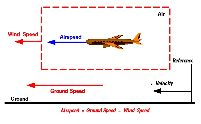
Wind Speed
For a reference point picked on the ground, the air moves relative to the reference point at the wind speed. Notice that the wind speed is a vector quantity and has both a magnitude and a direction. Direction is important. A 20 mph wind from the west is different from a 20 mph wind from the east. The wind has components in all three primary directions (north-south, east-west, and up-down). In this figure, we are considering only velocities along the aircraft's flight path. A positive velocity is defined to be in the direction of the aircraft's motion. We are neglecting cross winds, which occur perpendicular to the flight path but parallel to the ground, and updrafts and downdrafts, which occur perpendicular to the ground.
Ground Speed
For a reference point picked on the ground, the aircraft moves relative to the reference point at the ground speed. Ground speed is also a vector quantity so a comparison of the ground speed to the wind speed must be done according to rules for vector comparisons.
Airspeed
The important quantity in the generation of lift is the relative velocity between the object and the air, which is called the airspeed. Airspeed cannot be directly measured from a ground position, but must be computed from the ground speed and the wind speed. Airspeed is the vector difference between the ground speed and the wind speed.
Airspeed = Ground Speed - Wind Speed
On a perfectly still day, the airspeed is equal to the ground speed. But if the wind is blowing in the same direction that the aircraft is moving, the airspeed will be less than the ground speed.
Examples
Suppose we had an airplane that could take off on a windless day at 100 mph (liftoff airspeed is 100 mph). We are at an airport with an east-west runway that is 1 mile long. The wind is blowing 20 mph towards the west and the airplane takes off going east. The wind is blowing towards the aircraft which we call a headwind. Since we have defined a positive velocity to be in the direction of the aircraft's motion, a headwind is a negative velocity. While the plane is sitting still on the runway, it has a ground speed of 0 and an airspeed of 20 mph:
Airspeed = Ground Speed (0) - Wind Speed (-20) = 20 mph
The airplane starts its take off roll and has a constant acceleration a. From Newton's second law of motion, the ground speed V at any time t is:
V = a * t
3)Why is it not recommended to use aircraft engine power to move it on the ground at Airport?
Taxiing (rarely spelled taxying) is the movement of an aircraft on the ground, under its own power, in contrast to towing or pushbackk where the aircraft is moved by a tug. The aircraft usually moves on wheels, but the term also includes aircraft with skis or floats (for water-based travel).
Engine power is used all the time to move aircraft on the ground. engine power is used all the time in the ramp. They do get pushed back because only aircraft with engines on the tail can power-back due to FOD. Sometimes, if ifs a tight area, a tug will be used
Jet blast effect while taxiing( single ENGINE TAXIING) There is also a blast effect during taxiing, although it is not as powerful as when the aircraft is taking off. Unlike taking off or landing, taxiing often occurs in the vicinity of passengers, employees and unsecured objects. This can lead to hazardous situations if the blast is too powerful. The risk therefore has to be minimised while starting up the engines and taxiing.
To cut a long story short, to achieve this, most airlines set the maximum thrust percentage at 40% of total capacity per engine during taxiing. Airports are designed to be a safe places to work and visit, but this depends on only 40% of the engine's thrust being used during taxiing. An aircraft that taxies using both engines can easily keep below that limit. But if you were to turn off one engine, the remaining engine would need to use much more power.
Particularly when the aircraft moves away from a standing position, the so-called breakaway thrust would need to exceed the safe level of 40%. So whether or not Single-Engine Taxiing is feasible depends on how difficult it is to get the aircraft moving. If the aircraft is on a gradient, and especially if the aircraft is relatively heavy, there is a higher chance that too much power would be required. This is the reason why Single-Engine Taxiing is used more fuel.
4) How an aircraft is pushed to runway when its ready to take off?
In aviation, pushback is an airport procedure during which an aircraft is pushed backwards away from an airport gate by external power. Pushbacks are carried out by special, low-profile vehicles called pushback tractors or tugs.
Although many aircraft are capable of moving themselves backwards on the ground using reverse thrust (a procedure referred to as a powerback), the resulting jet blast or prop wash might cause damage to the terminal building or equipment. Engines close to the ground may also blow sand and debris forward and then suck them into the engine, causing damage to the engine. A pushback is therefore the preferred method to move the aircraft away from the gate.
Pushbacks at busy aerodromes are usually subject to ground control clearance to facilitate ground movement on taxiways. Once clearance is obtained, the pilot will communicate with the tractor driver (or a ground handler walking alongside the aircraft in some cases) to start the pushback. To communicate, a headset may be connected near the nose gear.
Since the pilots cannot see what is behind the aircraft, steering is done by the pushback tractor driver and not by the pilots. Depending on the aircraft type and airline procedure, a bypass pin may be temporarily installed into the nose gear to disconnect it from the aircraft's normal steering mechanism.
Once the pushback is completed, the towbar is disconnected, and any bypass pin removed. The ground handler will show the bypass pin to the pilots to make it clear that it has been removed. The pushback is then complete, and the aircraft can taxi forward under its own power
Moving light aircraft
Very small airplanes may be moved by human power alone. The airplane may be pushed or pulled by landing gear or wing struts since they're known to be strong enough to drag the airplane through the air. To allow for turns, a person may either pick up or push down on the tail to raise either the nose wheel or tail wheel off the ground, then rotate the airplane by hand. A less cumbersome method involves attaching a short tow bar to either the nose wheel or tail wheel, which provides a solid handhold and leverage to steer with, as well as eliminates the danger of handling the propeller. These tow bars are usually a lightweight aluminum alloy construction which allows them to be carried on board the airplane. Other small tow bars have a powered wheel to help move the airplane, with power sources as diverse as lawnmower engines or battery-operated electric drills. However, powered tow bars are usually too large and heavy to be practically carried on small airplanes.
Tractors and towbars
Large aircraft cannot be moved by hand and must have a tractor or tug. Pushback tractors use a low profile design to fit under the aircraft nose. For sufficient traction the tractor must be heavy, and most models can have extra ballast added. A typical tractor for large aircraft weighs up to 54 tonnes (59.5 short tons; 53.1 long tons; 119,000 pounds) and has a drawbar pull of 334 kN (75,000 lbf). Often the driver's cabin can be raised for increased visibility when reversing and lowered to fit under aircraft. There are two types of pushback tractors: conventional and towbarless (TBL).
Conventional tugs use a tow bar to connect the tug to the nose landing gear of the aircraft. The tow bar is fixed laterally at the nose landing gear, but may move slightly vertically for height adjustment. At the end that attaches to the tug, the tow bar may pivot freely laterally and vertically. In this manner the tow bar acts as a large lever to rotate the nose landing gear. Each aircraft type has a unique tow fitting so the towbar also acts as an adapter between the standard-sized tow pin on the tug and the type-specific fitting on the aircraft's landing gear. The tow bar must be long enough to place the tug far away enough to avoid hitting the aircraft and to provide sufficient leverage to facilitate turns. On heavy tow bars for large aircraft the towbar rides on its own wheels when not connected to an aircraft. The wheels are attached to a hydraulic jacking mechanism which can lift the towbar to the correct height to mate to both the airplane and the tug, and once this is accomplished the same mechanism is used in reverse to raise the tow bar wheels from the ground during the pushback process. The tow bar can be connected at the front or the rear of the tractor, depending on whether the aircraft will be pushed or pulled. The towbar has a shear pin which prevents the aircraft from being mishandled by the tug; when overstressed the shear pin will snap, disconnecting the bar from the nose gear to prevent damage to the aircraft and tug.
Towbarless (TBL) tractors do not use a towbar; they scoop up the nose landing gear and lift it off the ground. This avoids the time penalty of connecting/disconnecting a towbar, and entirely removes the cost/complexity of maintaining towbars on the ramp. The tug itself does not need to be particularly massive - the aircraft's nosewheel weight provides the necessary downward force. Lastly, a TBL tug is much shorter (compared to a tug+towbar system) and has one only a single pivot point instead of one at either end of the towbar, so it has much simpler and precise control of the aircraft. This is very useful in general aviation settings with a wider variety of aircraft in more confined spaces than their airline counterparts.
Manufacturers of electric TBL tugs offer models capable of moving any aircraft from the smallest single-engine type to narrow-body airliners, military cargo and airline-sized business jets. Just as specialized towbars are required for a wide range of aircraft, many TBL tugs use adapters which enable the movement of many unique aircraft. The majority of aircraft do not require adapters and can be moved without any special adjustments to the tug. This is in contrast to conventional tugs which often use so-called "universal" towbars which must be adjustable to suit many aircraft types. Electric TBL tugs are gaining popularity among general aviation operators and FBOs as an alternative to gas or diesel-powered conventional tugs. Being electric rather than internal combustion-powered, electric tugs are low-emission which is a major advantage for environmentally-conscious operators; this also enables the tug to be safely operated inside a closed hangar.
5)Learn about take off power, tyre design, rolling resistance, tyre pressure, brake forces when landing.
On take-off, in order to position the aircraft to a safe height away from terrain and obstacles (i.e. a flight path of maximum height and minimum ground distance desired), the engine thrust is set to a high ‘take-off power’ setting (although this is not necessarily full power) and the aircraft attitude is pitched up to maintain a specific speed (usually in the region of V2 + 15kts). Once the ‘safe height’ is reached the engine thrust can therefore be reduced to a more appropriate (i.e. efficient) setting and the aircraft flight path can be changed to a more appropriate (i.e. efficient) flight path.
In order to achieve that described above and also to provide minimum noise disturbance to the area surrounding the airport, regulatory procedures require aircraft to fly one of the two profiles given below during every departure. The aerodrome briefing pages will state which one of the two profiles is to be flown at each particular airport:
- At 1,500ft aal reduce thrust to climb power and accelerate the aircraft towards 250 knots, retracting flaps and slats.
- At 1,500ft aal reduce thrust to climb power maintaining V2 + 15kts. At 3,000ft accelerate the aircraft.
Operator’s SOPs must therefore enable the above procedures to be flown and, as such, controllers will witness flight crews performing certain actions and verbal SOP callouts during the initial climb in order to accomplish this. Aircraft that have highly automated systems will perform the thrust reduction and acceleration manoeuvre with minimal input from the flight crew. Note that the flight crew must input the required data into the FMS during the pre-flight procedure to enable such aircraft to accomplish this. In such aircraft it may be the case that the only physical action required by the flight crew is to move the flap lever, the remainder of the actions are of a monitoring nature to ensure that the correct Flight Mode Annunciator (FMA) modes engage and that the aircraft physically performs the manoeuvre correctly. In less automated aircraft it will require an increased amount of button pushing, knob turning and verbal calls to perform the thrust reduction and acceleration manoeuvre. During the initial climb, at the heights stated above, the thrust reduction and acceleration procedure therefore gives rise to issues regarding increased workload in the flight deck.
Why are tyres important in Aircraft?
When it comes to safety, tyres are one of the most important components of aircraft. They help to absorb the shock of landing and provide cushioning. It also provides the necessary traction for braking and stopping of an aircraft.
An aircraft tyre is designed to withstand extremely heavy loads while landing, take off, taxing, and parking. The number of wheels required for aircraft increases with the weight of the aircraft, as the weight of the aeroplane needs to be distributed more evenly.
Design and Construction of Aircraft tyre
Carcass plies are used to form the tire. They are sometimes called casing plies. An aircraft tyre is constructed for the purpose it serves.
- They support the weight of an aircraft while it is on the ground.
- It also provides the necessary traction for braking and stopping of an aeroplane.
- Tyre also helps to absorb the shock of landing and provide cushioning the roughness of takeoff, roll-out, and taxi operations.
Unlike an automobile or truck tyre, it does not have to carry a load for a long period of continuous operation. However, an aircraft tyre absorbs the high impact loads of landing, and also it’s operating at high speeds for a short time when required.
Let’s go through some technical aspects of the tyre.
Retreading – Retreading is methods of restoring a worn tyre by renewing the tread area or by renewing the tread area plus one or both sidewalls. Repairs are included in the tyre retreading process.
Load Rating – Load rating is the maximum permissible load at a specified inflation pressure.
Ply Rating – Ply Rating is used to identify the maximum recommended load rating and inflation pressure for a specified tyre. It is an index of tyre strength.
Speed Rating – The speed rating is the maximum takeoff speed to which the tyre has been tested.
Skid Depth – Skid depth is the distance between the tread surface and the deepest groove as measured in the mould.
Aircraft tyres must have an approved speed and load rating and have sufficient clearance when retracted through landing gear to allow for tyre growth. Tyre growth is the increase in the size of the tyre due to centrifugal forces at high speed.
Aircraft tyres may be Tube-type or Tubeless
Tubeless tyres are more advantageous over tube-type. There is no longer the use of tube-type tyre in recent aviation. Nowadays all airliners are using tubeless tyres. Tubeless that are meant to be used without a tube has the word TUBELESS on the sidewall of the tyre.
Aircraft tyres may be Radial or Bias
Almost all airliners are using Radial tyre. Bias is an older design, and it’s mainly used for road vehicles. Radial tyres have the word RADIAL on the sidewall. Radial tires are more expensive than bias-ply tyres. Radial tires are in demand because of their lower life cycle cost and long term value.
Further Read: Aircraft Radial vs Bias Tyre
Are aviation tyres are conductive?
Yes, Today’s tyres are conductive. Aircraft tyres are manufactured with tread rubber with conducting compounds to permit earthing of static charges.
In early days when tyres were not sufficiently conductive, aircraft used to have a conductive strip hanging down from the axle of the landing gear. Upon landing, this strip would be the first part of the aircraft to touch the earth. This discharges any static electricity accumulated on the outer surfaces of the aircraft. Now you don’t see them anymore.
What is the purpose of Chines in aviation tyre
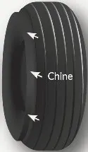
Chines are also called deflectors. Chine tyre used on the nose wheel of aircraft, specially fuselage-mounted jet engines. It diverts runway water away from the engine inlets.
Chines are circumferential protrusions that are moulded into the sidewall of nose tyres that deflect water sideways to help reduce excess water ingestion into the engines. Tyres may have chines on one or both sides, depending on the number of nose tyres on the aircraft.
Aircraft Tyre Standards
Each tyre manufacturer produces their own designs of the tyre with different tread patterns, wear patterns, wear limits etc, and in some cases, different names for the same part of the tyre. But all tyres must meet the approved standards before being accepted by the FAA or CAA.
All commercial aircraft tyres approved under FAA Requirement Technical Standard Order (TSO) C62. A TSO is a minimum performance standard for specified materials, parts, and appliances used on civil aircraft.
Rolling resistance
Rolling resistance, sometimes called rolling friction or rolling drag, is the force resisting the motion when a body (such as a ball, tire, or wheel) rolls on a surface. It is mainly caused by non-elastic effects; that is, not all the energy needed for deformation (or movement) of the wheel, roadbed, etc., is recovered when the pressure is removed. Two forms of this are hysteresis losses (see below), and permanent (plastic) deformation of the object or the surface (e.g. soil). Another cause of rolling resistance lies in the slippage between the wheel and the surface, which dissipates energy. Note that only the last of these effects involves friction, therefore the name "rolling friction" is to an extent a misnomer.
In analogy with sliding friction, rolling resistance is often expressed as a coefficient times the normal force. This coefficient of rolling resistance is generally much smaller than the coefficient of sliding friction.[1]
Any coasting wheeled vehicle will gradually slow down due to rolling resistance including that of the bearings, but a train car with steel wheels running on steel rails will roll farther than a bus of the same mass with rubber tires running on tarmac. Factors that contribute to rolling resistance are the (amount of) deformation of the wheels, the deformation of the roadbed surface, and movement below the surface. Additional contributing factors include wheel diameter,[2] load on wheel, surface adhesion, sliding, and relative micro-sliding between the surfaces of contact. The losses due to hysteresis also depend strongly on the material properties of the wheel or tire and the surface. For example, a rubber tire will have higher rolling resistance on a paved road than a steel railroad wheel on a steel rail. Also, sand on the ground will give more rolling resistance than concrete. Sole rolling resistance factor is not dependent on speed.
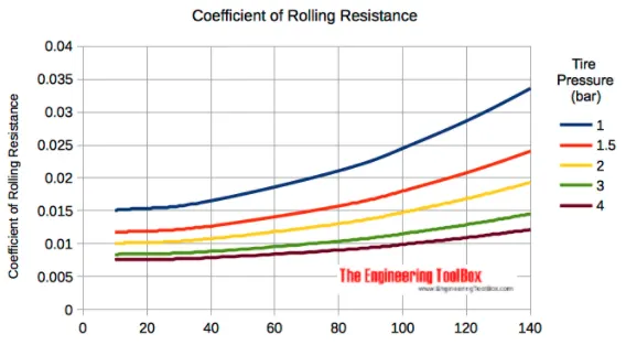
tyre pressure of aircraft
An aircraft tire or tyre is designed to withstand extremely heavy loads for short durations.[1] The number of tires required for aircraft increases with the weight of the aircraft, as the weight of the airplane needs to be distributed more evenly. Aircraft tire tread patterns are designed to facilitate stability in high crosswind conditions, to channel water away to prevent hydroplaning, and for braking effect.
Aircraft tires also include fusible plugs (which are assembled on the inside of the wheels), designed to melt at a certain temperature. Tires often overheat if maximum braking is applied during an aborted takeoff or an emergency landing. The fuses provide a safer failure mode that prevents tire explosions by deflating in a controlled manner, thus minimizing damage to aircraft and objects in the surrounding environment.
Each of the twelve Boeing 777-300ER main tires is inflated to 220 psi (15 bar; 1,500 kPa), weighs 120 kg (260 lb), has a diameter of 134 cm (53 in) and is changed every 300 cycles while the brakes are changed every 2000 cycles.[2] Each tire is worth about $5,000.[3] Aircraft tires generally operate at high pressures, up to 200 psi (14 bar; 1,400 kPa) for airliners, and even higher for business jets
List of aircraft braking systems
Aircraft braking systems include:
- Aircraft disc brakes in the landing gear, used to brake the wheels while touching the ground. These brakes are operated hydraulically or pneumatically. In most modern aircraft they are activated by the top section of the rudder pedals ("toe brakes"). In some older aircraft the bottom section is used instead ("heel brakes"). Levers are used in a few aircraft. Most aircraft are capable of differential braking.[1]
- Thrust reversers, that allow thrust from the engines to be used to slow the aircraft.
- Air brakes, dedicated flight control surfaces that work by increasing drag.
- Large drogue parachutes, used by several former and current military and civilian aircraft (examples include the American B-52 and the soviet Tu-134 and Tu-144) and in the Space Shuttle
6)With necessary assumptions, calculate the force and power required to push / pull an aircraft by a towing vehicle.
The force to move an airplane on an absolute flat runway with no wind at constant low speed is equal to the rolling resistance between the plane and the tarmac.
The rolling resistance for the air plane can be calculated as
Fr = c mr ag
where
Fr = rolling resistance (N, lbf)
c = rolling resistance coefficient
mr = rolling mass (kg, lbm)
ag = acceleration of gravity (9.81 m/s2)
Example - Force required to pull an airplane at constant low speed on tarmac
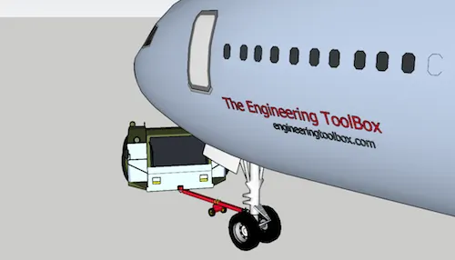
If the mass of a plane is 40000 kg and the rolling coefficient between the aircraft wheel and the tarmac is 0.02 - the force required to overcome the rolling resistance can be calculated as
Fr = 0.02 (40000 kg) (9.81 m/s2)
= 7848 N
This force can be delivered by a pulling truck or - as occasionally seen - by a number of pulling people. Enough weight for the pullers are required to create friction forces against the tarmac that equals the plane rolling resistance.
The friction force for the puller can be calculated to
Ff = μ W
= μ mf ag (2)
where
Ff = frictional force (N, lb)
μ = friction coefficient
W = weight (N, lbf)
mf = friction mass (kg)
v=9.72 m/s
power =F*v (velocity where truck pulls the airplane) power=7848*9.72=76.282 Kw
Study 7: Designing an electric powertrain with type of motor it's power rating and energy requirement to fulfill aircraft towing application. Estimating the duty cycle range to control the aircraft speed from zero to highest. Taking all required assumptions. Preparing a table of assumed parameters. Creating a block diagram of powertrain.
We know the power required is 8523.88 watt. Hence, the motor required to do this job should have power rating above 8523.88 watts or 11.5HP. Type of motor to use: DC brushless motor and AC motor are the two motors which can be used efficiently for propulsion of vehicles with the help of inverters and controllers.
However, AC motor can give high starting torque compared to DC. Also, there is a 12.5HP motor available which can quite perfectly meet our requirement as they produce high starting torque. We are moving the load with a speed not above 5kmph, and require high starting torque. Hence, AC motor of 12.5HP is suitable for our purpose.
Power Rating of the motor:

These are the motor with power rating above 8523.88watt. The average current at full load w.r.t. specific voltage supply is given in the table. From the table the motor with 11KW power rating is selected with 415V battery and 22amp current settings.
This provides with a power of 415 x 22 = 9130watt. Energy required = Power required x time taken To calculate energy required, we know the power required.
Assuming the time taken by the towtractor to push the aircraft as 5 min(300sec). Hence the energy required to fulfill the towing application is 8523.88 x 300 = 2557.164 J.
Duty Cycle: Duty cycle is a concept that decides the on off period for a semicounductor switch, generally used to varry the amount of voltage to be supplied to the battery.
The maximum duty cycle is given by,
d=Pout/Pin d = 8523.88/9130 = 0.93
AlsoP=Vx1 Electrical Power(i.e. input) = 415 Battery Voltage x 22Amp = 9130 Watt
Power required is 8523.88 = V x 22Amps Voltage = 387.45V
Hence, duty cycle = VoutNbattery = 387.45/415 = 0.93
Duty cycle=93%
Hence, duty cycle range for the selected battery and motor is in between 0 and 0.93.
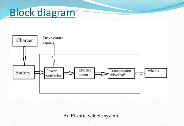
Powertrain of the vehicle: The powertrain of the vehicle consists of the battery, motor controller(inverter with drive signals), electric motor, transmission driveshaft, and wheels.
Battery stores the DC form of electricity.
As we are using a AC induction motor, DC to AC converter is needed. Also there is need of duty ratios to control the battery output voltage, in order to generate required output.
The motor controller does the work of inverting the supply from DC to AC and also generating the duty ratios.
Next comes the motor and then the trnsmission driveshaft to transfer the power to the wheels.
The image below shows the powertrain block diagram for electric towtractor.