wot condition
AIM : To understand the Wide Open Throttle(WOT)
OBJECTIVE:- To understand the Wide Open Throttle(WOT) Conditions on a vehicle and answer the following questions.
# Ques-1 Calculate the ratio of hill-climbing power required by a fully loaded tata ultra truck to the half-loaded one.
Given Data- For this question I am taking the details of the TATA T.16 ULTRA truck
Kerb weight = 6255 kg
Payload Capacity = 9765 kg
GVW(Gross Vehicle weight) = Kerb weight + Payload Capacity
m = GVW = 6255 + 9765 = 16020 kg
g = 9.81
Hill Climbing Angle = 10° (assumed)
Hill Climbing Force - Hill Climbing Force is the ability of a vehicle to climb on a typical hill or slope at a given constant speed. Usually upgradient(upwards) is considered for vehicle performance analysis Hill Climbing Force can also be represented as Gradability of vehicle.
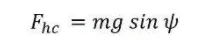
Fully Load Condition m1 = 16020 kg
Hill Climbing Force Fl = m1*g*siny = 16020 * 9.81 *sin(0.174533)= 27289.899
Half Loaded Condition m2 = 11133 kg
Hill Climbing Force F2 = m2*g*siny = 11133 * 9.81 *sin(0.174533) = 18964.946
Hill Climbing power (At constant speed) P1 = F1*v = 27289.899 * 80 = 2183191.92
Hill Climbing power (At constant speed) P2 = F2*v = 18964.946 * 80 = 1517197.12
The ratio of hill-climbing power required by a fully loaded tata ultra truck to the half-loaded one is- Ratio = p1/p2
Ratio = 2183191.92 / 1517197.12 = 1.43896
# Ques- 2 Calculate the minimum length of the flyover.
A flyover is planned to be constructed on a national highway. Keeping in mind the Gradeability for trucks, how much can be the minimum length of the flyover, considering the minimum height at the summit should be 5.5 meters.
Given:-Rise = 5.5 m Gradeability
Taking the Gradeability of TATA T.16 ULTRA truck (25.2%)
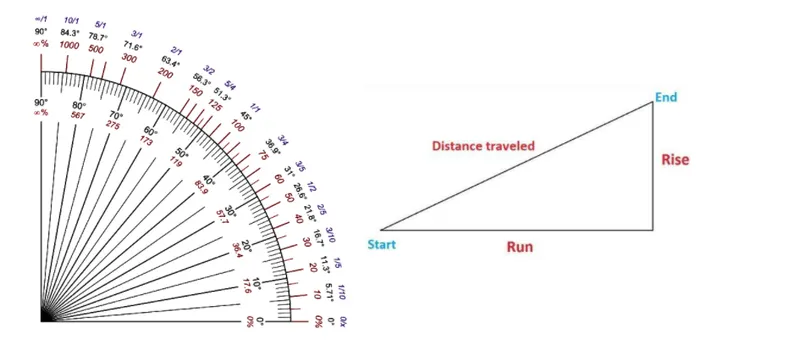
For 25.2% Gradeability the maximum slope angle is 15°
Length of Flyover = Rise /sin(15°)
5.5/sin(15°)=21.25m
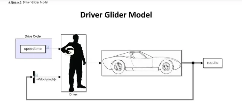
- For the Driver Glider Model, I create a Real Time Drive Cycle on an Excel sheet(speedtime), which includes speed variation with respect to time. - This Drive cycle (speedtime) excel sheet I import and save as numerical in MATLAB workspace. Then I use it as an input to the Driver. Using From Workspace block.
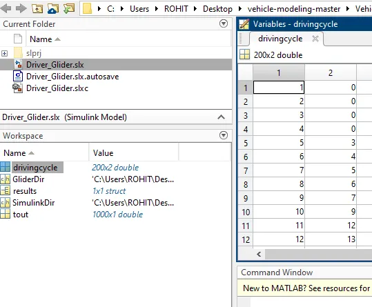
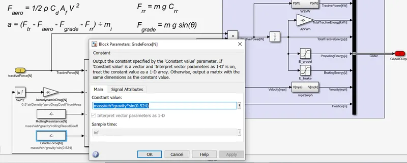
- Further to provide the Hill Climb Angle I edit in the Gradeability Force by providing the climbing angle.
RESULT:-
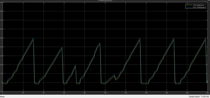
- Here from the Graph, it is shown that there is a salient difference in both the output.
This is because of the difference in the input values.
- After Giving these inputs Tractive Force is Calculated acting on the vehicle including all the Parameters & Losses.
- As per the requirement, I provided the Hill climbing angle to be 30°
- Due to Hill Climbing Force more power is required for the vehicle.
- Hence on giving the acceleration vehicle requires more power so, velocity get decreases at the time of acceleration.
- While applying brakes there is no such extra power required, so the graph is shown overlapping on braking.
QUES. NO. 4
GIVEN:-
total mass=185 kg
air density=1.25 per m^3
drag coeff.=0.75
frontal area=0.6 m^2
rolling resistance coeff.=0.007
gear ratio= 2
gear ratio eff.=98%
wheel radius=0.21
now motor characteristics eqn.
T=153-1.16w below critical speed
T=153-1.16 Gw/r above critical speed
taking T=34 N-m
now vehicle eqn
G*T/r=urr*m*g+0.625*cd*V^2+(m+5% extra)dv/dt
now putting all parameter we get Eqn.
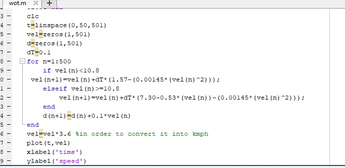
dv/dt=1.57-0.00145v^2 below critical speed
and
dv/dt=7.30-0.53v-0.00145v^2
code:
plot:-
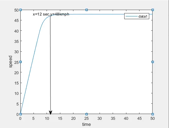
here we can see top speed is achieve at 12 sec which is 48kmph
case 1
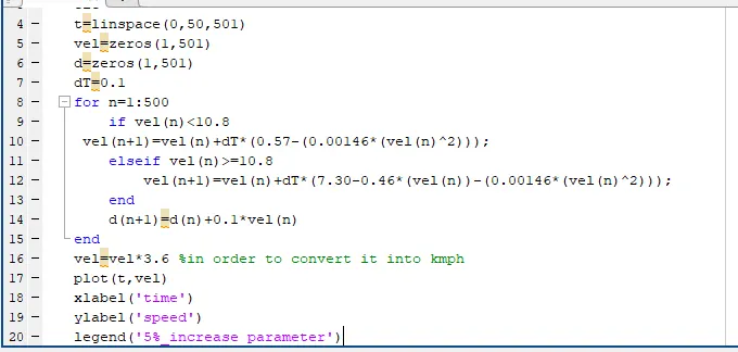
now with 5% increased parameter
eqn. below critical speed
dv/dt=0.57-0.00146v^2
and above critical speed
dv/dt=7.30-0.46-0.00146v^2
code:-
plot:-
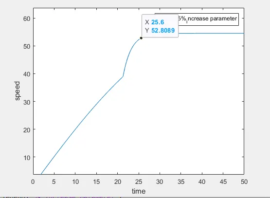
here we can see top speed is achieve at 25.6 sec which is 52kmph
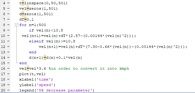
case 2:- with 5% decresed parameter
dv/dt=2.57-0.00144*v^2 below critical speed
dv/dt=7.30-0.66v-0.00144v^2
code:-
plot:-
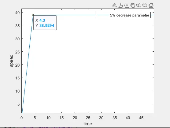
here we can see with 5% decresed parameter the top speed is 38.9kmph in 4.3 sec.