Project 1 (Mini Project on Vehicle Direction Detection
Objective of Mini Project:
- Development of MATLAB Simulink model as per requirement.
- Tag the requirements to the simulink model; tagging requirement 1 & requirement 2 to their corresponding subsystems is fine.
- MBD compliant changes, Data Dictionary creation & code generation is added advantage, and that is not scope of this project.
- If choosing code generation, Storage class for Input signals: ImportedExtern; Storage class for Output signal: Export to File; Storage class for local signals: localizable; Storage class for calibration signals: Const.
- Choose sample time for all signals as 0.01s
Requirement - 1:
- Steering wheel input as yaw rate (Signal name: SteeringWheel_YawDegreeInput) is the input for this system.
- This is compared against 3 angular values, one each for left turn, right turn & straight drive (Calibration Values: Right_Turn_AngularLimit, Left_Turn_AngularLimit, Straight_Drive_Steering_Angle) to say which specific direction the steering wheel is turning towards.
- Use switch blocks to compare & develop this requirement. Keep this requirement in a subsystem & output of this requirement is a local signal (Signal Name: Vehicle_Turn_Status).
Requirement – 2:
- Keep this requirement as a separate subsystem. Inputs to this requirement are local signal from requirement 1 (Signal Name: Vehicle_Turn_Status) & an input signal from camera (Signal Name: CameraInput_RoadSign), which confirms the occurrence of a road sign.
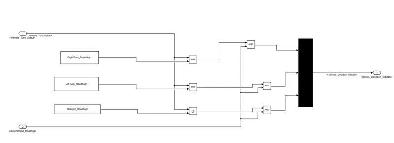
- Signal Vehicle_Turn_Status is compared against calibration values (Calibration Values: RightTurn_RoadSign, LeftTurn_RoadSign, Straight_RoadSign), if each of them is found equal, then each of the three corresponding output is compared against the camera input signal,
- Using a logical operator block, only one among them is finally given as output signal (Signal Name: Vehicle_Direction_Indicator).
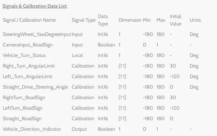
MAIN MODEL:-
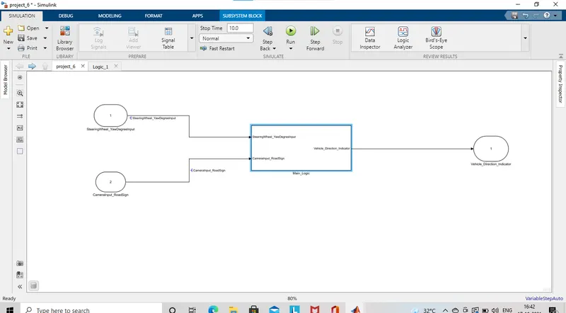
MAIN LOGIC:-
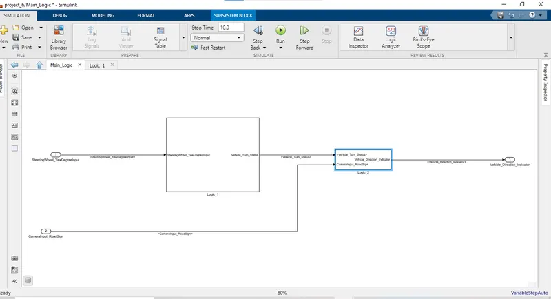
Requirement - 1:
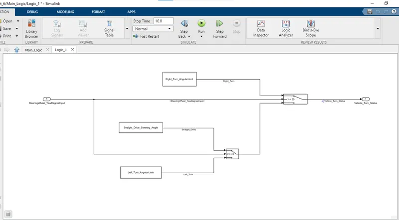
Requirement – 2:
• We have created the modlc as per the requirements given above.
• The requirement) is to create by inputting the SteeringWheel_YawDegreelnput comaparing this value by Right_Turn_AngularLimit, Left_Turn_AngularLimit, Straight_Drive_Stecring_Angle and the output is taken as Vehicle_Turn_Status.
• The requirement2 is created by inputting the Vehicle_Turn_Status along with the Camerainput _Roadsign. The value from the Vehicel_turn_status is compared with the RightTurn_RoadSign. LeftTurn_RoadSign. Straight_RoadSign the value which are equal gives that as output Vehicle_Direction_Indicator.
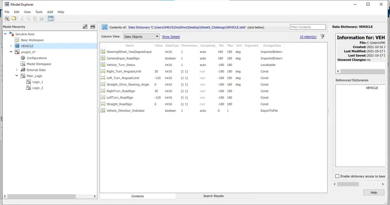
• Lets create a Simulink Data Dictionary and tag those to the model so that the values are propagated.
SLDD:-
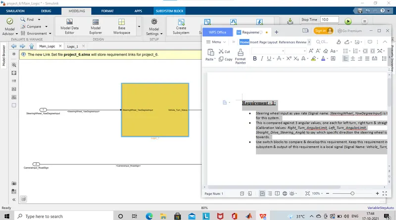
Requirement Tagging:-
Requirement - 1:
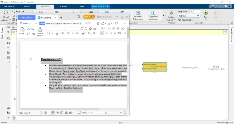
Requirement - 2:
ADVISOR REPORT
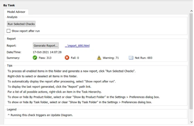
• Now lets generate code for the following model.
Code Generation:
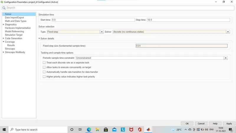
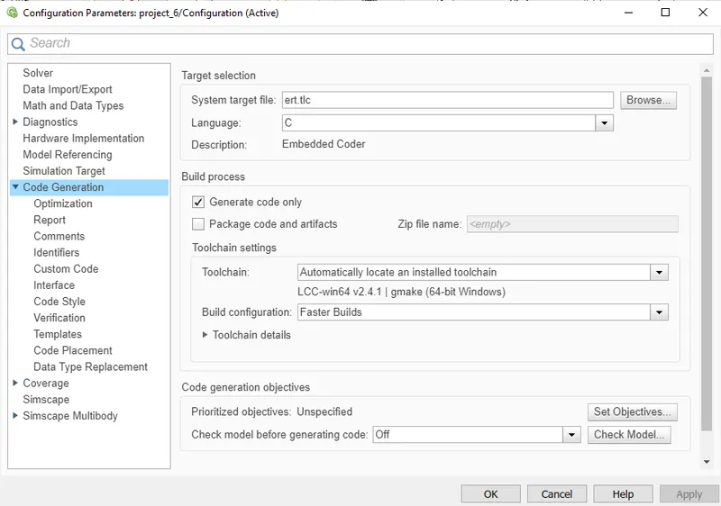
• For code generation firstly we need to configure the solver parameters and code genration parameters.
C CODE
/*
 * File: project_6.c
 *
 * Code generated for Simulink model 'project_6'.
 *
 * Model version                  : 1.2
 * Simulink Coder version         : 9.3 (R2020a) 18-Nov-2019
 * C/C++ source code generated on : Sun Oct 17 18:47:30 2021
 *
 * Target selection: ert.tlc
 * Embedded hardware selection: Intel->x86-64 (Windows64)
 * Code generation objectives: Unspecified
 * Validation result: Not run
 */

#include "project_6.h"
#include "project_6_private.h"

/* Exported data definition */

/* Const memory section */
/* Definition for custom storage class: Const */
const int16_T LeftTurn_RoadSign = -120;/* Referenced by: '<S3>/Constant1' */
const int16_T Left_Turn_AngularLimit = -120;/* Referenced by: '<S2>/Constant1' */
const int16_T RightTurn_RoadSign = 30; /* Referenced by: '<S3>/Constant' */
const int16_T Right_Turn_AngularLimit = 30;/* Referenced by: '<S2>/Constant' */
const int16_T Straight_Drive_Steering_Angle = 0;/* Referenced by: '<S2>/Constant2' */
const int16_T Straight_RoadSign = 0;   /* Referenced by: '<S3>/Constant2' */

/* External outputs (root outports fed by signals with default storage) */
ExtY_project_6_T project_6_Y;

/* Real-time model */
RT_MODEL_project_6_T project_6_M_;
RT_MODEL_project_6_T *const project_6_M = &project_6_M_;

/* Model step function */
void project_6_step(void)
{
  /* local block i/o variables */
  int16_T Vehicle_Turn_Status;

  /* Switch: '<S2>/Switch' incorporates:
   *  Constant: '<S2>/Constant'
   *  Constant: '<S2>/Constant1'
   *  Inport: '<Root>/SteeringWheel_YawDegreeInput'
   *  Switch: '<S2>/Switch1'
   */
  if (SteeringWheel_YawDegreeInput >= 30) {
    Vehicle_Turn_Status = Right_Turn_AngularLimit;
  } else if (SteeringWheel_YawDegreeInput >= 0) {
    /* Switch: '<S2>/Switch1' incorporates:
     *  Constant: '<S2>/Constant2'
     */
    Vehicle_Turn_Status = Straight_Drive_Steering_Angle;
  } else {
    Vehicle_Turn_Status = Left_Turn_AngularLimit;
  }

  /* End of Switch: '<S2>/Switch' */

  /* Outport: '<Root>/Vehicle_Direction_Indicator' incorporates:
   *  Constant: '<S3>/Constant'
   *  Constant: '<S3>/Constant1'
   *  Constant: '<S3>/Constant2'
   *  Inport: '<Root>/CameraInput_RoadSign'
   *  Logic: '<S3>/Logical Operator'
   *  Logic: '<S3>/Logical Operator1'
   *  Logic: '<S3>/Logical Operator2'
   *  RelationalOperator: '<S3>/Relational Operator'
   *  RelationalOperator: '<S3>/Relational Operator1'
   *  RelationalOperator: '<S3>/Relational Operator2'
   */
  project_6_Y.Vehicle_Direction_Indicator[0] = ((Vehicle_Turn_Status ==
    RightTurn_RoadSign) && CameraInput_RoadSign);
  project_6_Y.Vehicle_Direction_Indicator[1] = ((Vehicle_Turn_Status ==
    LeftTurn_RoadSign) && CameraInput_RoadSign);
  project_6_Y.Vehicle_Direction_Indicator[2] = ((Vehicle_Turn_Status <=
    Straight_RoadSign) && CameraInput_RoadSign);
}

/* Model initialize function */
void project_6_initialize(void)
{
  /* (no initialization code required) */
}

/* Model terminate function */
void project_6_terminate(void)
{
  /* (no terminate code required) */
}

/*
 * File trailer for generated code.
 *
 * [EOF]
 */