Mathematical Model of a Battery
Question
Run a MATLAB script for the mathematical model of lead acid battery and comment on it
Your Answers
Lead Acid Battery
Lead acid batteries are the most commonly used type of battery in photovoltaic systems. Although lead acid batteries have a low energy density, only moderate efficiency and high maintenance requirements, they also have a long lifetime and low costs compared to other battery types. One of the singular advantages of lead acid batteries is that they are the most commonly used form of battery for most rechargeable battery applications (for example, in starting car engines), and therefore have a well-established established, mature technology base.
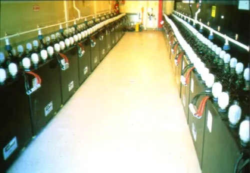
Working of Lead Acid Battery | Lead Acid Secondary Storage Battery
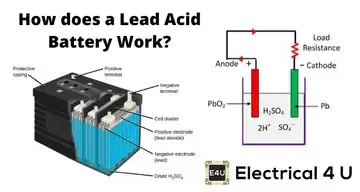
Working of Lead Acid Battery
The storage battery or secondary battery is such a battery where electrical energy can be stored as chemical energy and this chemical energy is then converted to electrical energy as and when required. The conversion of electrical energy into chemical energy by applying external electrical source is known as charging of battery. Whereas conversion of chemical energy into electrical energy for supplying the external load is known as discharging of secondary battery.
During charging of battery, current is passed through it which causes some chemical changes inside the battery. This chemical changes absorb energy during their formation.
When the battery is connected to the external load, the chemical changes take place in reverse direction, during which the absorbed energy is released as electrical energy and supplied to the load.
Now we will try to understand the principle working of lead acid battery and for that we will first discuss about lead acid battery which is very commonly used as storage battery or secondary battery.
Materials used for Lead Acid Storage Battery Cells
The main active materials required to construct a lead acid battery are
- Lead peroxide (PbO2).
- Sponge lead (Pb)
- Dilute sulfuric acid (H2SO4).
Lead Peroxide (PbO2)
The positive plate is made of lead peroxide. This is dark brown, hard and brittle substance.
Sponge Lead (Pb)
The negative plate is made of pure lead in soft sponge condition.
Dilute Sulfuric Acid (H2SO4)
Dilute sulfuric acid used for lead acid battery has a ratio of water : acid = 3:1.
The lead acid storage battery is formed by dipping lead peroxide plate and sponge lead plate in dilute sulfuric acid. A load is connected externally between these plates. In diluted sulfuric acid the molecules of the acid split into positive hydrogen ions (H+) and negative sulfate ions (SO4 − −). The hydrogen ions when reach at PbO2 plate, they receive electrons from it and become hydrogen atom which again attack PbO2 and form PbO and H2O (water). This PbO reacts with H2 SO4 and forms PbSO4 and H2O (water).

SO4 − − ions are moving freely in the solution so some of them will reach to pure Pb plate where they give their extra electrons and become radical SO4. As the radical SO4 cannot exist alone it will attack Pb and will form PbSO4.
As H+ ions take electrons from PbO2 plate and SO4 − − ions give electrons to Pb plate, there would be an inequality of electrons between these two plates. Hence there would be a flow of current through the external load between these plates for balancing this inequality of electrons. This process is called discharging of lead acid battery.
The lead sulfate (PbSO4) is whitish in color. During discharging,
- Both of the plates are covered with PbSO4.
- Specific gravity of sulfuric acid solution falls due to formation of water during reaction at PbO2 plate.
- As a result, the rate of reaction falls which implies the potential difference between the plates decreases during discharging process.
Now we will disconnect the load and connect PbSO4 covered with PbO2 plate with positive terminal of an external DC source and PbO2 covered with Pb plate with negative terminal of that DC source. During discharging, the density of sulfuric acid falls but there still sulfuric acid exists in the solution. This sulfuric acid also remains as H+ and SO4− − ions in the solution. Hydrogen ions (cation) being positively charged, move to the electrode (cathode) connected with negative terminal of the DC source. Here each H+ ion takes one electron from that and becomes hydrogen atom. These hydrogen atoms then attack PbSO4 and form lead and sulfuric acid.
SO4− − ions (anions) move towards the electrode (anode) connected with positive terminal of DC source where they will give up their extra electrons and become radical SO4. This radical SO4 cannot exist alone hence reacts with PbSO4 of anode and forms lead peroxide (PbO2) and sulfuric acid (H2SO4).
Hence by charging the lead acid storage battery cell,
- Lead sulfate anode gets converted into lead peroxide.
- Lead sulfate of cathode is converted to pure lead.
- Terminal; potential of the cell increases.
- Specific gravity of sulfuric acid increases.
As the above equations show, discharging a battery causes the formation of lead sulfate crystals at both the negative and positive terminals, as well as the release of electrons due to the change in valence charge of the lead. The formation of this lead sulfate uses sulfate from the sulfuric acid electrolyte surrounding the battery. As a result the electrolyte becomes less concentrated. Full discharge would result in both electrodes being covered with lead sulfate and water rather than sulfuric acid surrounding the electrodes. At full discharge the two electrodes are the same material, and there is no chemical potential or voltage between the two electrodes. In practice, however, discharging stops at the cutoff voltage, long before this point. The battery should not therefore be discharged below this voltage.
In between the fully discharged and charged states, a lead acid battery will experience a gradual reduction in the voltage. Voltage level is commonly used to indicate a battery's state of charge. The dependence of the battery on the battery state of charge is shown in the figure below. If the battery is left at low states of charge for extended periods of time, large lead sulfate crystals can grow, which permanently reduces battery capacity. These larger crystals are unlike the typical porous structure of the lead electrode, and are difficult to convert back into lead.
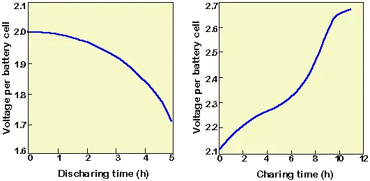
5.2.1 Voltage of lead acid battery upon charging.
The charging reaction converts the lead sulfate at the negative electrode to lead. At the positive terminal the reaction converts the lead to lead oxide. As a by-product of this reaction, hydrogen is evolved. During the first part of the charging cycle, the conversion of lead sulfate to lead and lead oxide is the dominant reaction. However, as charging proceeds and most of the lead sulfate is converted to either lead or lead dioxide, the charging current electrolyzes the water from the electrolyte and both hydrogen and oxygen gas are evolved, a process known as the "gassing" of the battery. If current is being provided to the battery faster than lead sulfate can be converted, then gassing begins before all the lead sulfate is converted, that is, before the battery is fully charged. Gassing introduces several problems into a lead acid battery. Not only does the gassing of the battery raise safety concerns, due to the explosive nature of the hydrogen produced, but gassing also reduces the water in the battery, which must be manually replaced, introducing a maintenance component into the system. In addition, gassing may cause the shedding of active material from the electrolyte, thereby permanently reducing battery capacity. For these reasons, the battery should not regularly be charged above the voltage which causes gassing. The gassing voltage changes with the charge rate.
Lead sulphate is an insulator, and therefore the way in which lead sulfate forms on the electrodes determined how easily the battery can be discharged.
5.3 Characteristics of Lead Acid Batteries
For most renewable energy systems, the most important battery characteristics are the battery lifetime, the depth of discharge and the maintenance requirements of the battery. This set of parameters and their inter-relationship with charging regimes, temperature and age are described below.
5.3.1 Depth of Discharge and Battery Capacity
The depth of discharge in conjunction with the battery capacity is a fundamental parameter in the design of a battery bank for a PV system, as the energy which can be extracted from the battery is found by multiplying the battery capacity by the depth of discharge. Batteries are rated either as deep-cycle or shallow-cycle batteries. A deep-cycle battery will have depth of discharge greater than 50%, and may go as high as 80%. To achieve the same useable capacity, a shallow-cycle battery bank must have a larger capacity than a deep-cycle battery bank.
In addition to the depth of discharge and rated battery capacity, the instantaneous or available battery capacity is strongly affected by the discharge rate of the battery and the operating temperature of the battery. Battery capacity falls by about 1% per degree below about 20°C. However, high temperatures are not ideal for batteries either as these accelerate aging, self-discharge and electrolyte usage. The graph below shows the impact of battery temperature and discharge rate on the capacity of the battery.
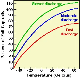
5.3.2 Battery Lifetime
Over time, battery capacity degrades due to sulfation of the battery and shedding of active material. The degradation of battery capacity depends most strongly on the interrelationship between the following parameters:
- the charging/discharging regime which the battery has experienced
- the DOD of the battery over its life
- its exposure to prolonged periods of low discharge
- the average temperature of the battery over its lifetime
The following graph shows the evolution of battery function as number of cycles and depth of discharge for a shallow-cycle lead acid battery. A deep-cycle lead acid battery should be able to maintain a cycle life of more than 1,000 even at DOD over 50%.
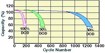
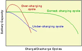
In addition to the DOD, the charging regime also plays an important part in determining battery lifetime. Overcharging or undercharging the battery results in either the shedding of active material or the sulfation of the battery, thus greatly reducing battery life.
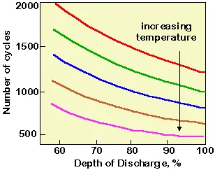
The final impact on battery charging relates to the temperature of the battery. Although the capacity of a lead acid battery is reduced at low temperature operation, high temperature operation increases the aging rate of the battery.
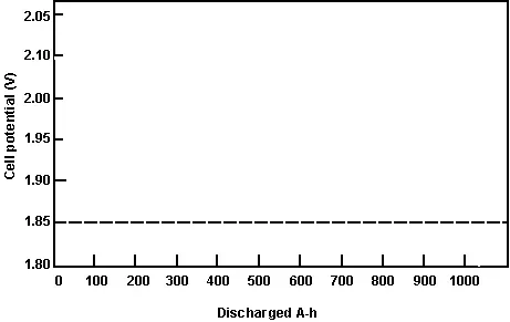
Constant current discharge curves for a 550 Ah lead acid battery at different discharge rates, with a limiting voltage of 1.85V per cell (Mack, 1979). Longer discharge times give higher battery capacities.
5.3.3 Maintenance Requirements
The production and escape of hydrogen and oxygen gas from a battery causes water loss and water must be regularly replaced in lead acid batteries. Other components of a battery system do not require maintenance as regularly, so water loss can be a significant problem. If the system is in a remote location, checking water loss can add to costs. Maintenance-free batteries limit the need for regular attention by preventing or reducing the amount of gas which escapes the battery. However, due to the corrosive nature the elecrolyte, all batteries to some extent introduce an additional maintenance component into a PV system.
5.3.4 Battery Efficiency
Lead acid batteries typically have coulombic efficiencies of 85% and energy efficiencies in the order of 70%.
5.4 Lead Acid Battery Configurations
Depending on which one of the above problems is of most concern for a particular application, appropriate modifications to the basic battery configuration improve battery performance. For renewable energy applications, the above problems will impact the depth of discharge, the battery lifetime and the maintenance requirements. The changes to the battery typically involve modification in one of the three basic areas:
- changes to the electrode composition and geometry
- changes to the electrolyte solution
- modifications to the battery housing or terminals to prevent or reduce the escape of generated hydrogen gas.
5.5 Special Considerations for Lead Acid Batteries
Flooded lead acid batteries are characterised by deep cycles and long lifetimes. However, flooded batteries require periodic maintenance. Not only must the level of water in the electrolyte be regularly monitored by measuring its specific gravity, but these batteries also require "boost charging".
Boost Charging
Boost or equalization charging involves short periodic overcharging, which releases gas and mixes the electrolyte, thus preventing stratification of the electrolyte in the battery. In addition, boost charging also assists in keeping all batteries at the same capacity. For example, if one battery develops a higher internal series resistance than other batteries, then the lower SR battery will consistently be undercharged during a normal charging regime due to the voltage drop across the series resistance. However, if the batteries are charged at a higher voltage, then this allows all batteries to become fully charged.
Specific Gravity (SG)
A flooded battery is subject to water loss from the electrolyte due to the evolution of hydrogen and oxygen gas. The specific gravity of the electrolyte, which can be measured with a hydrometer, will indicate the need to add water to the batteries if the batteries are fully charged. Alternately, a hydrometer will accurately indicate the SOC of the battery if it is known that the water level is correct. SG is periodically measured after boost charging to insure that the battery has sufficient water in the electrolyte. The SG of the battery should be provided by the manufacturer.
Special Considerations for Gelled, Sealed Lead Acid Batteries
Gelled or AGM lead acid batteries (which are typically sealed or valve regulated) have several potential advantages:
- they can be deep cycled while retaining battery life
- they do not need boost charging
- they require lower maintenance.
However, these batteries typically require a more precise and lower voltage charging regime. The lower voltage charging regime is due to the use of lead-calcium electrodes to minimise gassing, but a more precise charging regime is required to minimise gassing from the battery. In addition, these batteries may be more sensitive to temperature variations, particularly if the charging regime does not compensate for temperature or is not designed for these types of batteries.
5.5.1 Failure Modes for Lead Acid Batteries
The battery for a PV system will be rated as a certain number of cycles at a particular DOD, charging regime and temperature. However, batteries may experience either a premature loss in capacity or a sudden failure for a variety of reasons. Sudden failure may be caused by the battery internally short-circuiting due to the failure of the electrical separator within the battery. A short circuit in the battery will reduce the voltage and capacity from the overall battery bank, particularly if sections of the battery are connected in parallel, and will also lead to other potential problems such as overcharging of the remaining batteries. The battery may also fail as an open circuit (that is, there may be a gradual increase in the internal series resistance), and any batteries connected in series with this battery will also be affected. Freezing the battery, depending on the type of lead acid battery used, may also cause irreversible failure of the battery.
The gradual decline in capacity may be worsened by inappropriate operation, particularly by degrading the DOD. However, the operation of one part of the battery bank under different conditions to another will also lead to a reduction in overall capacity and an increase in the likelihood of battery failure. Batteries may be unintentionally operated under different regimes due either to temperature variations or to the failure of a battery in one battery string leading to unequal charging and discharging in the string.
Installation
Battery installation should be conducted in accordance with the relevant standard in the country in which they are being installed. At present, there are Australian standards AS3011 & AS2676 for battery installation. There is also a draft standard for batteries for RAPS applications which will eventually become an Australian standard.
Among other factors to be considered in the installation of a battery system are the ventilation required for a particular type of battery bank, the grounding conditions on which the battery bank is to be placed, and provisions taken to ensure the safety of those who may have access to the battery bank. In addition, when installing the battery bank care must be taken to ensure that the battery temperature will fall within the allowable operating conditions of the battery and that the temperature of the batteries in a larger battery bank are at the same temperatures. Batteries in very cold conditions are subject to freezing at low states of charge, so that the battery will be more likely to be in a low state of charge in winter. To prevent this, the battery bank may be buried underground. Batteries regularly exposed to high operating temperatures may also suffer a reduced lifetime.
5.5.2 Safety
Batteries are potentially dangerous and users should be aware of three main hazards: The sulfuric acid in the electrolyte is corrosive. Protective clothing in addition to foot and eye protection are essential when working with batteries.
Batteries have a high current generating capability. If a metal object is accidentally placed across the terminals of a battery, high currents can flow through this object. The presence of unnecessary metal objects (e.g. jewellery) should be minimised when working with batteries and tools should have insulated handles.
Explosion hazards due to evolution of hydrogen and oxygen gas. During charging, particularly overcharging, some batteries, including most batteries used in PV systems, may evolve a potentially explosive mixture of hydrogen and oxygen gas. To reduce the risk of explosion, ventilation is used to prevent the buildup of these gasses and potential ignition sources (i.e. circuits which may generate sparks or arcs) are eliminated from the battery enclosure.
5.5.3 Maintenance
Batteries introduce a periodic maintenance component into a PV system. All batteries, including "maintenance free" batteries require a maintenance schedule which should ensure that:
- the battery terminals are not corroded
- the battery connections are tight
- the battery housing should be free of cracks and corrosion.
Flooded batteries require extra and more frequent maintenance. For flooded batteries, the level of electrolyte and the specific gravity of the electrolyte for each battery needs to be checked regularly. Checking the specific gravity of a battery by using a hydrometer should be carried out at least 15 minutes after an equalisation or boost charge. Only distilled water should be added to batteries. Tap water contains minerals which may damage the battery electrodes.
5.5.4 Battery Disposal and Recycling
The lead in a lead acid battery presents an environmental hazard if it is not properly disposed of. Lead acid batteries should be recycled so that the lead can be recovered without causing environmental damage.
5.6 Electrode Materials and Configuration
The materials from which the electrodes are made have a major affect on the battery chemistry, and hence affect the battery voltage and its charging and discharging characteristics. The geometry of the electrode determines the internal series resistance and the charging and discharging rate.
5.6.1 Plate Material
The basic anode and cathode materials in a lead acid battery are lead and lead dixodie (PbO2). The lead electrode is in the form of sponge lead. Sponge lead is desirable as it is very porous, and therefore the surface area between the lead and the sulfic acid electrolyte is very large. The addition of small amounts of other elements to the lead electrode to form lead alloys can reduce several of the disadvantages associated with the lead. The main types of electrodes used are lead/antimony (using several percent antimony), lead/calcium alloys, and lead/antimony/calcium alloys.
Antimony lead alloy batteries have several advantages over pure lead electrodes. These advantages include: the lower cost of lead/antimony; the increased strength of the lead/antimony electrode; and the ability to be deeply discharged for short period of time. However, lead/antimony alloys are prone to sulfation and should not be left at low states of charge for extended periods of time. I addition, lead/antimony alloys increase the gassing of the battery during charging leading to high levels of water loss. Since the water must be added to these batteries, they have higher maintenance. Furthermore, lead/antimony batteries have a high discharge rate and a short lifetime. These problems (xx- check if both problems are caused by plating)) are caused by the dissolution of antimony from one electrode and its deposition or plating on the other electrode. (xx the increased adhesion of PbO2 xx)
Lead calcium batteries are an intermediate cost technology. Like antimony, calcium also adds strength to the lead of the negative electrode, but unlike antimony, the addition of calcium reduces the gassing of the battery and also produces a lower self-discharge rate. However, lead calcium batteries should not be deeply discharged. Consequently, these types of batteries may be considered "maintenance-free", but are only shallow cycle batteries.
Adding antimony as well as calcium to the electrodes provides some of the advantages of both antimony and lead, but at an increased cost. Deep discharge batteries such as these can also have a high lifetime. Furthermore, trace amounts of other materials can be added to the electrodes to increase battery performance.
5.6.2 Electrode Configuration
In addition to the material used to make the electrode plates, the physical configuration of the electrodes also has an impact on the charging and discharging rates and on the lifetime. Thin plates will allow faster charging and discharging, but are less robust and more prone to shedding of material from the plates. As high charging or discharging currents are not typically a required feature of batteries for renewable energy systems, thicker plates can be used, which have lower charge and discharge times, but also have longer lifetimes.
Definations and Governing equations:
Open Circuit Voltage (E): Open circuit voltage is a maximum theorital voltage that an battery can achieve. This voltage is not possible in actual conditions because of losses and internal resistance of the battery. OCV can be approximated by discharging the battery at a very low discharge rate (i.e.; around C/20).
State of Charge (SoC): SOC of a battery is defined as the ratio of its current capacity Q(t) to the nominal capacity Q. SoC shows how much charge/energy is available in the battery at a given instant of time. SoC ranges from 0 to 100%. SoC value depends on the previous behaviour(Hysteresis) of the battery and be calculated as, SoC = —Q(t) 100 where Q is the capacity.
Depth of discharge (DOD): It shows that amount of energy removed from a battery at a given instant of time DOD= Charge removed/Peukert's capacity also.
DOD = 1 - SoC
peukert's law:
Peukert's law expresses the battery capacity with respect to the rate of discharge. The law states that the discharge capacity of the battery dereases with the increase in the rate of discharge current Cp /k•T
where I . Current
T. Time
k= Peukert's coefficient. This constant has a value closer to 1 (in this cas 1.045). The coefficient k corelated the current at a given time.
Charge removed: Charge removes is the amount of energy removed from the total stored energy in the battery. The amount of energy removed is higher than the actual amount of energy supplied to the system. The charge removed also dependes on the behaviour of the battery in an earlier time step.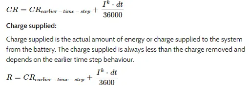
MATLAB CODE:-
%Mathematical Model of lead-Acid battery
clear all
close all
clc
%Defind inputs
%Defining time steps in variable T
T= (0:50:500000);%Total time 10001 steps with each time space of 50 sec.
CR= zeros(1,length(T)); % Charge removes (CR)
DOD= zeros(1,length(T)); %Depth of discharge
V= zeros(1,length(T)); % Voltage
CS= zeros(1,length(T)); %Charge supplied
E= zeros(1,length(T)); % Operating circuit voltage
I=[10,50,100,150,200]; %Current in Amphers
n=1; %No.of cells
C=50; %Capacity in Ah
k=1.045; %.045 represents loss of capacity due to discharge
dT= (T(2)-T(1))* ones(1,length(T)); %Time step
R_in= (0.06/C)*n; %Internal Resistance
E(1)=2.15;
for i= 1:length(I)
    V(i)=n*(2.15-I(i)*R_in);

    %Define the voltage equation for OCV
    for n= 2:length(T)
        dT(n)= T(n)-T(1);
        Cp=(I(i)^k)*(dT(n)); %Peukert's capacity
        CR(n)= (CR(n-1)+(dT(n)*(I(i)^k))/3600);
        DOD(n)=(CR(n)/Cp);
        E(n)=2.15-DOD(n)*(2.15-1.75);
        V(n)=E(n)-I(i)*R_in;
if DOD(n)>0.99
    E(n)=0;
    V(n)=0;
end
if DOD(n)>1
    DOD(n)=1;
end
if E(n)>0
    CS(n)=CS(n-1)+((I(i)*dT(n))/3600);
else
    CS(n)= CS(n-1);
end
    end
figure(1)
hold on
plot(DOD,V)
xlabel('D0D')
ylabel('Voltage')
end
plot(DOD, E)
legend('E-OCV','V-Voltage','I=10A','I=50A','I=150A','I=200A')
grid on


figure(2)
plot(DOD,E)
hold on
plot(DOD, V)
legend('E-OCV','V-Voltage')
xlabel('CR')
ylabel('Voltage')
grid on


figure(3)
plot(CR, E)
hold on
plot(CR, V)
legend('E-OCV','V-Voltage')
xlabel('CR')
ylabel('Voltage')
grid on

figure(4)
plot(CS,E)
hold on
plot(CS, V)
legend('E-OCV','V-Voltage')
xlabel('CS')
ylabel('Voltage')
grid on
Procedure:
• Initially defined the time step, Total time 10001 steps are defined with each time space of 50 sec.
• Defined the variables for mathematical model of CR, CS, DOD, V, Cp, E, n, I, C, k for improving the performance of the simulation.
• I is the discharge current and is taken as 10, 50, 100,150, 200. This are the diffenent discharge rates as C/5, 1C, 2C, 3C and 4C.
• I used two 'for' loops for the calculation. 1st 'for loop is used to calculate the run the inner commands for each value of discharge current I.
• Second 'for loop is the time loop and it calculates values of CR, CS, E, V and DOD repeats the simulation till the end of the defined time steps.
• loops are used such that voltage and OCV will drop when DOD reaches any value above 0.99 and further the value of DOD is considered as 1 (i.e.;the battery is assumed to be completely discharged).
• Next, the results are plotted using the plot command.
RESULTS:-
Open circuit voltage (E) & Battery discharge voltage (V) Vs Depth of discharge (DOD):
• This plot shows the variation of open circuit voltage and battery discharge voltage with respect to DOD. The difference between both the voltages is due to the internal resistance of the battery and other loose (temperature, chemistry etc).
Open circuit voltage (E) & Battery discharge voltage (V) Vs Depth of discharge (DOD) at different rates:
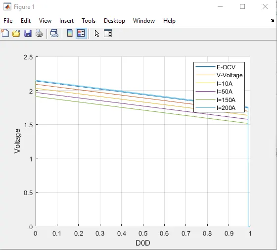
• From this plot, it shows that as the discharge rate increases the discharge capacity of the battery decreases. The topmost line is the open circuit voltage and is the maximum possible voltage that a battery can attain idcaly. But in the practical life this is impossible and by decreasing the dischargingg rate a close value to OCV can be obtained.
Open circuit voltage (E) & Battery discharge voltage (V) Vs Charge Supplies (CS):
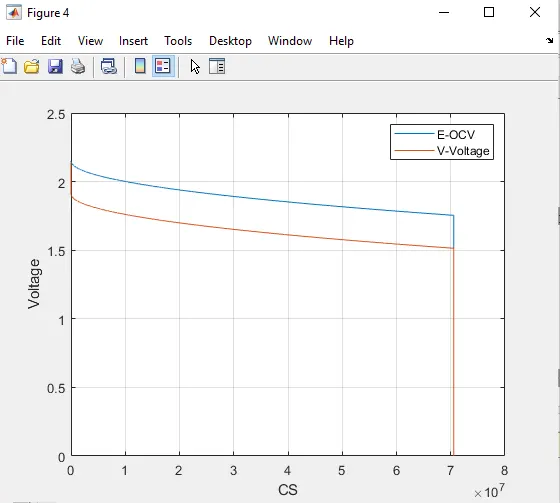
• This plot shows that the Open circuit voltage (E) & Battery discharge voltage (V) with respect to Charge Supplies (CS).
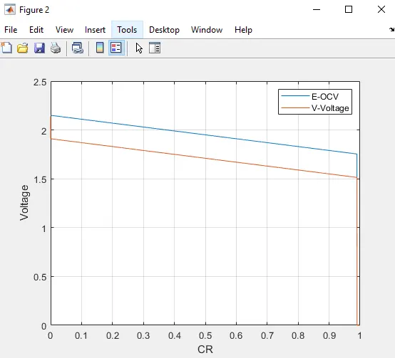
Open circuit voltage (E) & Battery discharge voltage (V) Vs Charge removed (CR):
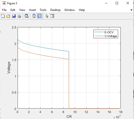
• This plot shows Open circuit voltage (E) & Battery discharge voltage (V) with respect to Charge removed. It can see that the charge removed is higher than charge supplied.
Conclusion: Hence created a MATLAB script for the mathematical model of lead acid battery.