Week 11-AUTOSAR Port Mapping
Question
• Create Autosar Port Mapping for the given input model.
• There are 20 inport & 20 outport signals in the model, so simply create runnables for these inport & outport signals.
• Input runnable must prefix Rp_, output runnable must prefix Pp_. Their Interfaces must prefix SRIf_ & their corresponding Data elements must prefix DE_.
• There is no trigger port in the model so need not create any specific runnables for trigger ports.
• Finally simulate the model once to check the changes, do not do code generation.
Your Answers
• Create Autosar Port Mapping for the given input model.
• There are 20 inport & 20 outport signals in the model, so simply create runnables for these inport & outport signals.
• Input runnable must prefix Rp_, output runnable must prefix Pp_. Their Interfaces must prefix SRIf_ & their corresponding Data elements must prefix DE_.
• There is no trigger port in the model so need not create any specific runnables for trigger ports.
• Finally simulate the model once to check the changes, do not do code generation.
In Simulink®, you can use the Code Mappings editor and the AUTOSAR Dictionary separately or together to graphically configure an AUTOSAR software component and map Simulink model elements to AUTOSAR component elements.
Use the Code Mappings editor to map Simulink model elements to AUTOSAR component elements from a Simulink model perspective. The editor display consists of several tabbed tables, including Functions, Inports, and Outports. Use the tables to select Simulink elements and map them to corresponding AUTOSAR elements. The mappings that you configure are reflected in generated AUTOSAR-compliant C code and exported ARXML descriptions.
The Code Mappings editor also provides mapping for submodels referenced from AUTOSAR software component models.
Simulink to AUTOSAR Mapping Workflow
To map Simulink model elements to AUTOSAR software component elements:
-
Open a model for which AUTOSAR system target file
autosar.tlcis selected. -
Create or open a mapped view of the AUTOSAR model. In the model window, do one of the following:
-
From the Apps tab, open the AUTOSAR Component Designer app.
-
Click the perspective control in the lower-right corner and select Code.
If the model has not yet been mapped to an AUTOSAR software component, the AUTOSAR Component Quick Start opens. To configure the model for AUTOSAR component development, work through the quick-start procedure and click Finish. For more information, see Create Mapped AUTOSAR Component with Quick Start.
The model opens in the AUTOSAR code perspective. This perspective displays the model and directly below the model, the Code Mappings editor.
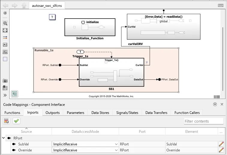
The Code Mappings editor provides in-canvas access to AUTOSAR mapping information, with batch editing, element filtering, easy navigation to model elements and AUTOSAR properties, and model element traceability. To view and modify additional AUTOSAR attributes for an element, select the element and click the
 icon.
icon. -
-
Navigate the Code Mappings editor tabs to perform these actions:
-
Map a Simulink entry-point function to an AUTOSAR runnable.
-
Map a Simulink inport or outport to an AUTOSAR receiver or sender port and a sender-receiver data element, with a specific data access mode.
-
Map a Simulink model workspace parameter to an AUTOSAR component parameter.
-
Map a Simulink data store to an AUTOSAR variable.
-
Map a Simulink block signal or state to an AUTOSAR variable.
-
Map a Simulink data transfer line to an AUTOSAR inter-runnable variable (IRV).
-
Map a Simulink function caller to an AUTOSAR client port and a client-server operation.
Use the Filter contents field (where available) to selectively display some elements, while omitting others, in the current view.
-
-
After mapping model elements, click the Validate button
 to validate the AUTOSAR component configuration. If errors are reported, address them and then retry validation
MAIN MODEL:-
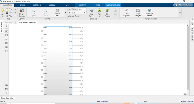
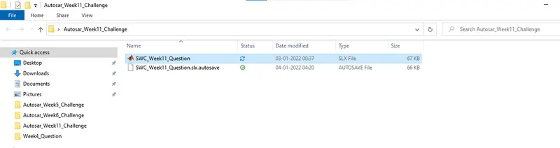
as per the naming convention of autosar the model name was changed and SWC_ was added to the model name
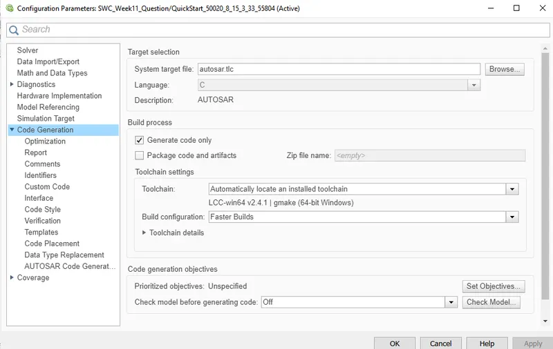
system target file was converted to autosar.tlc by going into the model setting and clicking on the code generation tab.
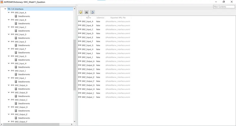
before creating inports and ourports ,interfaces were created in order to map the inports and outports,Interfaces were prefix SRIf_ & their corresponding Data elements were prefix DE_.
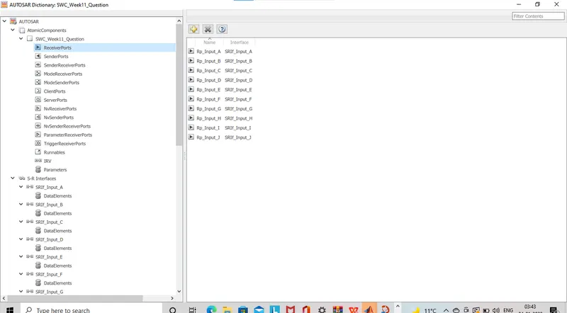
inports were created and
Input runnable were prefix Rp_
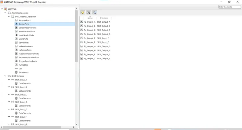
outports were created
output runnable were prefix Pp_
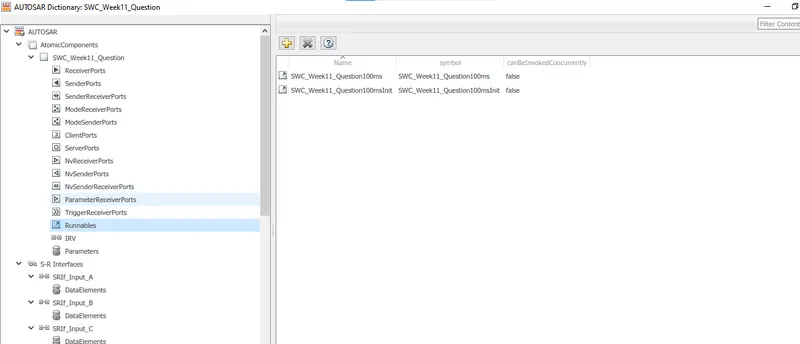
runnables were created ,one for intializing and other for time event, event were also created as Init event and TimingEvent.
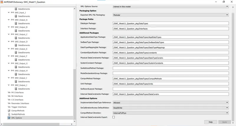
xml options were filled up which were as follows
/SWC_Week11_Question_pkg/DataTypes
/SWC_Week11_Question_pkg/Interfaces
/SWC_Week11_Question_pkg/DataTypes/ApplDataTypes
/SWC_Week11_Question_pkg/DataTypes/SwBaseDataTypes
/SWC_Week11_Question_pkg/DataTypes/DataTypeMappings
/SWC_Week11_Question_pkg/DataTypes/constants
/SWC_Week11_Question_pkg/DataTypes/DataTypeConstrs
/SWC_Week11_Question_pkg/DataTypes/SystemConstants
/SWC_Week11_Question_pkg/DataTypes/CompuMethods
/SWC_Week11_Question_pkg/DataTypes/Units
/SWC_Week11_Question_pkg/DataTypes/DataConstrs
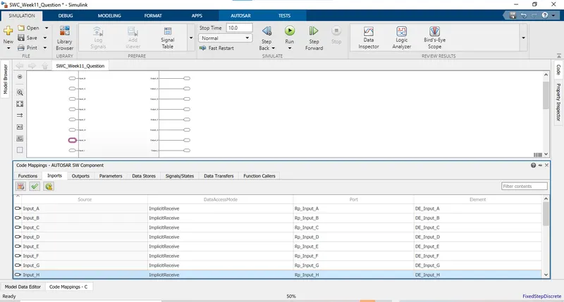
mapping of inports was done with the corresponding data elements.
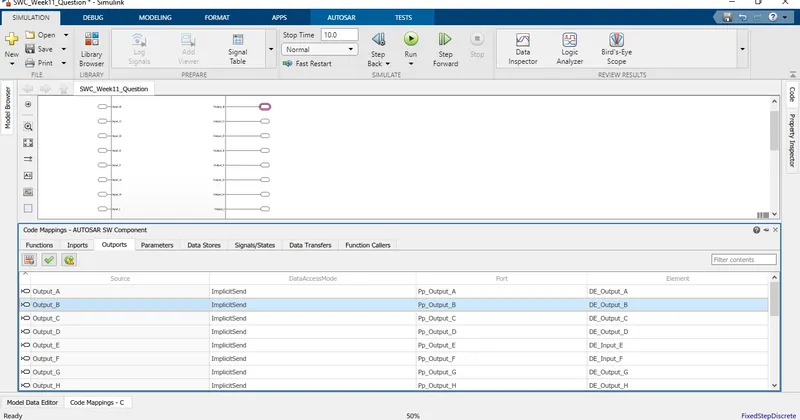
mapping of outports was done with the corresponding data elements.
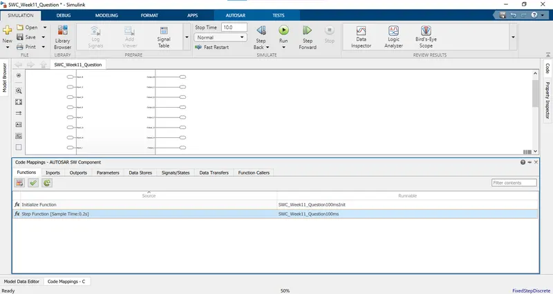
functions were created one for intilizing and one for sample time, model was runned and validated with AUTOSAR SW Component.