Induction Motor-2
Your Answers
1. Discuss about the equivalent circuit network of induction motor MATLAB model.
2. 3 phase, 50 Hz induction motor, represented by equivalent circuit constants XI = X2 = 0.1 ohm and RI = R2 = 0.2 ohm is operated at half of rated voltage and frequency. Calculate the ratio of starting torque at half voltage & frequency to rated values.
3. Make a MATLAB script file which will plot speed torque characteristics for frequency control method.
ANS 1:
In MATLAB, the block for an induction motor powered by an AC supply is shown below:
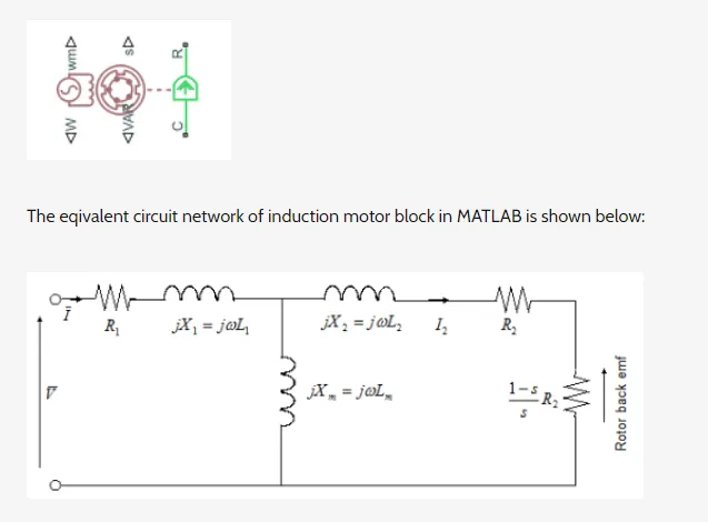
In the above circuit, the various terms are as follows:
• Stator resistance - R1
• Rotor resistance - R2
• Stator inductance - L1
• Rotor inductance - L2
• Magnetizing inductance - Lm
• Rotor slip - s
• Sinsuoidal supply voltage - V
• Sinusoidal current phasors - I
• Rotor Current - I2
Working Principle: An induction motor consists of a stationary component called the stator and a rotary component called the rotor. The stator consists of 3 coil windings supplied with 3 phase AC power which are wound around stacks of thin, highly permeable laminations in a cast iron or steel frame. Changing the frequency of the 3 phase supply power supply (i.e. the sinusoidal supply voltage and current phasors) will generate a rotating magnetic field. This induces an emf and therefore a current in the rotor when the magnetic field interacts with the rotor via eletromagnetic induction. But now that the rotor is a current carrying conductor in the rotating magnetic field, it will experience an electromagnetic force producing a torque via the motor effect.
Since an emf is induced in the rotor, there will be a current flowing through it and this is denoted as: I2
The induced emf in the rotor as a result of electromagnetic induction is also referred to as the 'back emf' and it is shown in the equivalent circuit diagram as well. This emf is referred to as 'back emf because it acts in the opposite direction to the direction of the 3 phase voltage across the coil windings in the stator. The magnetizing inductance, Lm is required at the air gap because across it is the boundary between the stator and the rotor. The stator will produce the rotary magnetic field and it needs to cross the air gap to interact with the rotor to excite it to produce a torque. So the magnetizing inductance, Lm is needed to cross this air gap. Xm, X1 and X2 all represent reactance values. Reactance is a form of opposition that electronic components exhibit to the passage of current through them due to their capacitance or inductance properties.
Operation: The speed of the rotating magnetic field is also known as the synchronous speed and it is dependent on the frequency of the 3 phase power supply and the number of poles of the induction motor. So, the frequency of the 3 phase power suppply is proportional to the synchronous speed and also the motor speed. The synchronous speed is determined by the formula below: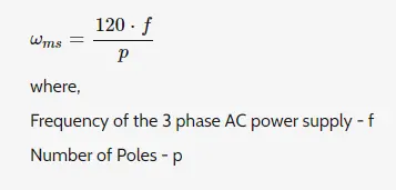
This synchronous speed needs to be greater than the motor speed because if the synchronous speed is greater than the rotor speed, there will be an interaction between the magnetic field and the rotor bringing about excitation. It is this excitation that induces the emf in the rotor, causing it to experience the electromagnetic force thus producing the torque. The slip is basically the phase difference between the synchronous speed and the rotor speed. The slip varies between 0 and 1 and it is a maximum when the rotor speed is equal to the synchronous speed. In the former case, there will be no torque because there will be no interaction between the rotating magnetic field and the rotor. In the latter case, this is referred to as the starting torque and this is the highest torque that is produced by the induction motor. For this model, the slip is mathematically expressed in terms of the motor speed, the number of poles and the frequency of the 3 phase power supply as so:
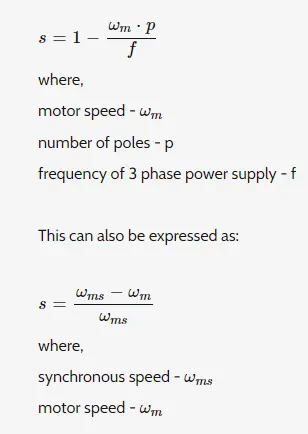
number of phases - n
Stator Inductance - X1
Rotor Inductance - X2
Root mean square Voltage - Vm

The block can be modified in terms of the parameters mentioned below the equivalent circuit model or in terms of the motor ratings. From the block we can see that there are 2 mechanical ports, C and R. When the block is used in a simulation, a positive torque is produced acting from those ports. The block also has 2 thermal ports, one for each winding and they are mainly used to simulate the copper resistance losses that occur which are in the form of heat energy.
To see these ports, we need to right click on the block, and from the options select 'Simscapec then 'Block Choices' and then 'Show Thermal Port
While the simplified induction motor block can model the torque speed characteristics of an induction motor there are still some limitations that it has. For instance, it does not model the starting mechanism for a single phase induction motor.
Another limitation is that if the block is modelled in terms of the motor rating parameters, then the equivalent circuit model parameters are derived by assuming that the magnetizing inductance term, Lm is negligible. Hence, the effect of the magnetizing inductance term will not be included in the simulation.
#Ques 2- 3 phase, 50 Hz induction motor, represented by equivalent circuit constants X1 = X2 = 0.1 ohm and R1 = R2 = 0.2 ohm is operated at half of rated voltage and frequency. Calculate the ratio of starting torque at half voltage & frequency to rated values.
Given-
number of Phases = 3
Rated Frequency (f) = 50hz
Stator - X1 = 0.1 ohm & R1 = 0.2 ohm
Rotor - X2 = 0.1 ohm & R2 = 0.2 ohm
Formula used-
1) Torque speed relation
`ω_m` = actual speed of rotor/speed of the motor
ωms - Synchronous speed of the motor (based on supplied frequency)/number of poles(P)
`ω_(ms) = (120 times f) / p`
2) We have seen, the actual speed & synchronous speed are having a difference in them which is called Slip.
`s = (ω_(ms) - ω_m) / (ω_(ms))`
3) Using Kirchhoff's Law established Torque equation is given by
`T = 3/(ω_(ms)) [(V^2 times (R_2/s)) / ((R_1 + R_2/s)^2 + (X1+ X2)^2 )]`
Solution-
Since at starting Torque (Torque speed =0) or 0-condition,
slip =1,we get the starting Torque as,-
`T = 3/(ω_(ms)) [(V^2 times R_2) / ((R_1 + R_2)^2 + (X1+ X2)^2 )]`
The synchronous speed of the motor-
| For Full Rated Frequency (50hz) | For Half rated Frequency (25hz) |
|
`ω_(ms1) = (120 times 50) / P` `ω_(ms1) = 6000 / P` |
`ω_(ms2) = (120 times 25) / P` `ω_(ms2) = 3000 / P` |
From above we found that, the Synchronous speed at Full Rated Frequency is double of Half Rated Frequency.
`ω_(ms1) = 2 times ω_(ms2)`
Now Starting Torque-
| For Full Rated Voltage (V) | For Half rated Voltage (V/2) |
| `T_1 = 3/(ω_(ms1)) [(V^2 times R_2) / ((R_1 + R_2)^2 + (X1+ X2)^2 )]` | `T_2 = 3/(ω_(ms2)) [(V^2 times R_2) / ((R_1 + R_2)^2 + (X1+ X2)^2 )]` |
| `T_1 = 3/(2 times ω_(ms2)) [((V)^2 times 0.2) / ((0.2 + 0.2)^2 + (0.1 + 0.1)^2 )]` | `T_2 = 3/(ω_(ms2)) [((V/2)^2 times 0.2) / ((0.2 + 0.2)^2 + (0.1 + 0.1)^2 )]` |
| `T_1 = 3/(2 times ω_(ms2)) [((V)^2 times 0.2) / 0.2 ]` | `T_2 = 3/(ω_(ms2)) [((V^2/4) times 0.2) / 0.2 ]` |
| `T_1 = (1.5 times V^2)/(ω_(ms2))` | `T_2 = (0.75 times V^2) /(ω_(ms2))` |
Now the ratio of Starting Torque will be -
Starting Torque at Half Rated / Starting Torque at Full Rated = `T_2/T_1`
`T_2/T_1 = [(0.75 times V^2) /(ω_(ms2))] / [(1.5 times V^2)/(ω_(ms2)) ]`
`T_2/T_1 =[(0.75 times V^2) /(ω_(ms2))] times [(ω_(ms2)) / (1.5 times V^2)]`
`T_2/T_1 = 1/2`
Therefore the ratio of starting torque at Half voltage & Half frequency(T2) to Rated voltage & Rated frequency(T1) is
T2 : T1 = 1 : 2
#Ques 3- Make a MATLAB script file that will plot speed-torque characteristics for the frequency control method.
Matlab Program-
clear all
close all
clc

% Speed - Torque Characteristics for Frequency conrol method

V1 = 230/sqrt(3); % 12Kwh battery
ph = 3; % Number of phases
P = 4; % Number of poles
fe = linspace(10,50,5); % Frequency

% Stator Resistance[R1] & Inductance[X1]
R1 = 0.050;
X1 = 0.630;

% Rotor Resistance[R2] & Inductance[X2]
R2 = 0.30;
X2 = 0.672;

Xm = 17.7; % Magnetizing Inductace


% Calculate the Stator Thevenin Equivalent
Zl_eq = 1i*Xm*(R1+1i*X1)/(R1 + 1i*(X1+Xm));
Rl_eq = real(Zl_eq);
Xl_eq = imag(Zl_eq);
Vl_eq = abs(V1*1i*Xm/(R1 + 1i*(X1+Xm)));

for i = 1:length(fe)

    % Calculate the Synchronous speed
     wm = 4*pi*fe(i)/P;
     w_ms = 120*fe(i)/P;

for n = 1:200
    s(n) = n/200; % Slip
    rpm(n) = w_ms*(1-s(n)); % Speed of Motor [rpm]
    I2 = abs(Vl_eq / (Zl_eq + 1i*X2 + R2/s(n))); % Rotor Current
    T_s(n) = ph*I2^2*R2/(s(n)*wm);
end

% Plotting speed-torque characteristics for the frequency control method
plot(rpm, T_s)
hold on
grid on
title('Torque-Speed Characteristics of Induction Motor')
xlabel('Speed [rpm]')
ylabel('Torque [N-m]')
legend('10Hz','20Hz','30Hz','40Hz','50Hz')
end- 3-Phase, 4-Poles, & 12Kw Induction Motor is considered for simulation.
- Since this is the Frequency Control method, I created an array using Linspace for different Frequency operation
- Nominal values for Stator & Rotor Resistance & Inductance are provided.
- Then we calculated the Synchronous Speeds and the starting Torque of the Motor
- Synchronous speed & Torque has been calculated for different Frequency operation.
- Torque-Speed Curves at different Operating frequencies are plotted
Result-
- It is observed from the Graph, that with an increase in the frequency the Motor Speed is increasing.
- It is also shown in the Graph that the Maximum Torque is reducing with an Increase in Speed.
- In order to get an Optimal Working range, along with Frequency the Supply Voltage has to change accordingly.
- So it can be concluded that the Voltage-Frequency ratio control method will be the best alternative to this method