Week 10 - Challenge 2- Attachment Feature Creation (Dog House)
OBJECTIVE: To create the Door Trim Plastic Component from the given Class A Surface & then create two dog houses as attachment features for it while following the given Design Guidelines.
INTRODUCTION
DOG HOUSE
Dog house is an engineering feature used in plastic design. Dog houses are used as support feature. Sometimes other engineering features like snaps, locators, screw bosses are mounted on them to increase their strength.
Dog houses are subjected to draft analysis to prevent breakage of the component during ejection from the mould cavity. Dog house and oher engineering components are built on the B-surface.
OBJECTIVE
- Create Tooling axis for the given CLASS -A surface.
- Create the CLASS B and C surfaces of door trim using the given CLASS-A surface.
- Create final surface model and convert it into solid body using close surface command in the part design workbench.
- Create side core axis for the dog house
- Create Dog house on the B surface by considering the design rules.
- Perform draft analysis for both Class-A surface and Final part body.
Design Methodology
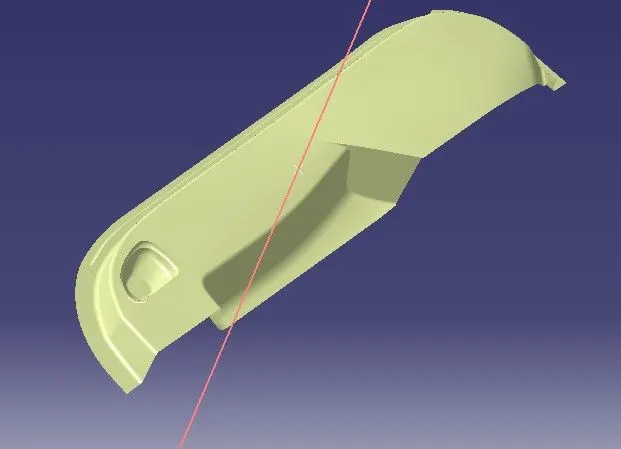
Class-A surface means visible surface. It gives the aesthetic of the component which is created by the styling team and gives to the part design engineer to create the part with all engineering aspects.
Tooling axis Creation
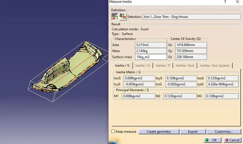
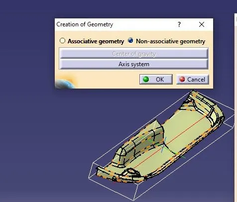
In injection molding, the Class A surface is first analyzed to determine the axis or tooling direction that separates the molds. Tooling direction is critical for plastic product design because it determines mold direction.
Draft Analysis
For molded or cast parts, the draft angle is the amount of taper perpendicular to the parting line. It is measurable in degrees. Because plastic shrinks and sticks on molding surfaces as it cools, we draft the walls of the plastic part so that it ejects or breaks free from the molding surfaces more easily and without dragging. To reduce the risk of damage to the parts and ensure ejection, a functional injection molding part must have drafts on both the cavity and core sides.
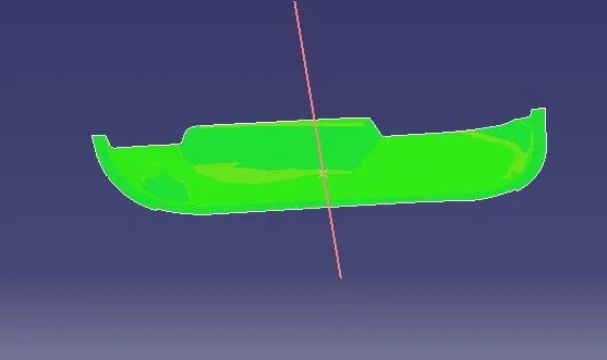
Nominal values for Draft angles
- 3 Degrees is a nominal draft angle
- 5 Degrees can also be manufactured. Increasing the manufacturing cost
- 7 Degrees is considered for Textured surface parts
Importance of Draft in injection molding
- Reduces the possibility of part damage due to friction during the release
- Reduces mold wear and tear
- Ensures a uniform, smooth, unscratched finish
- Ensures the integrity and uniformity of other surface finishes and textures
- Reduces overall cooling time by reducing or eliminating the need for unusual ejection setups
Steps followed for Draft Analysis
- The created part must be changed to the material mode in the display frame
- Compass is enabled and placed in the direction of the Tooling Axis
- The lock command is then used to fix the compass along the tooling axis
- Color codes are classified and a Draft angle is applied
- Running point analysis is used to display permissible draft angle
Class A Surface-
Visible surface is a Class-A surface. It provides the style team's look for the component, which the part design engineer uses to develop the component with all of the engineering requirements.
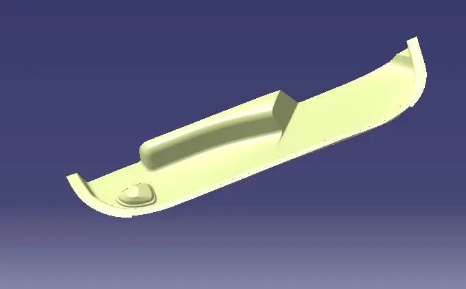
Creating Class B Surface:
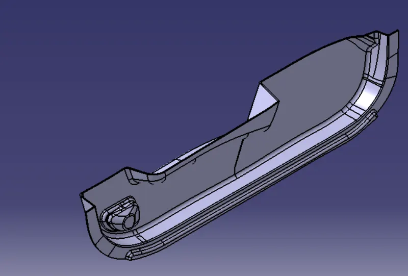
First, offset the surface to 2.5mm, some errors may occur and some parts got removed. Click keep all sub-elements. And use fill, sweep, boundary, extrapolate, and trim commands to close the patches. Then join all together
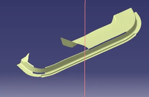
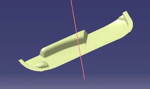
CREATION OF CLASS C SURFACE:
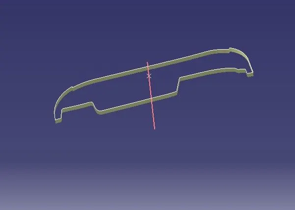
We first extract the edges from the Class A surface with the help of the multi extract or boundary command which we create the path for a sweep for class C
like this, we have to create all separate sweeps and join them together. once all the sweeps are joined together we created a class c surface.oining class A surface and class c surface together
Then trim the class-B surface to join (A+C) this will make sure that we get a closed surface. We can check it using the boundary tool, if it gives an error that means that the component is closed.
Conversion of Closed surface into Solid Part
Using Solid Command, we convert the closed surface to a solid surface in the Part model.
Creating B Surface Attachment Feature Dog House
Creating Dog House on B Surface
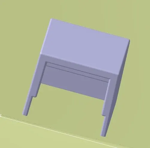
Dog houses are designed to avoid Sink marks created on the CLASS-A surface by screw bosses and to solve the length issues when giving screw bosses which need to be assembled to other components. It is also useful when perpendicular screw bosses are required on the part of the tooling direction.
The dog house is an engineering feature used in the plastic trim design. Dog houses are used as supporting features. Sometimes other engineering features like snaps, locators, etc. are mounded on them to increase their strength. Dog house and other engineering Features are built on B-surface.
Design Rules For Dog House Creation
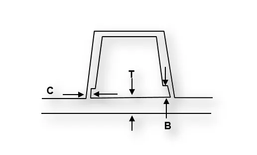
"C" is where the doghouse contacts the backside of the surface
Doghouse wall thickness at the intersection of the part wall (C) should be 40% or less than the main wall stock (T).
The height of (B) should be between 3.0 – 6.0 mm
C 40 % of T or ≤ T
B 3 - 6 mm
Width ≥12 mm
Width to Height Ratio 3:1
Draft 1.5
DRAFT ANALYSIS
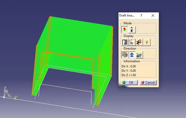
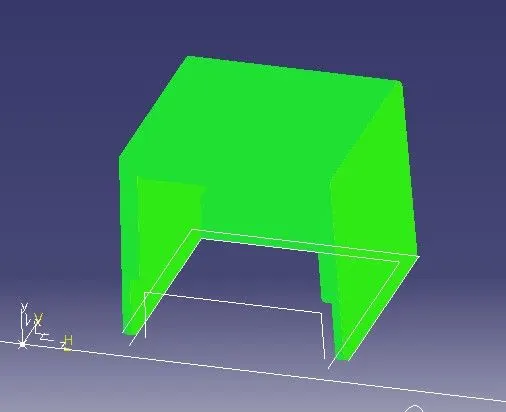
The Draft Analysis is a command enables you to detect if the part you drafted will be easily removed. This type of analysis is performed based on colour ranges identifying zones on the analysed element where the deviation from the draft direction at any point, corresponds to specified values.
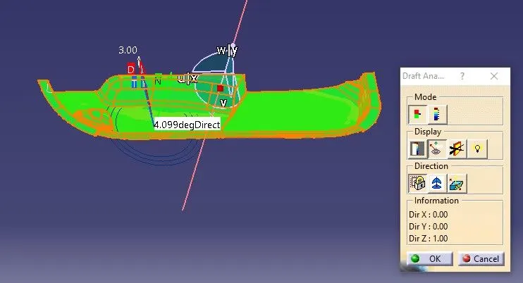
Draft analysis is done after determining the tooling axis, draft analysis is used to check whether the minimum draft (3 degrees) is maintained or not.
- Procedure for performing the draft analysis are as follows
- Change the view mode of the component to be in customized parameter mode and then select the shading mode as materials.
- Then open the featured draft analysis tool from the insert menu.
- Then click on use the compass to define the current drafting direction and then drag and align the compass on the Tooling axis.
- Then lock the draft direction and perform draft analysis by clicking on the component.
Colour Range representation
GREEN colour - Positive Draft
RED colour – Zero draft
BLUE colour – Negative Draft
Conclusion
i have successfully created CLASS B and C surfaces using the given CLASS A surface of door trim and craeted main tooling axis and side core tooling axis. Performed draft analysis for both final component and the dog house.