Roof Design
-ROOF DESIGN-
OBJECTIVE-
- The objective of the project is to design car roof with essential flanges and reinforcements like ditch area, front roof rail, bow roofs, center roof rail, for the given styling surface. And also understand the design process and learn about the different tools used in NX cad for designing.
- Do curvature study on roof and performance calculation for heat distortion and snow load criteria to determine the position of the bow roofs.
- Find the moment of inertia and section modulus for Bow-roofs and center roof rail.
- We will find the draft analysis of each part, that we will be designed.
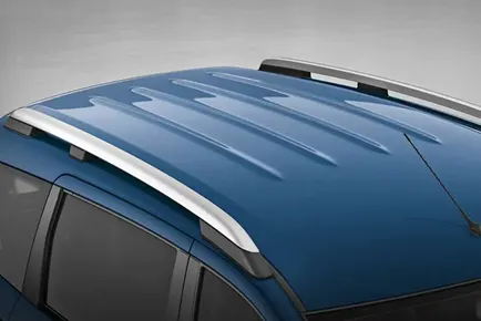
Materia used-
Steel is the most used of the materials, marking it less expensive and affordable as a metal roofing option for homeowners as well as commercial builds.
- Mostly metal use for roof
- Copper
- Aluminum
- Zinc
- Steel
- Tin
METHODOLOGY-
- We get the model of the roof from the styling team. Then we will do all engineering work. We will create ditch area for the roof bows and roof rails for the roof which would we designed by us considering all safety parameters and regulations.
INTRODUCTION-
- An automobile roof or car top is the portion of an automobile that sits above the passenger’s compartment, protecting the vehicle occupants from sun, wind, rain and other external effect. Because the earliest automobiles were designed in an era of house-drawn carriage, early automobile roofs used similar materials and designed.
Type of car roof-
- Hardtops
- Sunroof
- Pop-up
- Spoiler
- Panoramic sunroof
- Convertibles
- Retractable hardtop
- Detachable hardtop
- Soft tops
- The T-top roofs-
- Hardtops-
When we talk about hardtops, we are referring to the common rigid forms of automobile roofs which we see around us, in modern day cars, this type of roof is made from metal or plastic. So, the common Toyota corolla, Camry, and many of the cars in Nigeria and all hardtops. However, we should say that there are different types. The one we just described Is the fixed hardtop. Other type includes:
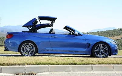
- The detachable hardtops
- The retractable hardtops
- Sunroof-
A sunroof is a panel on the roof of a car that either slides back or can be taken out to allow light, air or both to come into a vehicle.
- Pop-up sunroof- The least expensive of all the sunroofs, the Pop-up Sunroof is usually a manually operated tilting panel that does not fully retract. In some models, the pop-up roof is entirely detachable.
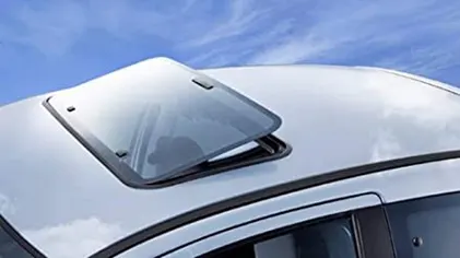
- Spoiler sunroof-
Also known as Tilt or Sliding Sunroof, it is similar to the Built-in sunroof version, with the main difference being the sunroof sliding on top of the car rather than in between the car's roof. The sunroof tilts and slides open on the car's roof almost 60% of the way. This sunroof version is perfect for compact cars, sliding back to provide ventilation.
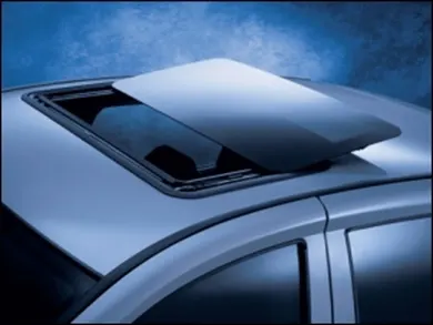
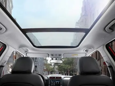
- Panoramic sunroof-
The latest feature available in cars right now is the Panoramic sunroof. This multi-panel sunroof covers a large area front and back, allowing everybody in the car to enjoy fresh air and light.
- Convertible roof-
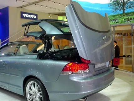
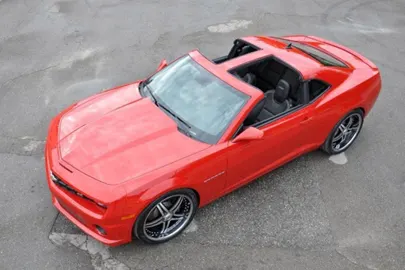
As the name say convertible roof, that means driver can driver the car with roof or without roof. a car with a foldable or removable roof is called a convertible car. Such cars can transform from a roof-top model to an open-top model within a few minutes. The roof can be a hard or soft top. Open-top cars are also called cabriolets or drop-top cars.
- Retractable hardtops roof-
This type of car roof made from metal or plastic and is retracted automatically.
- Detachable hardtops roof-
This type of roof is manually removed from the roof and then stored usually in the truck. They are also made from metal or plastic.
- T-top roof-
T-top roof is an automobile roof with a removable panel on each side of a rigid bar running from the center of one structural bar between pillars to the center of the next structural bar? The panels of a traditional T-top are usually made of auto grade safety glass.
Reinforcement-
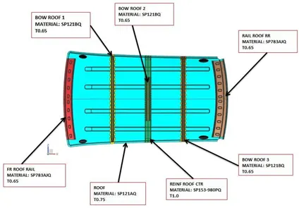
If the roof is flat will be very week and cannot able to with stand the force like snow, so in order to increase the strength of the roof these reinforcement like front rail, rear roof rail and the bow roofs are introduced and joined to the flat surface to the roof with the different joining process.
Reinforcement of roof-
- Front roof rail
- Bow roof rail
- Center roof rail
- 4-Rear roof rail
1-Front roof rail-
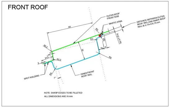
This is the reinforcement provided at front. This part is joined to BIW body and windshield. Visibility criteria is taken in account for joining it with windshield, it is fixed to BIW with spot welds and roof surface is attached with the help of mastic sealants. A draft angle is provided for deep drawing operation. Draft analysis is also done on the section to check its manufacturing ability.
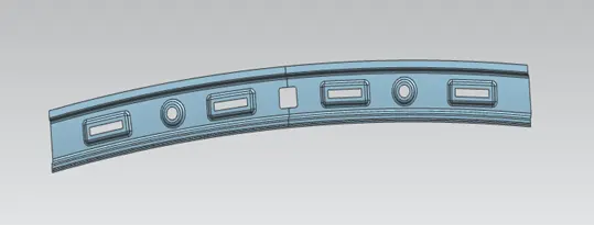
2-Bow roof rail-
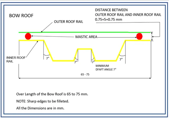
Bow roof is an additional stiffening member for the roof to increase the strength and so that it can satisfy the norms. Both the ends are joined together using mastic sealants to increase strength and also since this would not affect the styling of the roof.
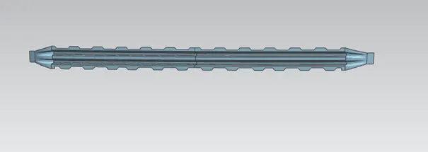
3-Center roof rail-
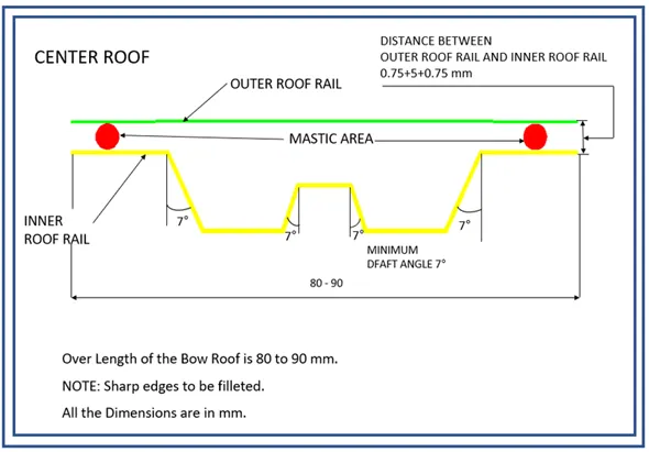
Centre roof rail or the reinforcement center is located at the center of the roof. The cross section of this is more since it needs to provide more strength to the roof. Here both are ends are joined together using mastic sealants.
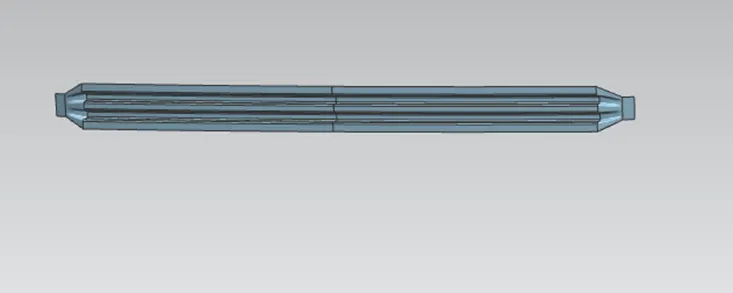
4-Rear roof rail-
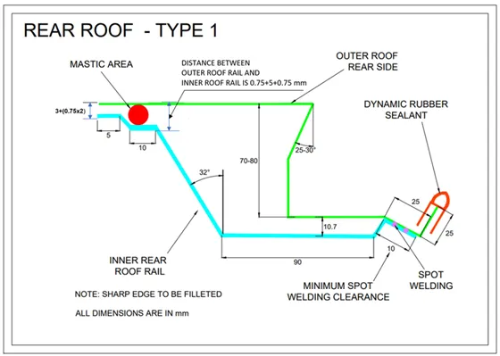
The roof rail is used as the reinforcement to the roof surface at the rear side. The joining method used for this rail is the same as that of the front rail. The minimum radius for the fillet is 3mm. it is also attached with mastic sealants and spot welds.
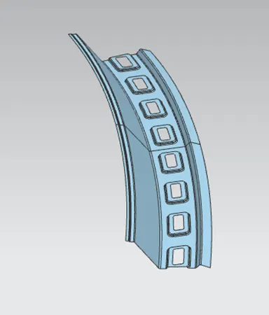
- Joining process-
Mastic and introduce between the roof outer panel and the reinforcement for joining. Where ever the mastic is introduced there is remarkable improve of the strength, spot welding is also introduced to the reinforcement and the outer panel.
- Master section: master section is the pre-defined value of the commodity what we are going to design.
- Roof outer panel & front roof rail-
In the above master section, the vertical flange is given at 7 degree followed by the given class A curvature surface. And the distance between the outer roof panel and inner front roof rail is given 32mm. also the front side ditch area is given 21.50mm in the outer roof and for the inner front roof rail it is reduce by 2.00mm hear at this end there is spot welding is shown so, there is no any gap between edges. In the end of the inner front roof rail is 10.00mm and 5.00mm distance horizontal flange are given where the sealant is used. So area is given for mastic joint is 3.00mm and 5.00m.
The front roof rail is used as the reinforcement to the roof surface to increase the strength and also used to mount the brackets for the same features such as room lamp or map lamp and rear mirror. The depth of the front roof rail is decided based for the driver visibility. The width of the front roof rail is decided in such a way that there should be enough headroom clearance between the head of the driver and the end surface of the roof rail to avoid injuries to the person.
- Bow roof master section-
The overall width of the bow roof should lie between 65-75mm and all the embosses have at least 7 degree of positive draft with respect to the tooling direction. Then the offset of the bow roof outer flange is 0.75+5+0.75mm for the roof outer panel because of the mastic area.
- Center roof master section –
The all parameter like the bow roof, the overall width of the center roof should be lie between 80-90mm and all the emboss have at least 7-degree positive draft wit respect to the tooling direction. Then the offset of center roof outer flange is 0.75+5+0.75mm from the roof outer panel because of the mastic area.
- Rear roof rail-
The outer roof panel rear flange should have the negative flange 0f 25 to 30degree draft to accommodate the clearance for the back-door movement the overall Hight of the rear flange must lie between 70-80mm. the dimension for the roof rail are offset of (0.75+3+0.75) & (0.75+5+0.75) for front flange, which is given because of mastic area. And the 10.7mm for the offset of the center emboss and its width is 90mm. then the draft angle for emboss connecting the front flange is 32degree, here is the rear area of thee rear roof rail is spot welding to the outer roof so there is no gap maintain between them at this are because of the spot welding.
- Design consideration for a roof-
- Visibility criteria
- Head clearance
- Heat distortion
- Snow load criteria
- Draft analysis
- Roof Crush Test-
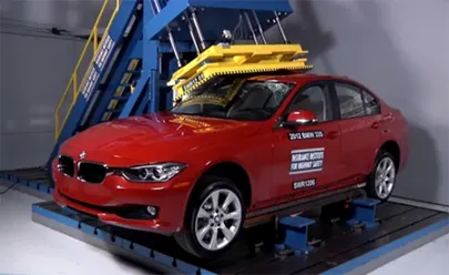
Roof crush test is the design given by the IIHS (insurance institute of highway safety). After analyzing the many accidents IIHS has then fixed some regulation, that how to perform the crush test.
IIHS gives the rating based up on this test. For this they consider two points while giving the rating. How fast the car can reform to its original shape after the roll over and how deep is the protrusion after the roll over.
- Goal of roof crush test-
To minimize the protrusion into the occupant compartment, so that the seat belt and air bags can do their important job in protecting the occupant.
- Condition to follow for the roof crush test:
There are two condition that should be followed for the roof crush test that are-
- Initial condition-
- Close and lock all the door
- Close all the window
- Second condition-
Fix the body sill or chassis frame on a hard lever surface horizontally.
- Method of applying the force-
The load is applied in such a way that 5 degree is tilted from the front end to the rear end and the load will be in 800mm in length and 750 mm width. The load is applied at the position of 25degree from the flatness of the roof. The load is applied on the roof for almost 120 sec and the crush speed at which the load applied is 13mm/sec of less than that.
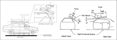
- Result-
If the displacement goes above the requirement level than we have to increase the bow roof thickness or add more mastics points to increase the strength. The stronger the roof the better it can protect the occupant in the roll over crash.
- Calculations-
- Heat distortion curvature study-
This study is used to find out and predict the heat distortion temperature at where the material starts to soften when exposed to a fixed load. So, in order to avoid bending or damage of the roof based on this calculation we will decide the position on the roof bows on the roof.
Bow – roof prediction formula
W= [1.73 × 10^ (-3) × L] + [ 1.85 × 10^ (-8) × (R^2)/t] + [ 1.10 × 10^ (-3) × l] -2.68
Judgement condition: ok <2.7>3.1
Where
- L= Roof length in X-direction[mm] (roof dimension in 0-Y)
- R= Roof curvature
- R= 2(RX×RY)/ (RX+RY)
- RX= X curvature
- RY= Y curvature
- t= roof plate thickness
- l= bow roof span[mm]
- Judgement condition: OK< 2.7 > 3.1
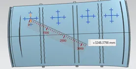
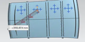
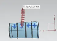
- Thickness for the roof-
- Roof outer panel, t= 0.75mm
- Front roof rail, t= 0.75mm
- Rear roof rail, t= 0.75mm
- Bow roof rail front, t= 0.75mm
- Bow roof rail rear, t= 0.75mm
- Reinforcement roof rail, t= 0.75mm
- Result-
|
Bow position |
RX |
RY |
o R [R= 2(RX×RY)/ (RX+RY)]
|
l |
L |
t(mm) |
R2/t |
W |
OK/NG |
|
FR and 1st bow |
3897 |
2442 |
3002 |
321 |
2028 |
0.75 |
12016005 |
1.40 |
ok |
|
1st and center |
4053 |
3808 |
3926 |
356 |
2028 |
0.75 |
20551301 |
1.600 |
ok |
|
Center and 2nd |
3956 |
9742 |
5627 |
509 |
2028 |
0.75 |
42217505 |
2.17 |
ok |
|
2nd and RR |
3248 |
14145 |
5282 |
303 |
2028 |
0.75 |
37199365 |
1.84 |
ok |
- The model has passed the heat distortion criteria.
Judgement condition- OK<2.7
- Procedure
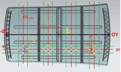
- We create a 0Y line on the top of the roof.
- We sketch a -3Y which is 300mm below from 0Y line.
- We sketch 2 line both side of -3Y line at 100mm distance
- We sketch a line in the middle of the FR and bow roof 1, bow roof 1 and center, center and bow rood 2, bow roof 2 and RR.
- We sketch 2 line on the both sides of the middle line.
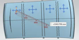
- We create intersection points of the line and project it on the roof then measure the RX and RY
From the above table we, conclude that all the values are of W<2.7. which is fulfill the judgement condition. So, that all bow roofs areas are placed at the right place. This shows the design is safe in heat distortion criteria.
- Snow load prediction formula-
This calculation is done to check the strength of the roof with snow load. In some country snow falls happens so for that reason this calculation is necessary, if the roof will fail in this calculation we create emboss on the roof to provide the strength.
QR= [iy ×t2] / {a × s × [(RX+RY)/2}2 ×10-8}
Where-
a= My× LX2 × 10-12
My = Y(Ly-y)
LY= distance between the front and rear roof rails on the vehicle along with 0Y(mm)
Length of the roof panel with the center point between roof rail front / rear as the front and rear reference point.
LX= distance between the left and right end of the roof on the roof bow (mm)
The width of the roof panel is exposed on the surface.
Y= distance from front roof rail to roof bow (mm).
S= distance for which roof bow bears divided load(mm).
S= L1/2 +L2/2
iy= geometrical moment of inertia of roof bow (Y cross-section) (mm4)
RX= Lateral distance curvature radius of roof panel Y cross- section on roof bow (mm)
Roof panel curvature radius of the length LX in front view.
RY= longitudinal direction curvature radius of the roof panel X cross-section on roof bow(mm)
Roof panel X curvature radius of length s in side view.
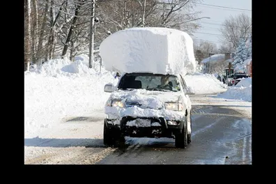
Judgment condition – Qr ≥ 3.1
- We create 2 line on the both side of 0Y line at 100mm distance
- We create a middle line in between FR and bow roof 1, bow roof 1 and center, center and bow roof 2, bow roof 2 and RR.
- We create 2 line on the both sides of these middle lines at 100mm distance
- We create intersection points of the line and project it on the roof then measure the RX and RY distance.
- Qr ≥ 3.1
- 250 ≤ s ≤ 380
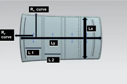

Rx and Ry -
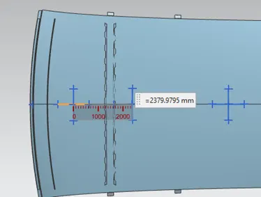
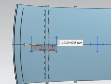
|
Roof rails |
Iy |
Lx(mm) |
Ly(mm) |
L1(mm) |
Rx |
Ry |
t(mm) |
S(mm) |
My(mm) |
((Rx+Ry)/2)^2) |
α |
Qr |
Results |
|
front - 1 bow roof |
1149 |
113.5 |
2028 |
501 |
4685 |
2380 |
0.75 |
511.2 |
76296.17 |
7713840 |
0.993263 |
16.5 |
ok |
|
frist - center roof |
1109 |
1084 |
2028 |
500 |
4971 |
2510 |
0.75 |
510.5 |
786447.6 |
12473823 |
0.24785 |
10.59 |
ok |
|
center to 2 bow |
2342 |
105.5 |
2028 |
441 |
4249 |
3018 |
0.75 |
470.6 |
766055.5 |
43724639 |
0.855653 |
6.484 |
ok |
It is observed from the value that not obtained values of Qr >3.1
- Moment of inertia-
- Y=I/Y
- Where
- Section modulus(mm^4)
- I = moment of inertia of the section about the bending axis
- Y= distance between the neutral axis and extreme end of the object(mm)
- Moment of inertia for front roof rail-
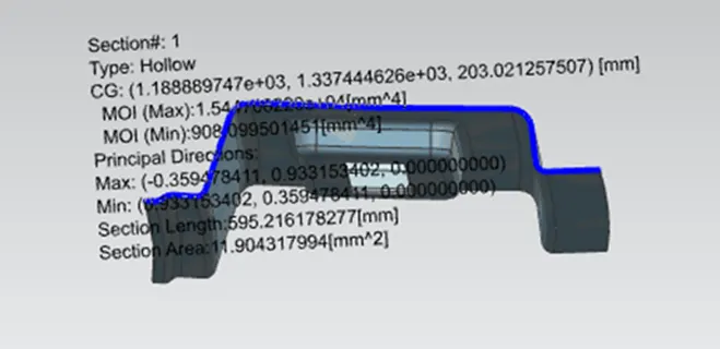
Moment of inertia (MOI), max= 8.836287812×10^4(mm^4)
- Moment of inertia (MOI), min=5.671644013×10^3(mm^4)
- Distance between the natural axis=120/2mm
- =60mm
- S=I/Y
- Section modulus(max) S=836287812×10^4(mm^4)/60mm
- =1472.7146(mm^3)
- Section modulus(min) S= min=5.671644013×10^3(mm^4)/60mm
=94.5274(mm^3)
- Moment of inertia for 1 roof rail-
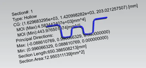
- Moment of inertia (MOI), max= 4.583442407×10^3(mm^4)
- Moment of inertia (MOI), min=976501474(mm^4)
- Distance between the natural axis=70/2mm
- =35mm
- S=I/Y
- Section modulus(max)=583442407×10(mm^4) ^3/35mm
- =130(mm^3)
- Section modulus(min) S=976501474(mm^4)/35mm
- =12.68504289926(mm^3)
- Moment of inertia for center roof rail-
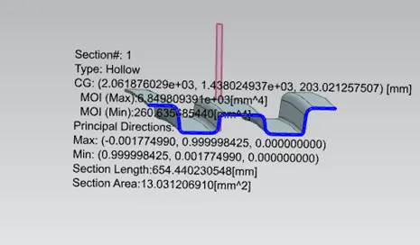
- Moment of inertia (MOI), max= 6.849809391×10^3(mm^4)
- Moment of inertia (MOI), min=260.635685440(mm^4)
- Distance between the natural axis=80/2mm
- =40mm
- S=I/Y
- Section modulus(max) S=849809391×10^3(mm^4)/40mm
- =163.452(mm^3)
- Section modulus(min) S= = min=260.635685440(mm^4)/40mm
=6.515892136mmˆ3
- Moment of inertia for bow roof 2-
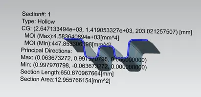
- Moment of inertia (MOI), max= 4.58364089×10^3(mm^4)
- Moment of inertia (MOI), min=447.85330638(mm^4)
- Distance between the natural axis(Y)=80/2mm
- =40mm
S=I/Y
- Section modulus(max) S= 4.58364089×10^3(mm^4)/40mm
- =114.510(mm^3)
- Section modulus(min) S= min=447.85330638 (mm^4)/40mm
- =11.1963(mm^3)
- Moment of inertia for rear roof rail=
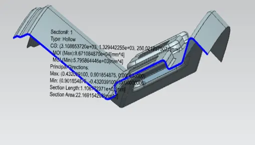
MOI (min)=5.795864446×10^3
MOI (max)=8.671084870×10^4
Draft analysis-
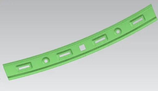
- Draft analysis for front roof rail.
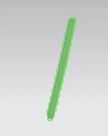
- Draft analysis for 1 bow roof rail-
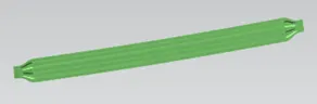
- Draft analysis for center roof rail-
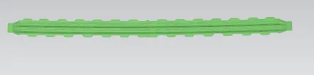
- Draft analysis for bow roof 2-
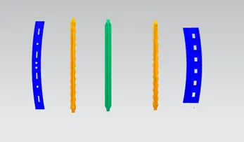
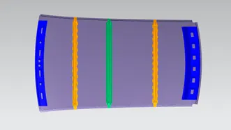
- Roof complete design-
Conclusion-
I have completed the roof design, roof rail and bows for better support and strength.
We design it so as to satisfy the norm and regulations by calculating the heat distortion criteria and snow load criteria. And also studied about methodology behind the roof designing the roof of the car.