Week 9 - Challenge 3 - Bumper
AIM- To create a bod of Bumper from the input given which is the A-surface of bumper. the cretaed body should be a closed voulme be feasible for manufacturing and tooling.The draft angle and draft analysis of the component should be done.
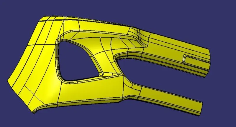
INPUT GIVEN-
- A-SURFCE
- THICKNESS OF COMPONENT IS 3MM
- DRAFT ANGLE IS 3deegree
CHECKING THE INPUT(A-SURFCE)-
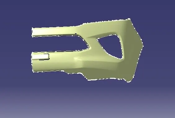
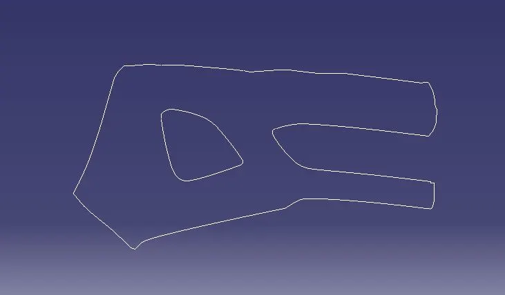
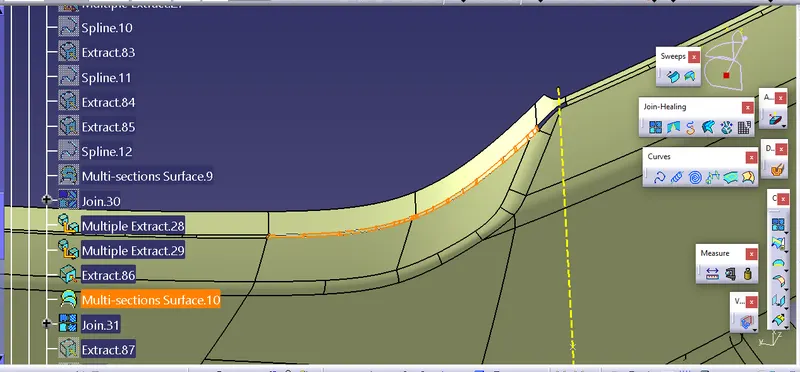
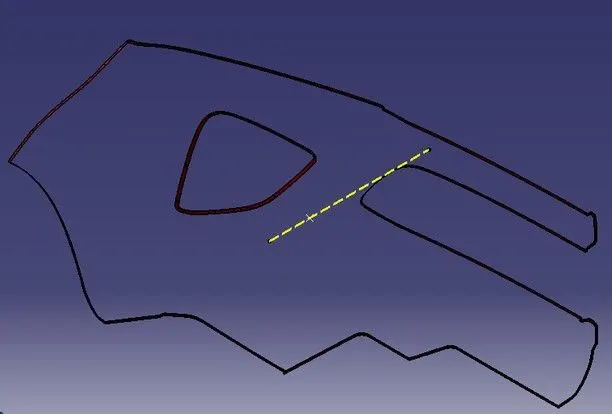
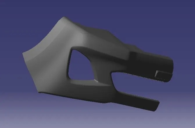
The A-Surface or the styling surfce is frist checked for any gap and other surface issue. This surfce acts as the input surface so any correction to be done should be with approval from the styling team or done by them . A-perfect is the one when a boundary is created, the lines are only on the edges of a component and its holes or cutouts as shown-
CREATION OF TOOLING AXIS-
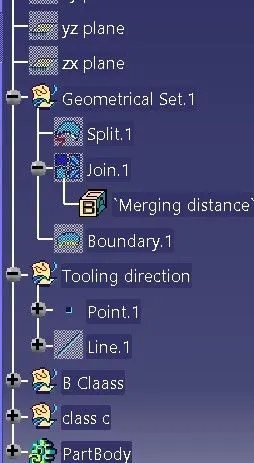
Tooling axis is the direction in which a core or cavity of mold open. the axis is very important to determine the orientation of the component in mold, core and cavity design.
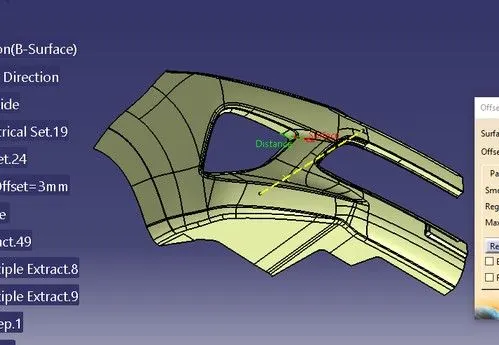
the tooling axis is created by the inertia method by using the steps as follow
- Click "Measure inertia" and select the A-surface.
- Click "Create geometry" in the measure inertia window
- In the creation of geometry window, select Non-Associaticve geometry.
- click "Center of gravity"
- The inertia point is created.
DRAFT ANALYSIS-
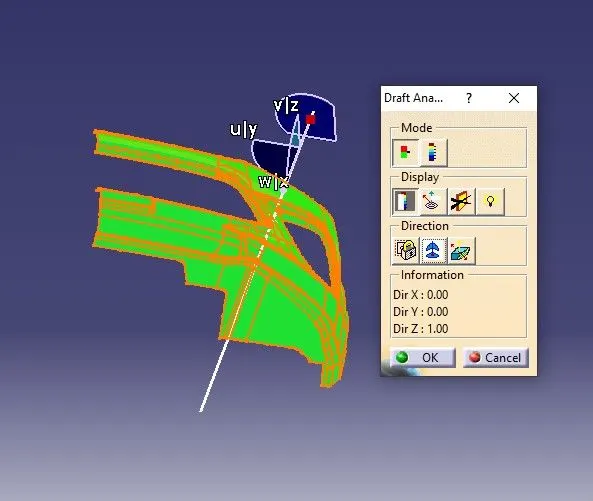
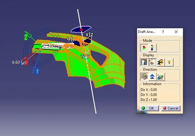
Draft analysis of the surface is carried to check if the surface or part can be manufactured with the required draft angle.
Draft angle is needed for the component to clear the core and cavity surface as it woulde have shrunk towards the center while cooling. the draft angle in this design is 3degree. as a surface is a single surface there will be much difference in color . the draft analysis of A-surface is shown below.
CREATION OF B-SURFACE-
The A-surfce is Offseted by 3mm as it is the thicknes required. the offset surface is the B-surface but had some issues like some areas shown in below images -
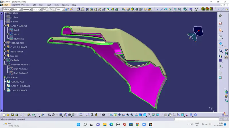
the area where the B-Srface has issue are corrected by closing them using command like multi section, sweep, offset and extract.
finally all creaated surface are trimmed togther with offset surface done earlier. this created a single single surafce which act as the finaal B-Surface.
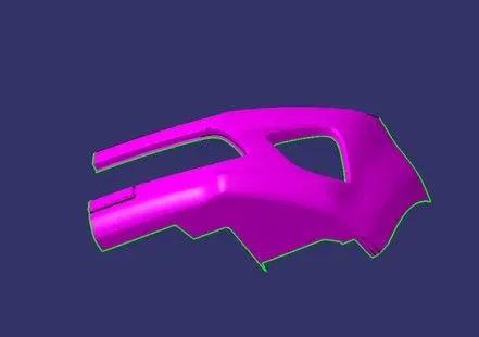
CREATION OF C=SURFACE-
The A-Surface and B-surface connect by the help of c-surface. C-Surface connect the A and B-Surface. it is created bu using sweep command with A-Surface acting as the refrence surface and curve created from the boundry of the same surface. sweep with draft direction is also used to create A-Surface.
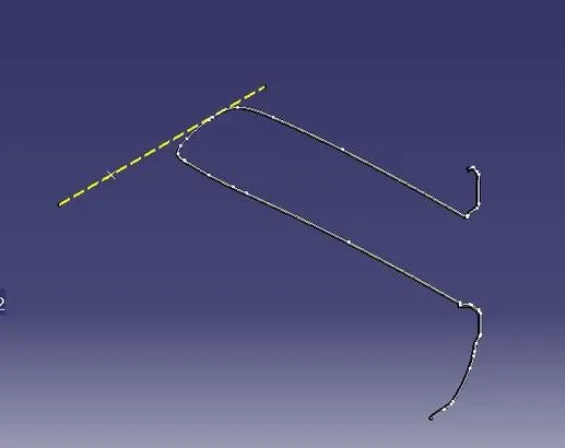
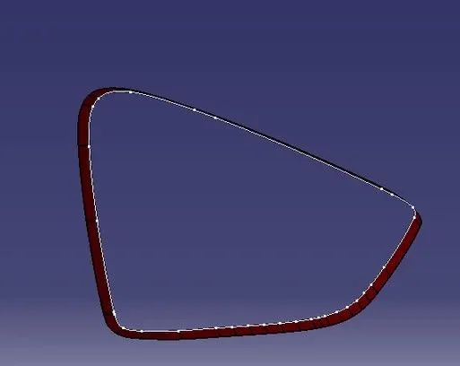
CREATION OD CLOSE BODY-
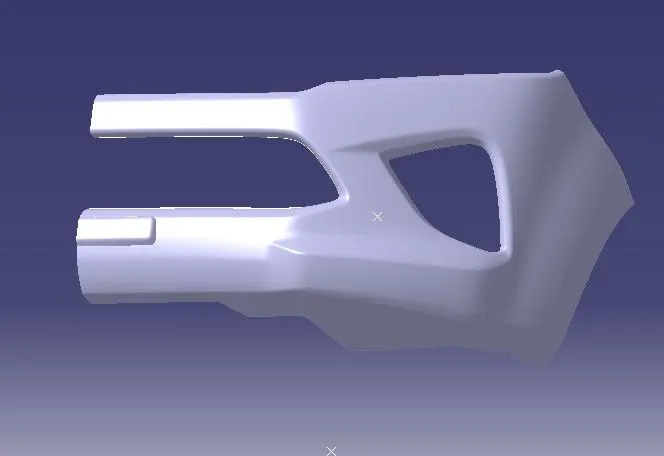
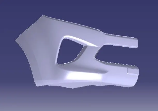
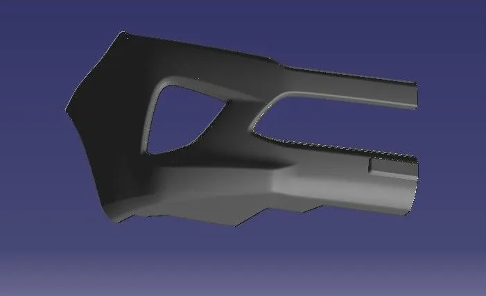
All the surface A,B,C are joined together to from the close body.boundary is selected and the body is picked.
finally in part design workbanch using close voulnme it is changed to a solid body.
PLASTIC MATERIAL APPLIED-
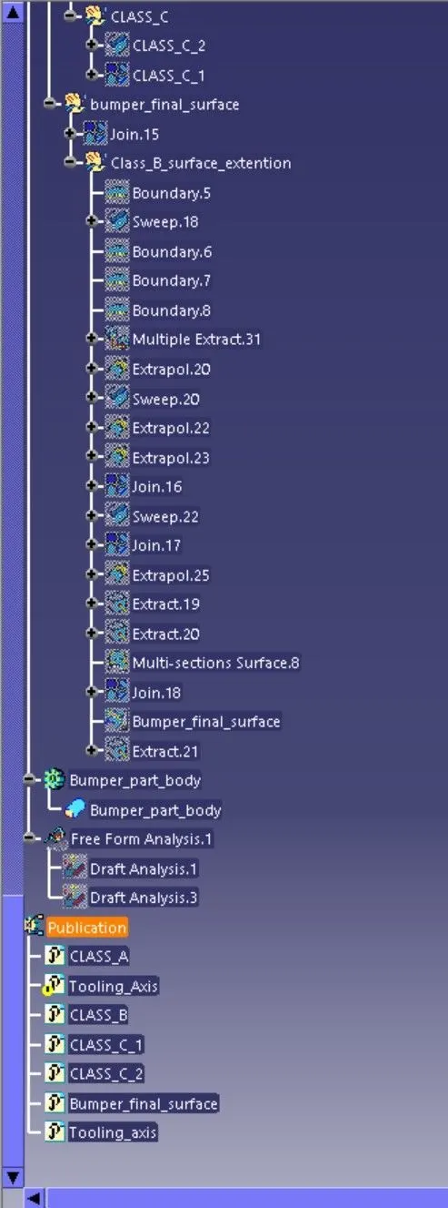
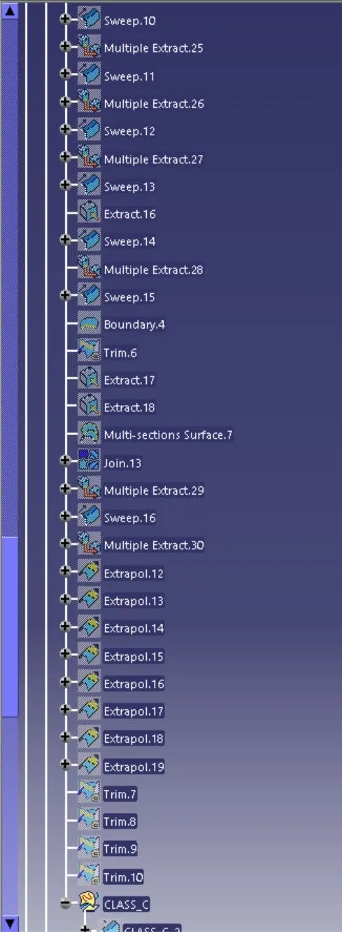
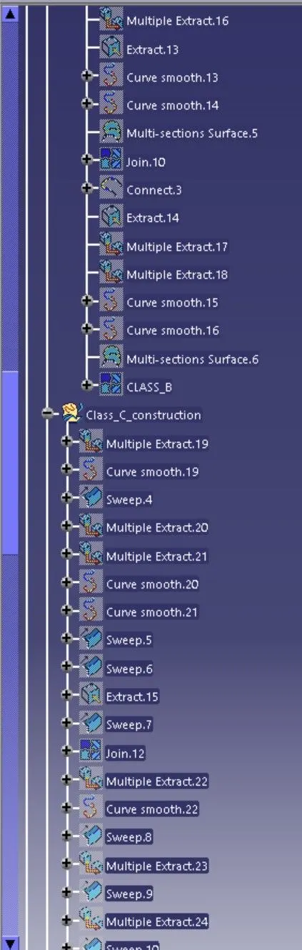
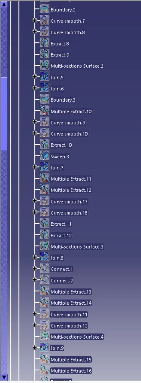
MODEL TREE-