Project 2
HARNESS ROUTING AND FLATTENING ON THE BACKDOOR OF A CAR
Aim
To route the Wiring harness on Given car body and Prepare flatten view drawing in CATIA V5.
OBJECTIVE
- To create the wiring harness routing for the given Car body by using appropriate connectors, clips and clamps which is required.
- To create a flatten view drawing file in Catia v5.
- Need to apply the protection covering like cot tubes and insulation tapes to the bundles as required.
- Need to apply the industry best packaging rules and best practices studied in this course.
Introduction:
In the automotive industry, electrical wiring harnesses are used to provide power and communication between different electrical components in a vehicle. A wiring harness is essentially a bundle of wires, connectors, and other components that are organized and secured together to transmit electrical signals from one location to another.CATIA is a software tool that can be used to design electrical wiring harnesses for car back doors. It provides a range of tools and features to create accurate and detailed harness designs.Using the harness design tools in CATIA, users can create the wiring harness design along the defined routing path. They can select wires, terminals, and other components and arrange them as necessary. The harness design can be adjusted and modified to ensure that it fits and functions properly.
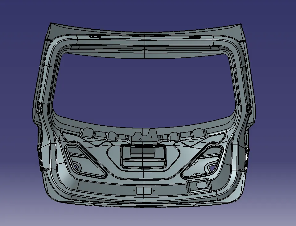
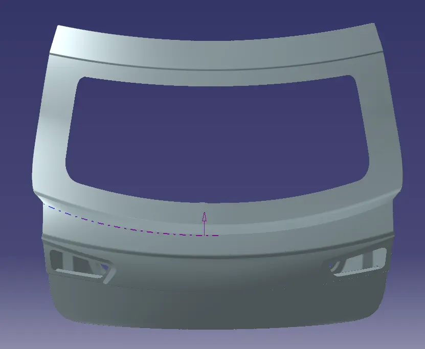
A wiring harness routing structure includes a wiring harness routing member configured to be attached to a vehicle body and a protector that accommodates and holds a wiring harness. The protector has a recess shape in which the protector is opened in one direction in a sectional view. At least one of the wiring harness routing members and the protector includes a fixing mechanism that fixes the protector to the wiring harness routing member. The protector and the wiring harness routing member are configured to be integrated via the fixing mechanism.
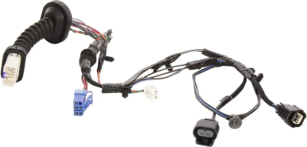
Step : Define the mechanical components and convert them into electrical parts and prepare the catalogue for the same:
- Imported the STP file of the connector into Catia V5 and saved as a CATPART file.
- Switched to part design workbench and created points at the front face and mating face of the connector.
- Switched to electrical part design workbench and defined the connector electrically by using the command 'define connector'.
- And also created the bundle connection point, connector connection point and the cavity connection point of the connector. And saved the connector file into the catalogue which is already created and saved into the device.
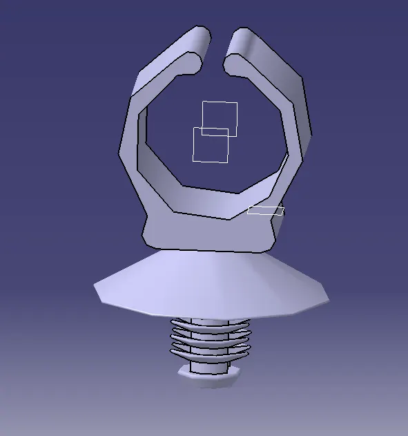
2.1. Defining Fir tree clip of 10mm ,8mm 5mm and adding them to catalogue created
- Import the STP file of fir tree clip rounded into the Catia V5 and save as a CATPART file.
- Now switch to part design workbench and create entry point and exit point for the clip by using the point command.
- Then create the entry plane, exit plane, and base for the clip.
- Now switch to the electrical part design workbench and define the clip by using the command define support part.
- Now define the first point, first plane, second plane and base plane of the clip.
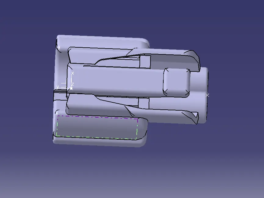
DT06-4S - Two 4 pole connectors for Brake lights.
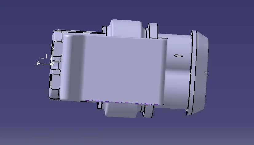
4 pole connector: C-1563689-1
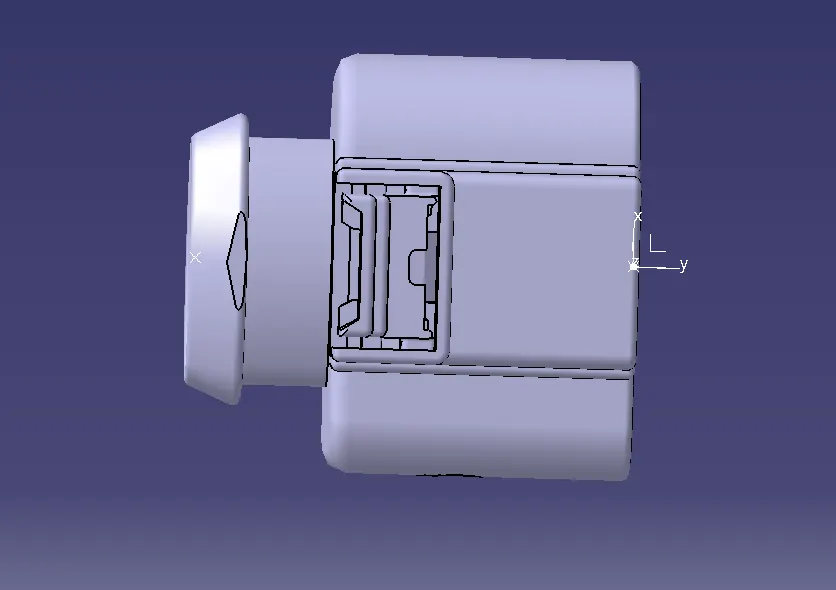
DT06-2S - Two 2 pole connectors for Number plate lights.
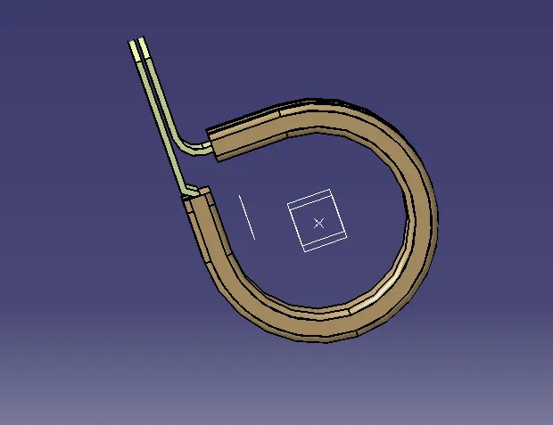
CLAMP
- Fir tree clip of 10mm
- 776438-1 12 pole Inter connector
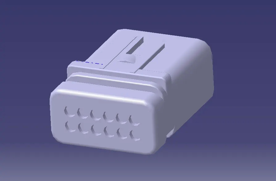
Create a new product file for the wiring harness assembly context, adding the relevant components to each product file and convert the geometrical bundle assembly file into an electrical bundle
- The main product file for the wiring harness assembly context is opened and then add new product file for geometrical bundle assembly under it.
- Open the geometrical bundle assembly in a new window and switch to the mechanical assembly workbench and add all the relevant connectors, fir tree clips, etc required for the harness assembly routing.
- Position the connectors and other components to the desired location by using various commands available in the mechanical assembly workbench.
- Switch to the electrical harness assembly workbench and activate the geometrical bundle command and select the geometrical bundle assembly file from the tree structure then it will convert the geometrical bundle assembly file into an electrical assembly file.
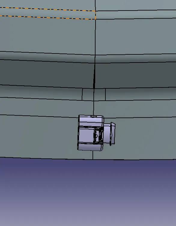
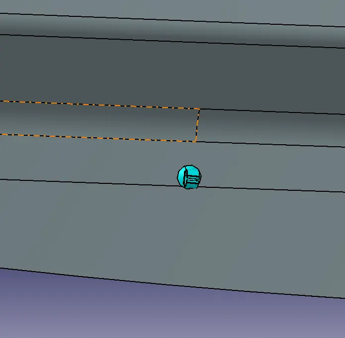
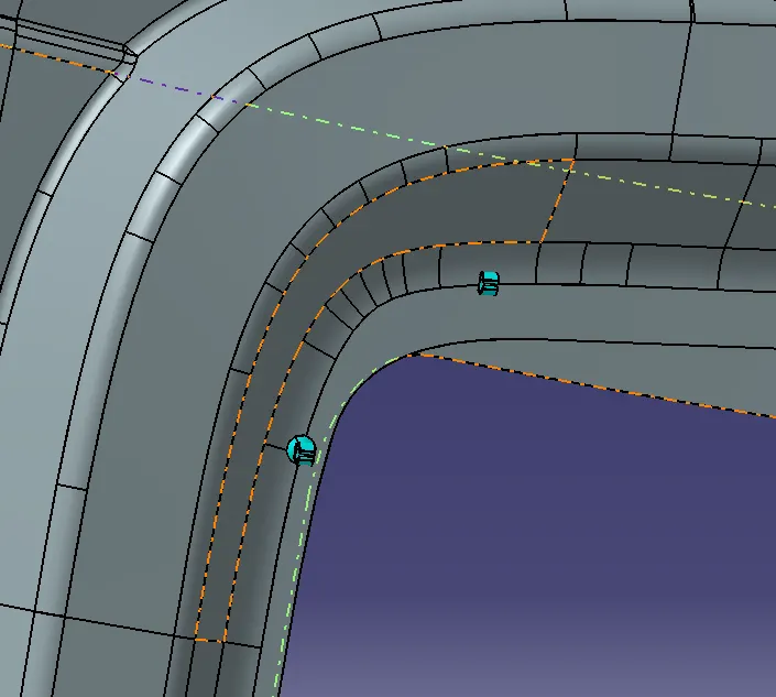
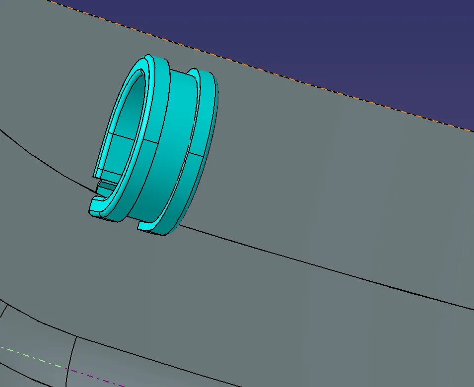
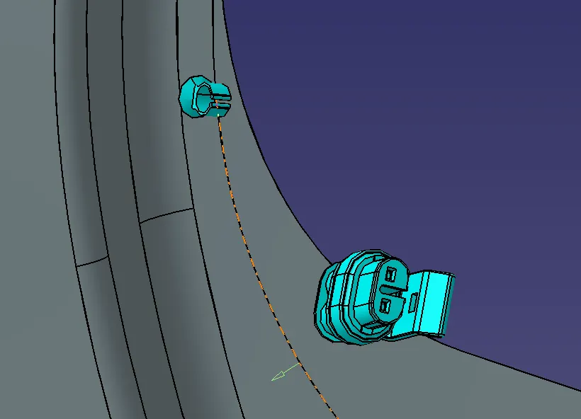
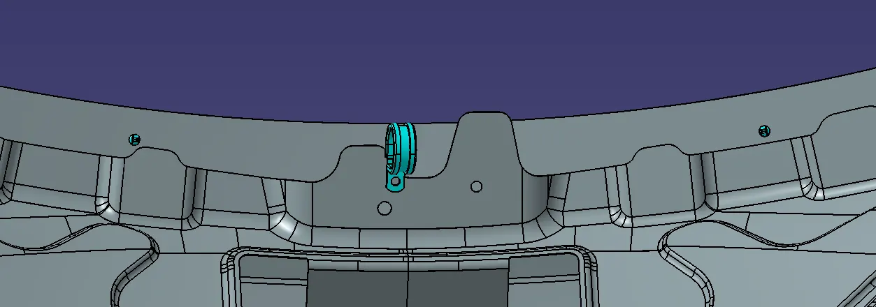
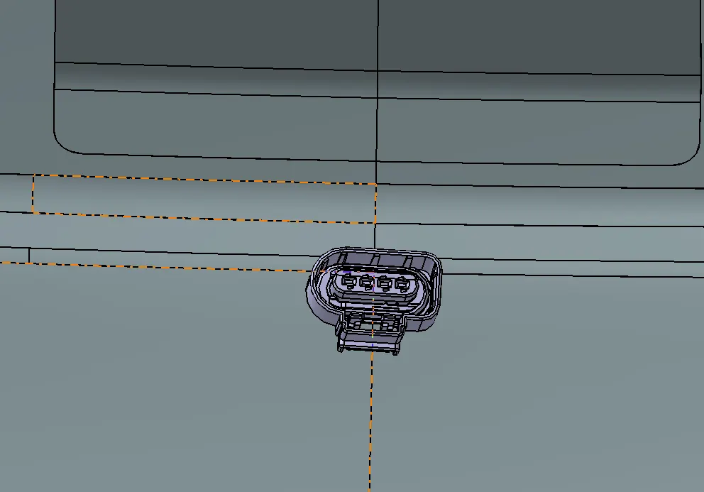
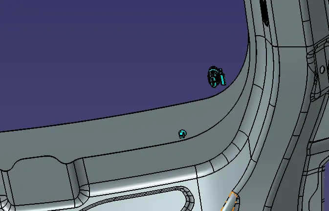
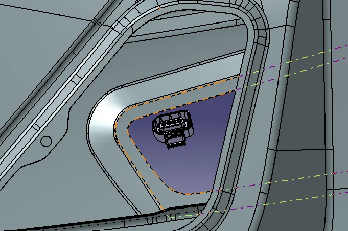
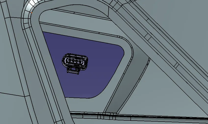
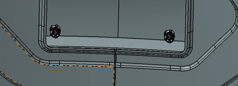
Product file of the backdoor assembly context with geometrical bundle assembly product file and the relevant components for routing
Wiring harness mounting strategy and selection parameters
- Mounting strategy and selection parameters for components, terminals, wire, protection devices, should be strictly followed clearance management while routing
Some of the Harness branching rules are,
- Branch length should be greater than 50mm
- Minimum distance between clamp and nearby branching point should be 25mm.
- Minimum distance between two breakouts should be 25mm.
Routing the wiring harness assembly
- By using the multi-branchable document command available in the electrical harness assembly workbench and adjust the options available likes, connector diameter, bend radius ratio, build mode, and with the help of routing objects options define the routing by adding the desired electrically defined components and adjust the tangency if required to get the proper bundle connection between connectors.
- It is always recommended to use multi-branch routing during the wiring harness assembly.
- We can add branches or split the existing branches by double-clicking the multi-branch-able command then it will automatically switch into the wiring harness installation workbench from there we can add a branch point on the existing bundle to the required position.
- Again go to the multi branch-able document command and select the appropriate electrically defined components and bundles to create sub-branches in the assembly.
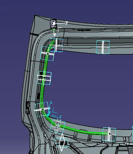
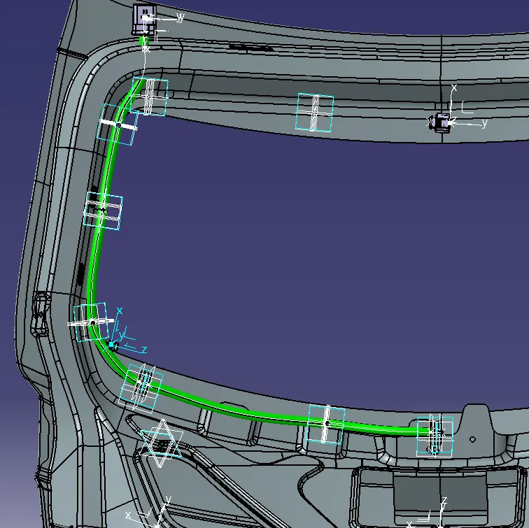
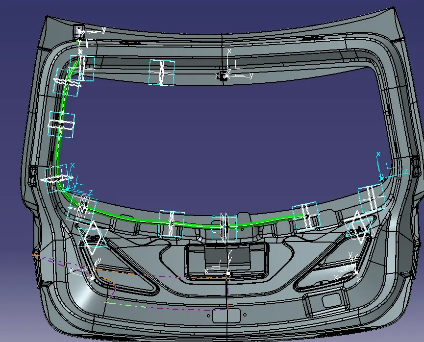
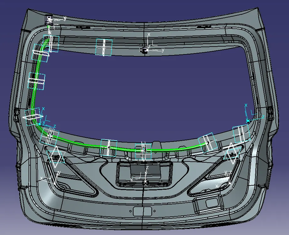
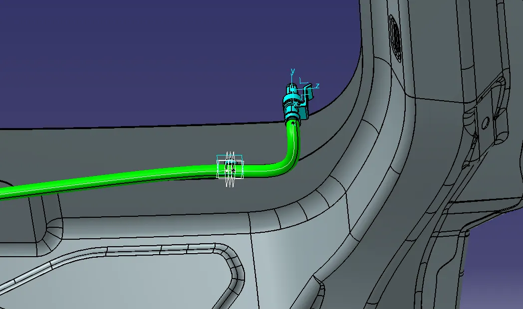
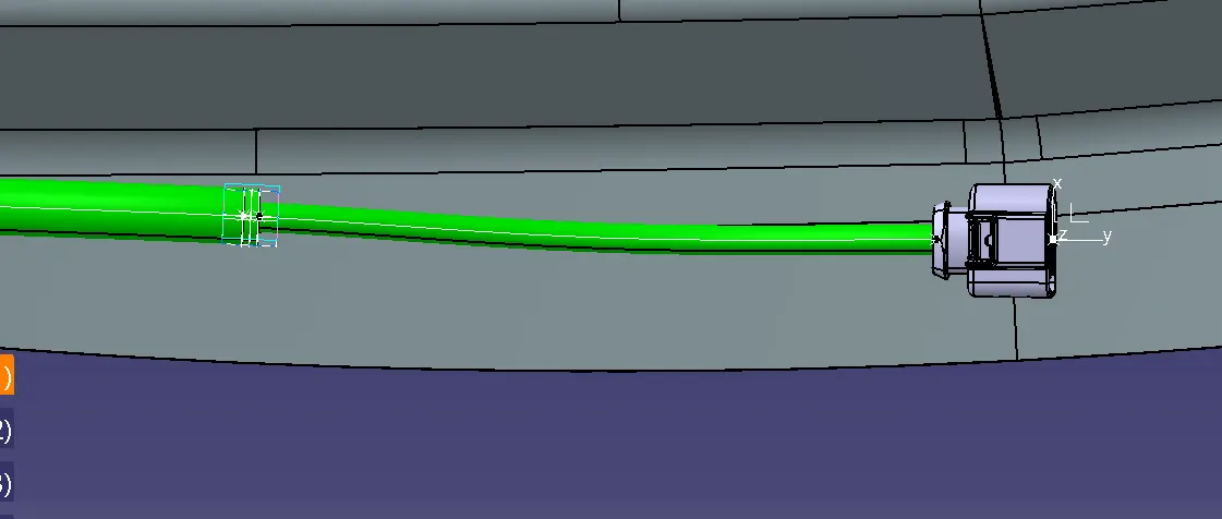
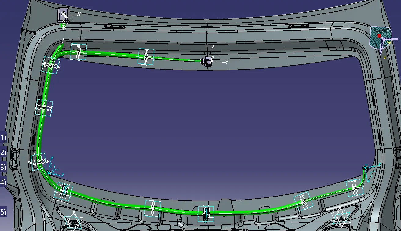
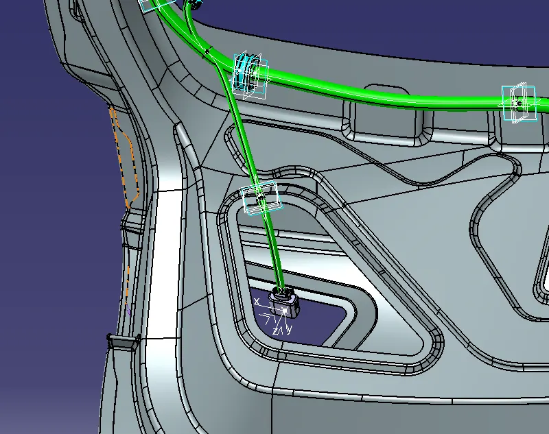
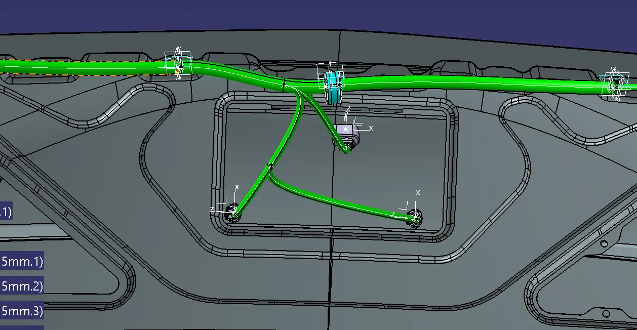
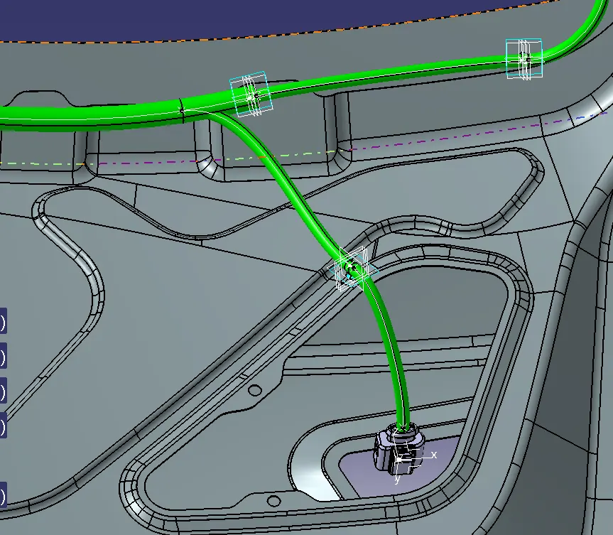
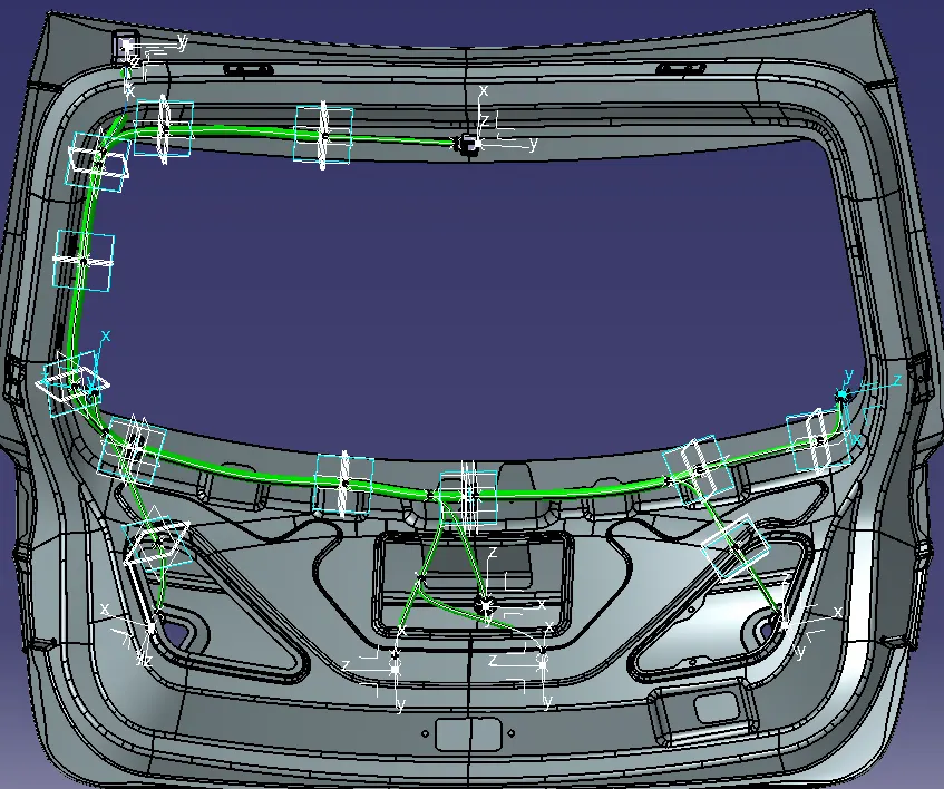
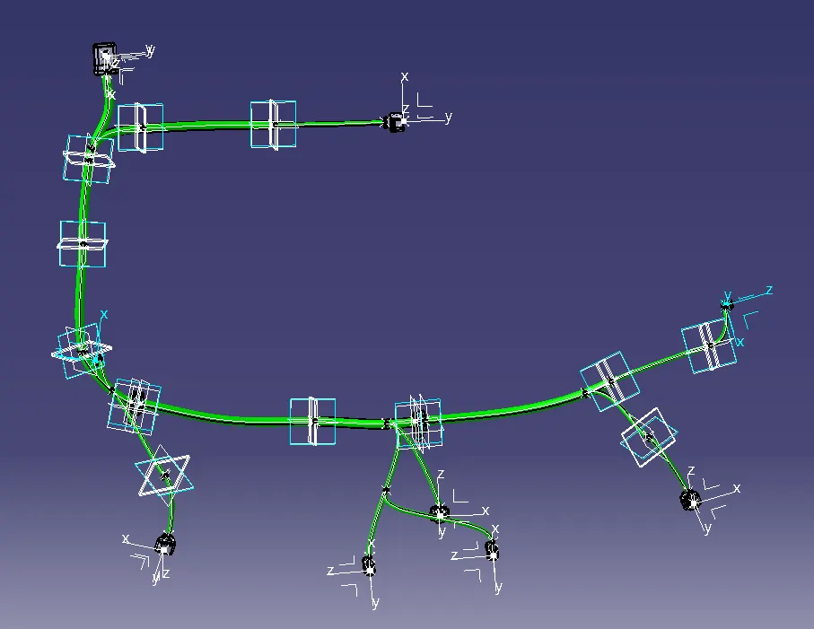
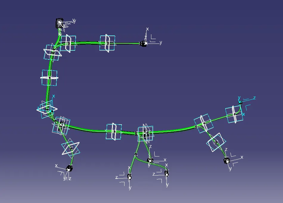
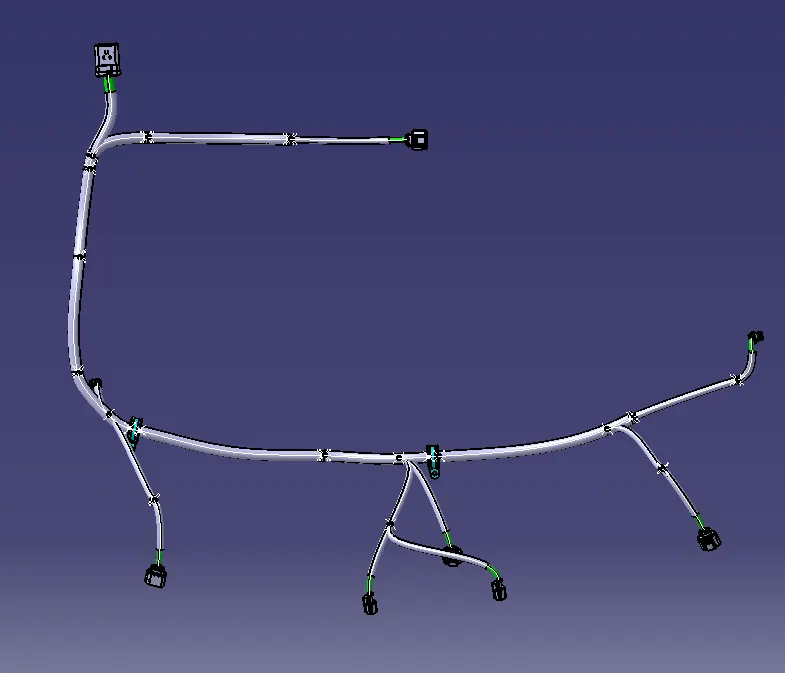
ELECTRICAL HARNESS
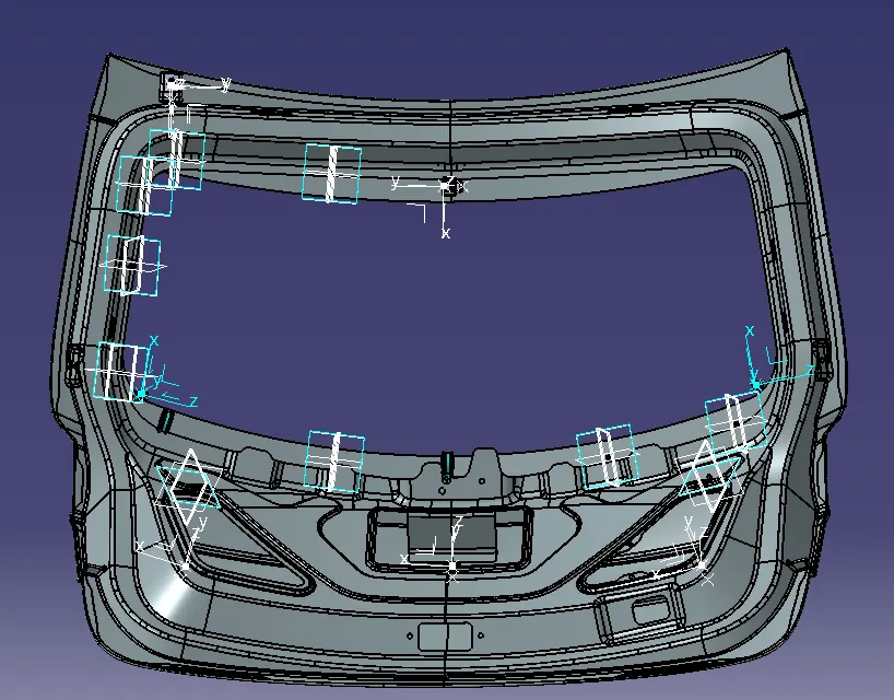
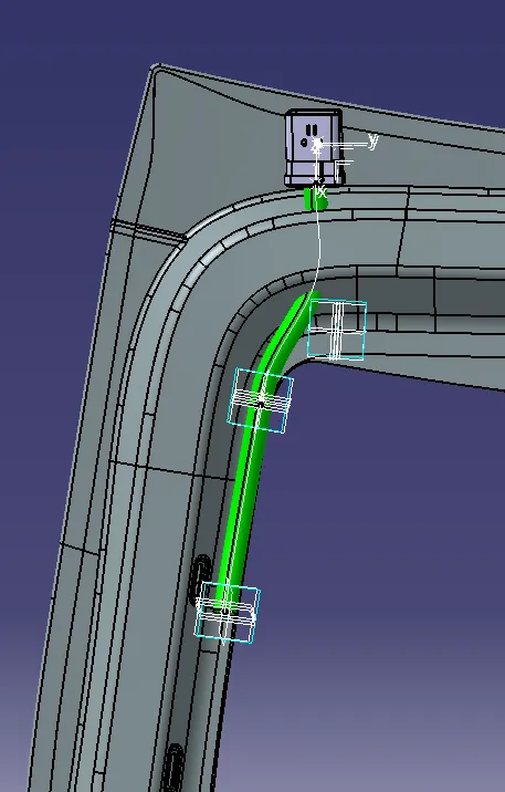
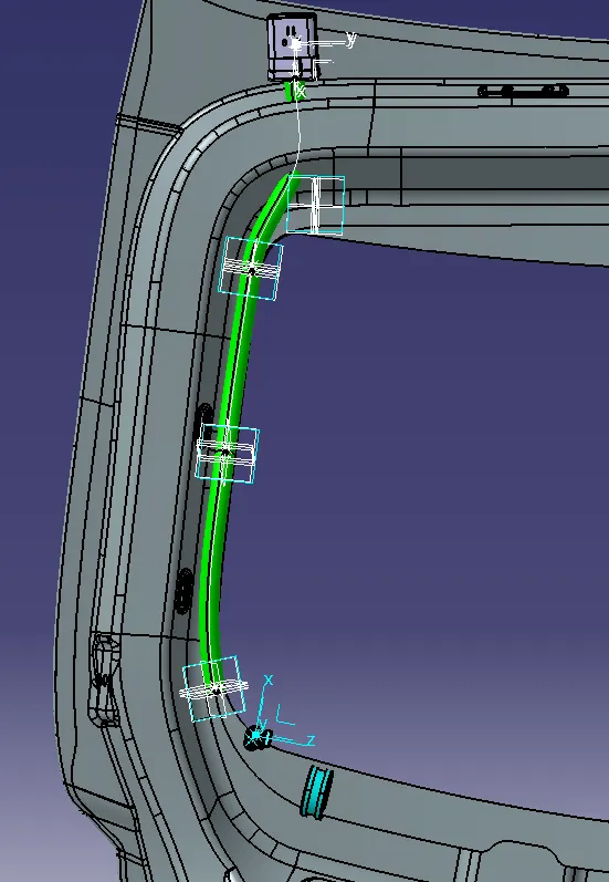
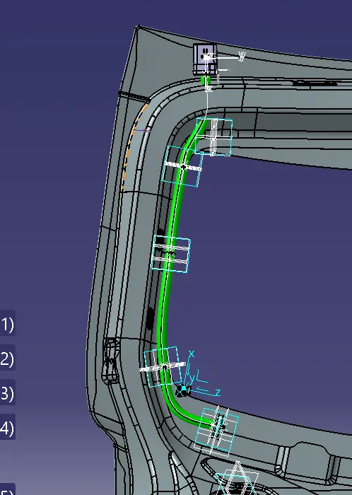
The assembly should have electrically defined connectors and be positioned on the backdoor appropriately.Place the supporting mounting clips in the back door after the connectors are in place to ensure proper routing without entangling the bundle with adjacent components.After completing this route, ensure sure the bundle segment does not collide with the surrounding components.After the geometric bundle is complete, flatten it and check the wiring harness for bundle connectivity.
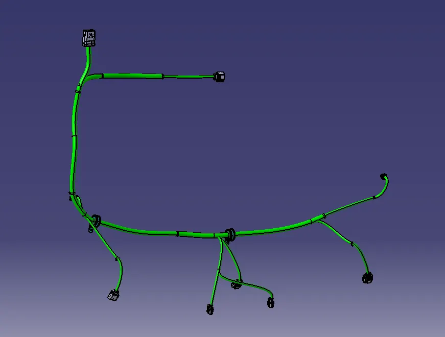
Adding protective covering to the harness bundle
By using protection covering tool we protect all the bundle.we have created a catlouge and we add the protection cover of 15mm diameter and 10 mm diameter.here we Create a gap from the end and start extremity.
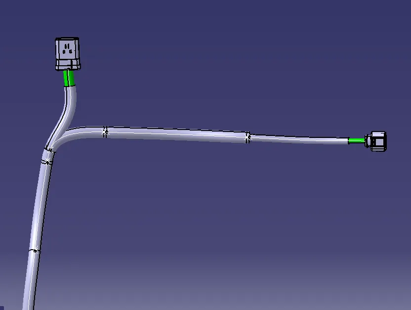
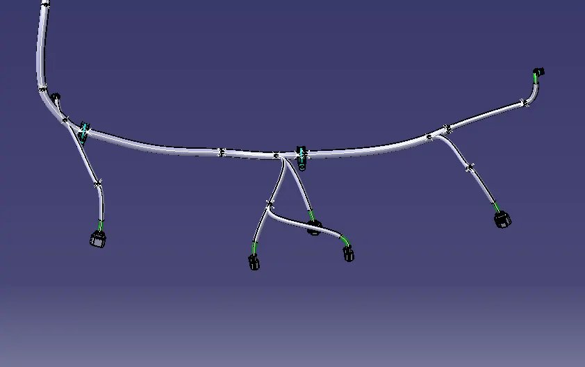
Create flatten view
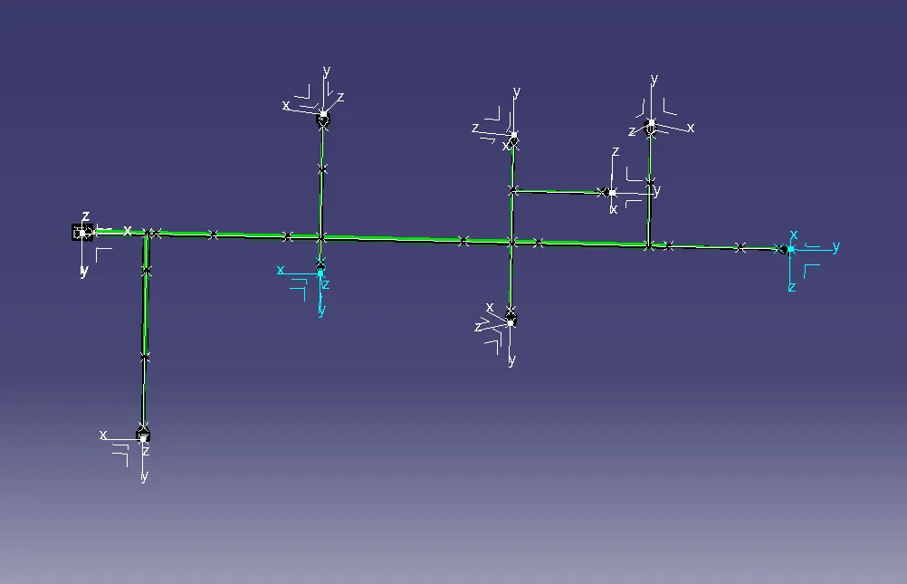
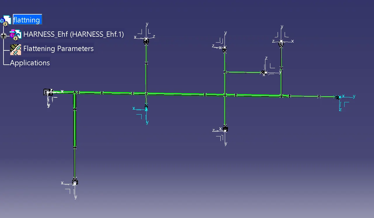
ow we open a new product file for the Electrical harness flattening. Here we save the already made geometrical bundle segment and we extract the geometrical bundle to flatten harness by apply flattening parameters we flatten the geometrical bundle.
Once the branches are flattened we do some modification in the branches using the rotate, bend, and straighten etc. tools in the Electrical harness flattening.
Creating a flatten view drawing-
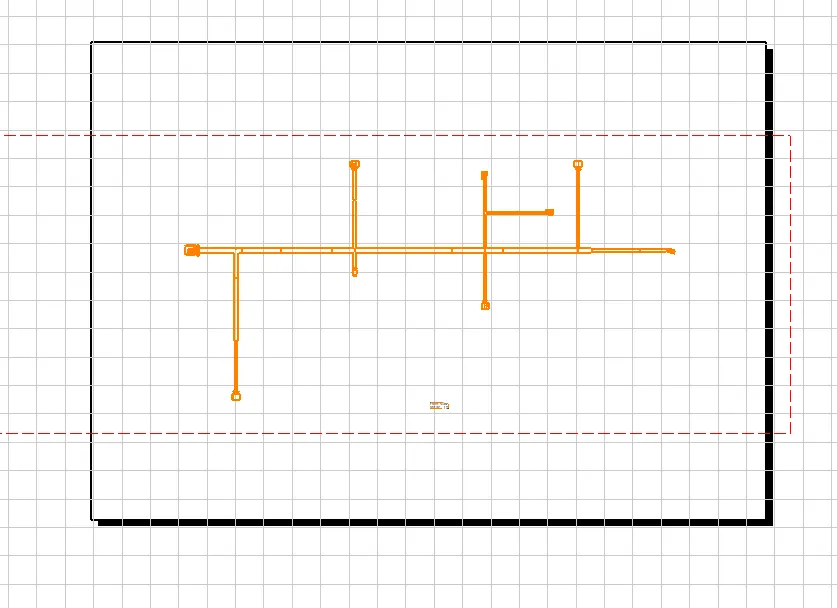
Make a new drawing file and define all the necessary drawing parameters. Insert the front-view of the harness assembly into the drawing file.
Define drawing properties as shown below. It should be noted that for the "dress-up" settings 3D wireframe is always "ON". If this setting is not selected then the bundle segments will not be visible on the drawing view.
Final drawing of the flatten-view of the car body wiring harness assembly with all the mounting clips and mounts.
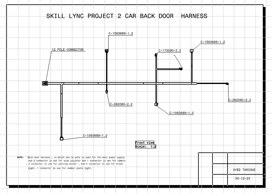
ALL REQUIRED FILE ARE ATTACHED
THANKYOU