Project 1
project-1
Aim:To route the wiring harness of given Engine model and prepare flatten view drawing in CATIA V5. Apply all packaging rules and industry best practices.
INTRODUCTION
A wire Harness , also Commonly referred to as a Wiring Harness , is an exterior Sheet used to cover some types of electronic Wires . Generally, Wiring Harness are made of thermoplastic or thermoset materials that can help protect the cables from the environent.
A cable harness, also known as a wire harness, wiring harness, cable assembly, wiring assembly, or wiring loom, is an assembly of electrical cables or wires which transmit signals or electrical power. The cables are bound together by a durable material such as rubber, vinyl, electrical tape, conduit, a weave of extruded string, or a combination thereof.
Methodology -
Design Criteria for Wiring harness
Wiring harness should be routed in following way that :
- it is easy to assemble on vehicle.
- It is easy to access in case of service or failure analysis.
- It should be secured properly so that it should not get damaged by surrounding component intraction.
- It should be kept away from heat zones like engine exhaust,mufflers,turbo chargers.
- It should be kept away from areas of direct water splashes.
- It should be kept away from sharp environment like sheetmetal bracket edges, corners, panel edges etc.
- It has to ensure human or machine intraction will not cause any dameges to harness.
- It should be kept away from driver or passanger reach zone.
- It should be kept away from High pressure fluid lines.
- Dynamic conditions of the vehicle should not damage the wiring harness.
- Keep harness away from tyre envlope.
- The harness should not be visible or exposed inside the vehicle.
Assumptions-
- Provide clips/clamps as per requirement.
- Make sure that there is no any fauling case while designing the wire harness. Additional clips/clamps may be used to avoid fauling case.
- Give additional slack if needed. 5-10% slack is sufficient.
- Avoid routing over bolt and bolted joints to avoid harness puncture.
- Avoid routing on sharp edges or else provide protection over the harness.
- Follow the clearance distance and keep away the harness from heat generation components.
- Protection should be provided as needed according to surrounding temperature.
- Avoid direct support for harness on fuel lines routed in the engine.
- Use plastic guiding channels if needed.
- Branch length should be greater than 50mm.
- Minimum distance between two branch points should be at least 50mm.
- Minimum distance between clip and branch point should be at least 25mm.
- Avoid too many sheet metal brackets on the engine. Try to use available threaded bosses on the engine or demand for it.
- The wiring harness should be easy to assemble and easy to access.
- While using dummy connectors, ensure that whatever positions you are defining that are practical. Bundle diameters and another placements can be defined properly for the wire harness routing.
- If the packaging area is too tight and there are many packaging constraints then we can think of creating harness channel which can be used to route and protect the wire harness effectively.
Clearance Managment
Procedure -
- Download the Enigne File and all the cad parts for wiring harness(connectors, clips, clamps, channels, brackets)
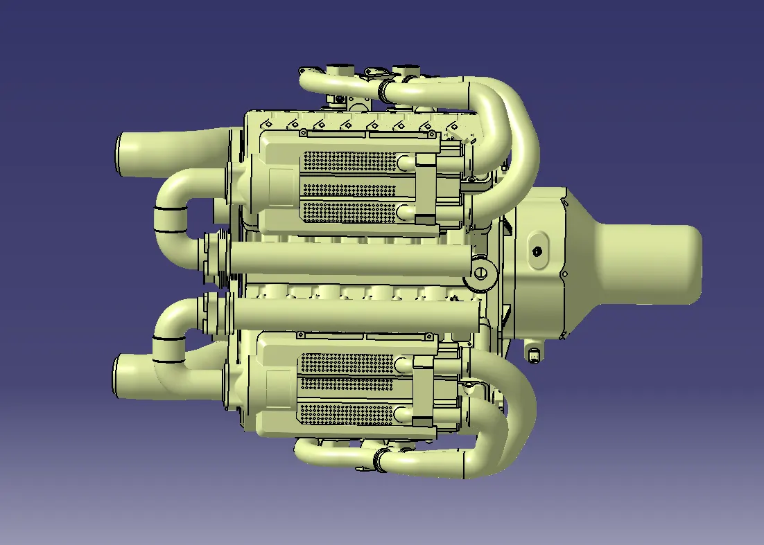
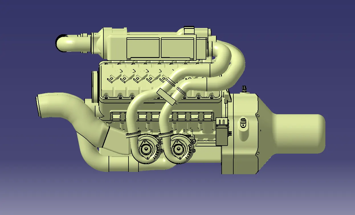
Step - Download and define the plastic channel electrically.
. Procedure for electrically defining the Channel.
. Create bundle entry point and exit point.
. Create a line Curve between the main entry and exit points for creating the multi-branchable using external curve inside the channel.
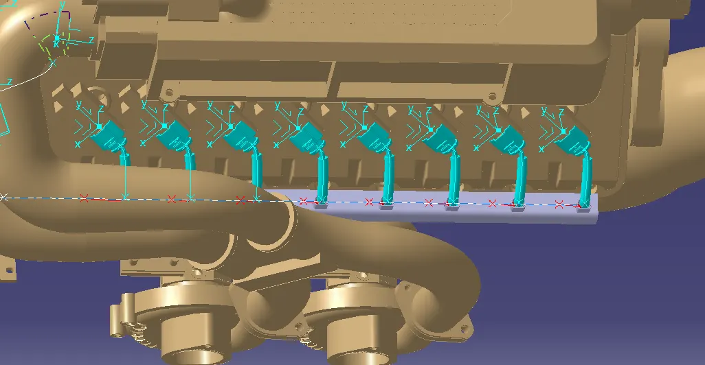
. Create 8 bundle entry points on the openings for connecting the injector connectors.
. Using the geometrical parameters define the channel electrical using the define mounting equipment option.
. Create define bundle entry points using the " define bundle connection point option .
Defining 12 pole connector
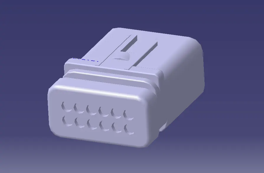
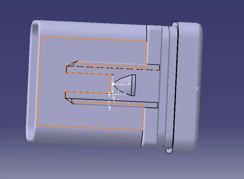
Defining Mounting Clip:
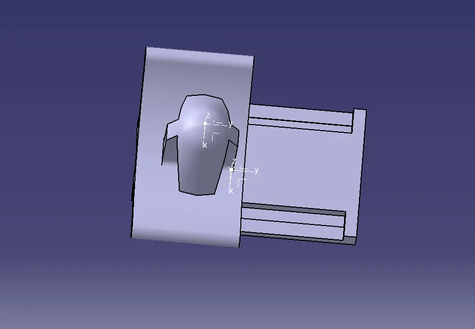
Defining 4 pole connector :
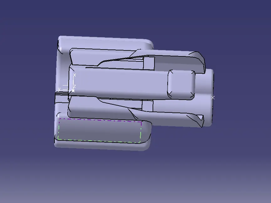
Defining 2 pole connector :
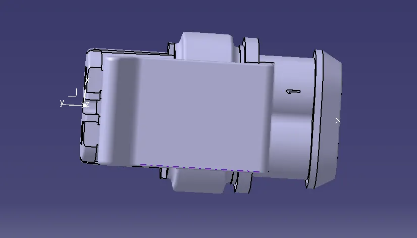
create new Product file for inter Connection Connector and Cavity Assembly.
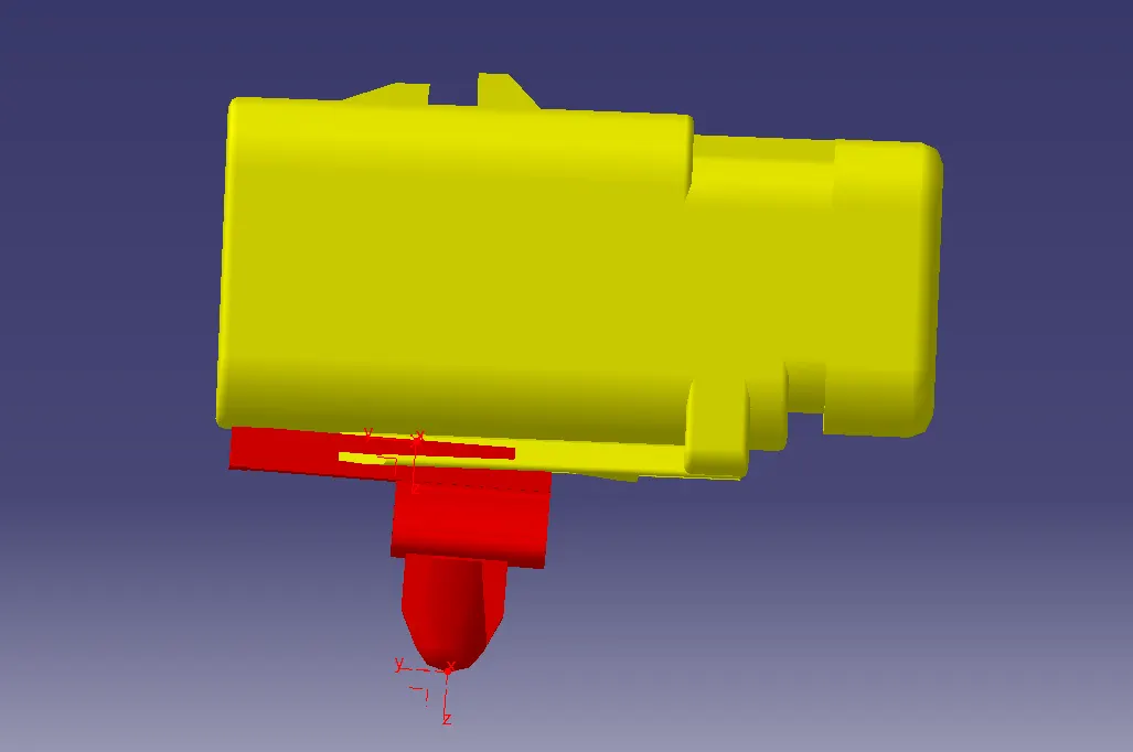
Mounting of a plastic guiding channel
We have to add now plastic guiding channel because Bugatti V16 engine has 8 injectors on right side and 8 injectors on left side which are very close to each other. Hence plastic guiding channel is best option for proper and easy routing of the wiring harness. It will reduce the complex wiring harness routing. We will require two different guiding channel for both right and left side of the engine. Now, before placing guiding channel, we have to define geometrical parameters of guiding channel as below.
- n above figure, we have created point 1 at entry face and another point at endpoint at 560mm distance.
- Now, join that both points and create a line which will be later used for routing the wire harness bundle inside the guiding channel.
- Above figure shows for the left side guiding channel and same process will be repeated for the right side channel.
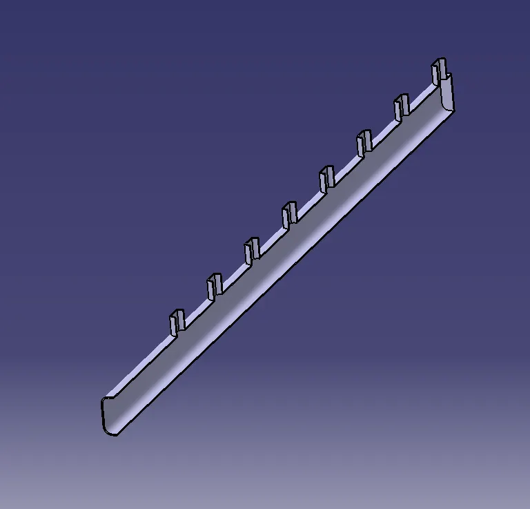
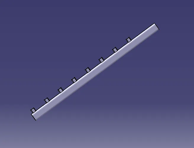
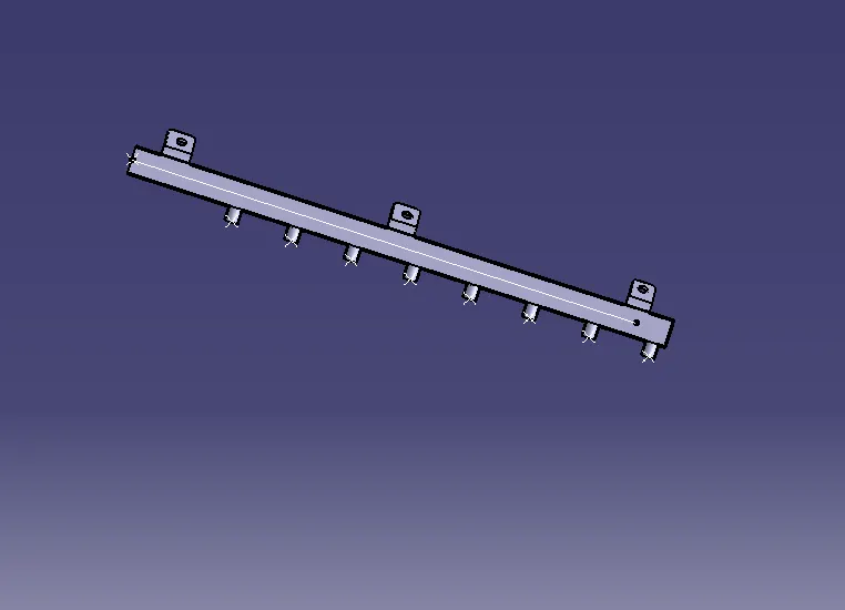
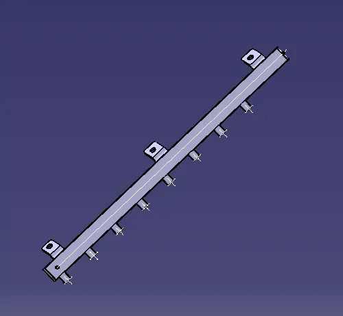
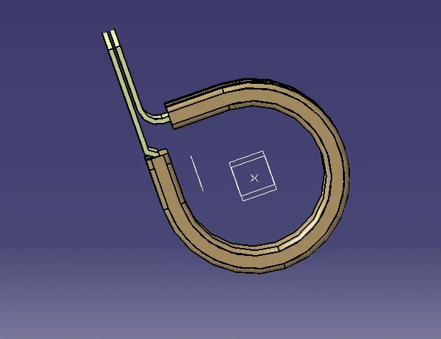
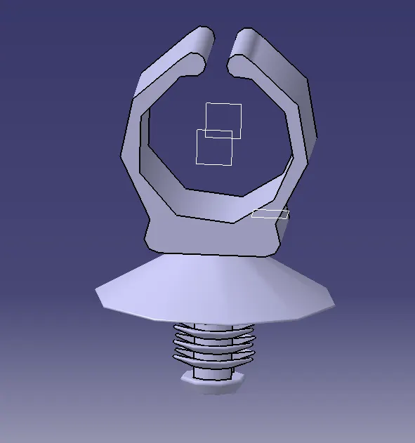
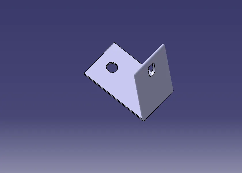
- After this we have to define the support equipment. For that open the p clamp and fir tree clip cad data in the mechanical oart design workbench and define two entry and exit planes with points and a base plane. Open electric part design and define the p clamp and firtree clip as support twice, as both sides can be entry and exit for the bundle segment
Wiring harness routing
- After inserting and placing all the required connectors, clips and channels required the next step is wiring harness routing.
- Switch to Electrical harness assembly workbench
- Define the assembly as electrical assembly and start routing
The routing starts from the interconnection connector:
- First in the bundle segment, by selecting external curve, a bundle segment has been generated. After adding branch points, bundle segments which connect the channel bundle segment to all the connectors have been generated.
- Similarly, bundle segment has been generated at the symmentrical channel assembly too.
- To route the wire harness, we started from the interconnection connector and then directed the bundle to the P-clamps and the guiding channels. To enable routing to various connectors, branch points were added to the main branch of the harness.
- By adding branch points, we can ensure that each connector receives the required signals and power while minimizing the length of the wire segments, which reduces the overall weight and cost of the harness. Additionally, branch points allow for more flexibility in the design, as changes in the routing or components can be accommodated more easily without affecting the entire harness.
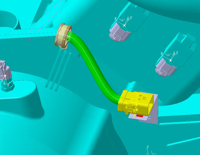
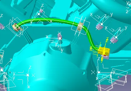
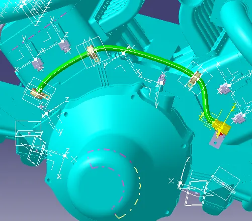
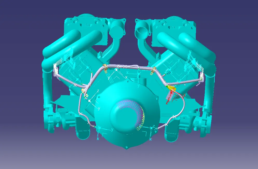
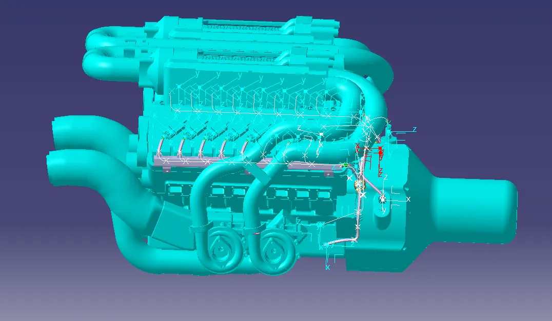
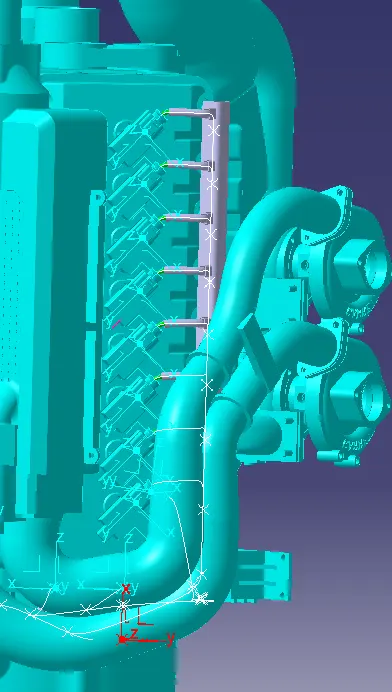
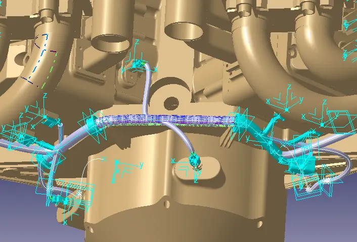
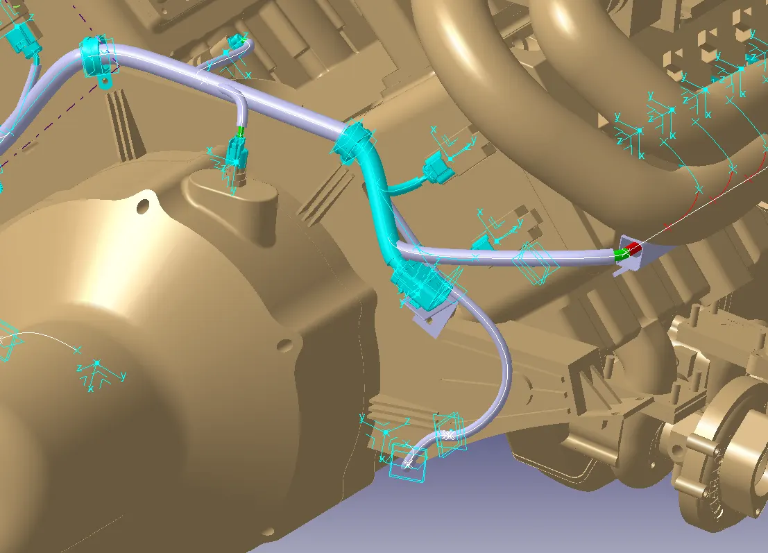
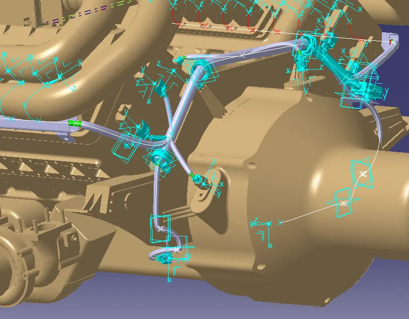
differents view for proper visibility-
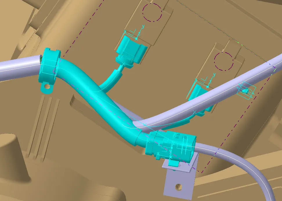
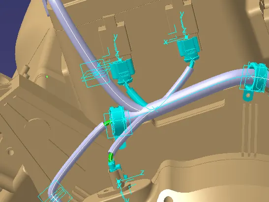
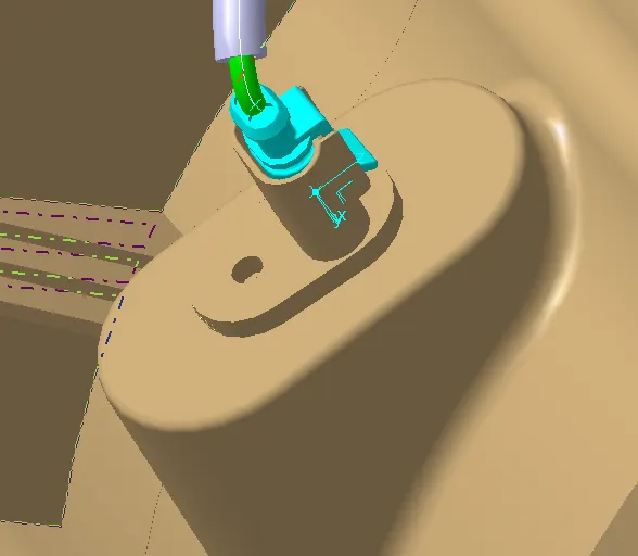
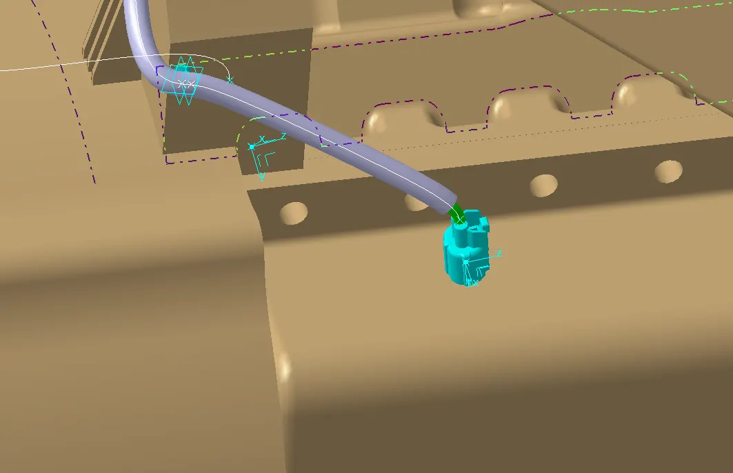
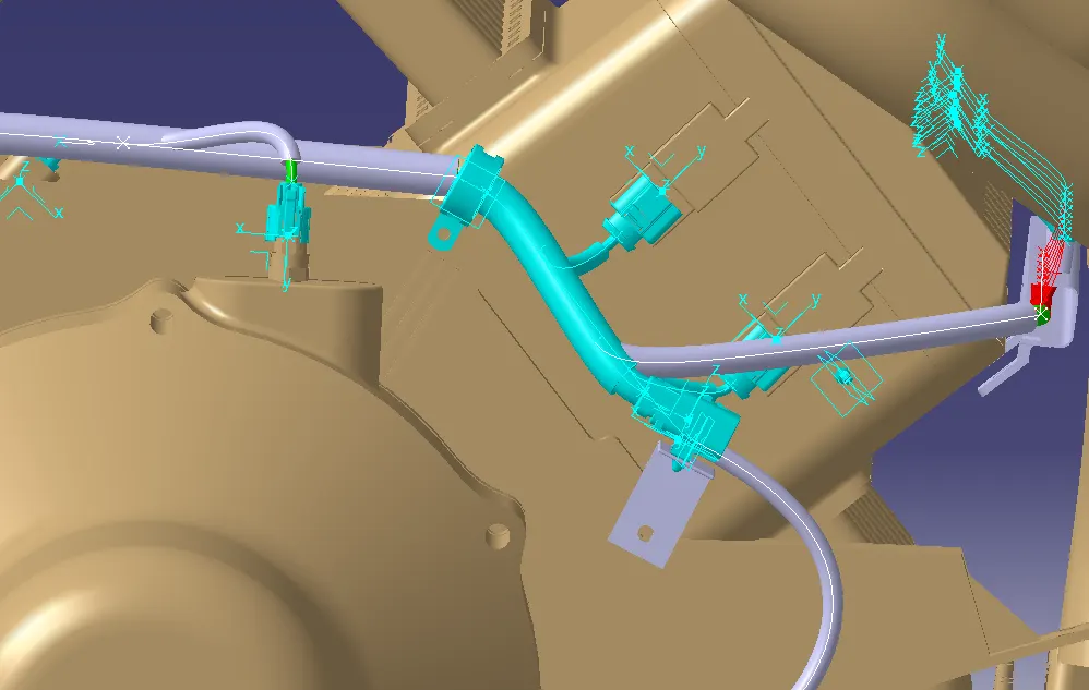
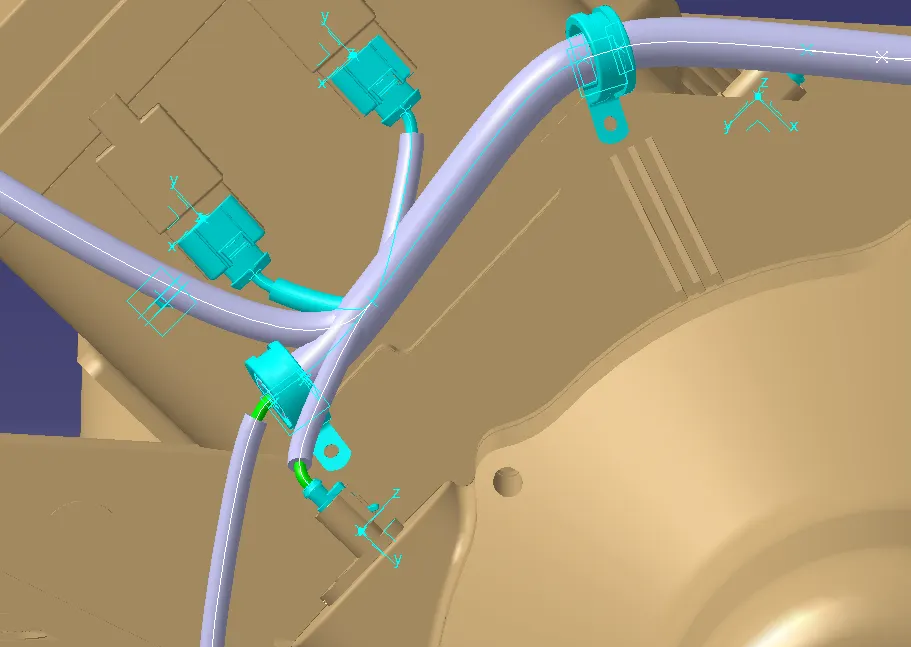
The main harness is given diamater of 15 mm,whereas the 4 pole connector wirings were given diameter of 10 mm and other connectors wire diameter is taken as 8 mm.
 mk
mk
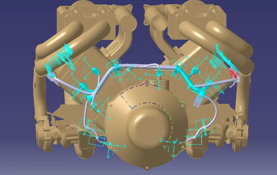
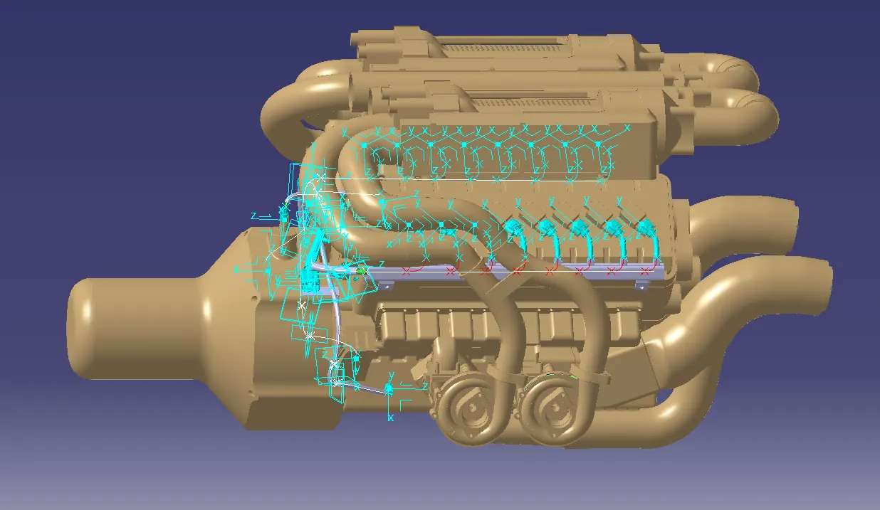
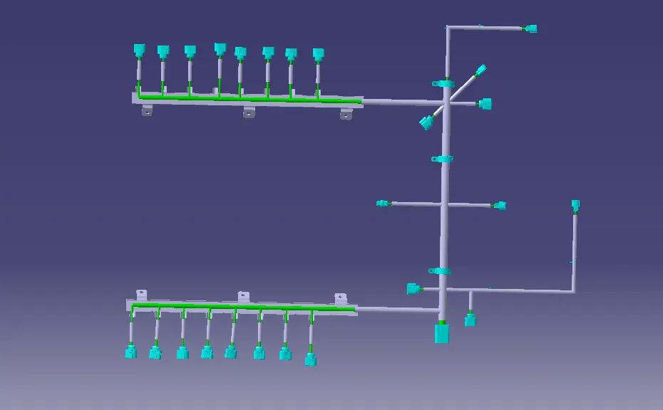
Final view after completing wiring harness routing:
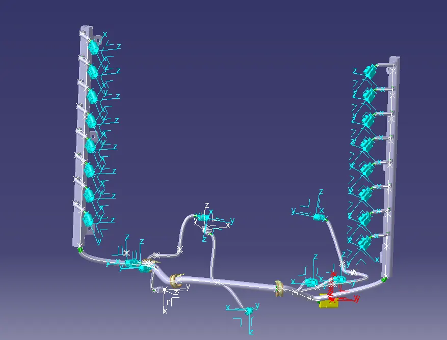
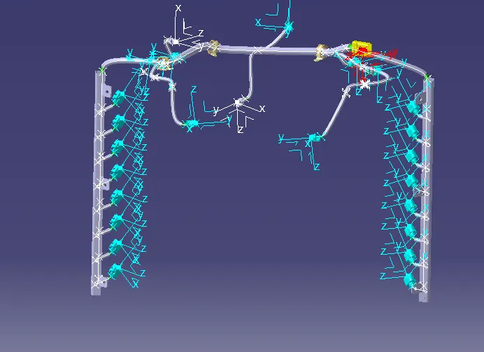
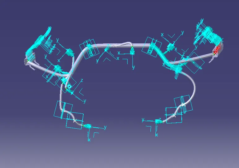
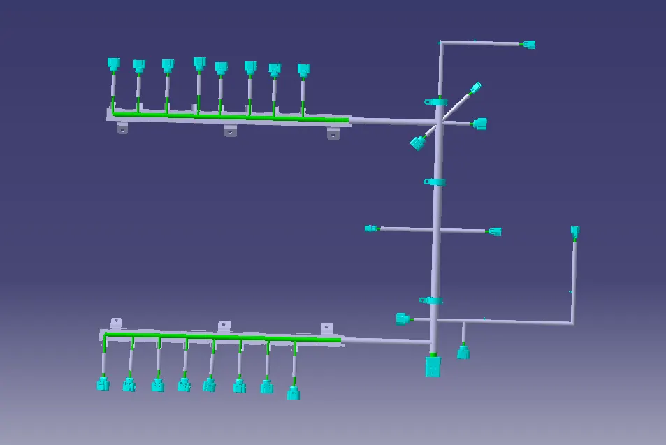
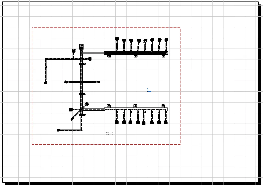
:Flattening
- Create a new product file for flattening and save in same folder. Open both harness flattening and main assembly parellely
- In Harness flattening Workbench, first add flattening parameters like orientations, scaling, drawing and others
- After adding them all the options for doing the operations are going to be available. Now extract the geometricle bundle in flattening workbench.
- After extract, we have to flatten it and for that we have to use flatten command, then by using rotate, bend and other features the flatten geometrical bundle is generated
- Now we have to auto update for any flatten links and synchronize.
Converting the flattened wiring harness to drawing
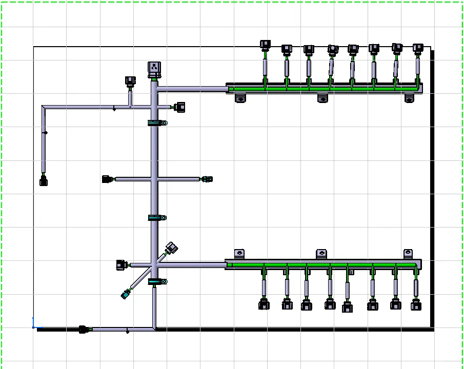
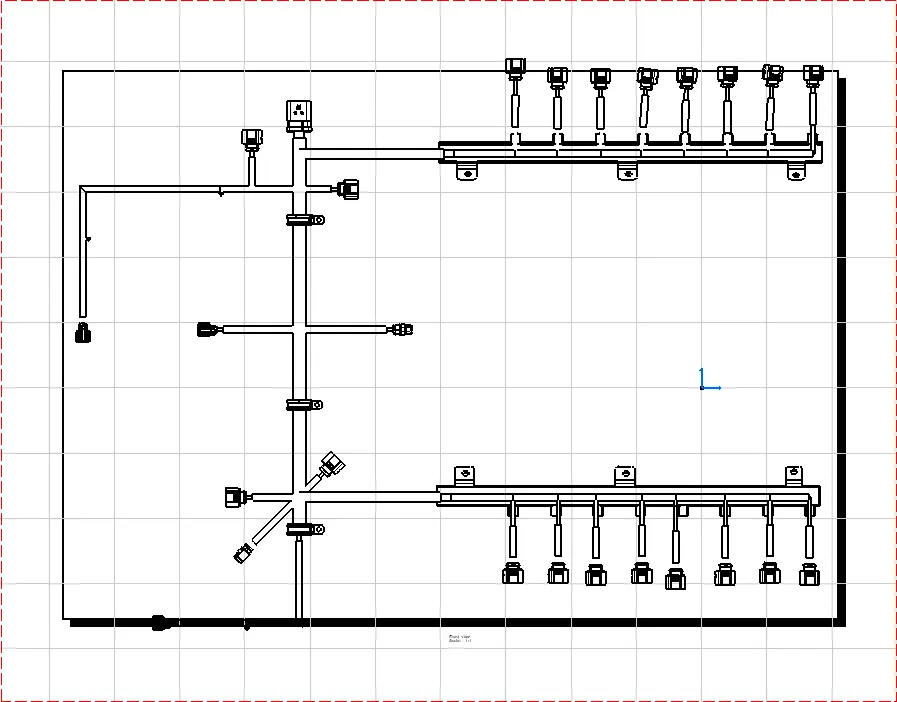
- Create a new file of drawing and place the wiring harness flattened view.
THANKYOU
REQUIRED FILES ARE ATTACHED