Week 9 - Challenge 2 - Switch Bezel Design
DESIGN AND DRAFT ANALYSIS OF SWITCH BEZEL
AIM-
Aim of the project is to design the switch bezel and to do a draft analysis for if by creating the required tooling direction with the help of bisecting method.
INTRODUCTION-
The control panel bezel is the frame part of the window switch that holds its switch covers and buttons into place. Molding is the method used to manufacturing the plastic trims of an automotive by most OEM’s, hence by considering the manufacturing consideration the switch bezel is designed.
- creation of tooling axis
- creation of class B and class C
- Creation a solid part out of surface modeling
- Draft analysis of class A surface and final plastic component.
Design consideration-
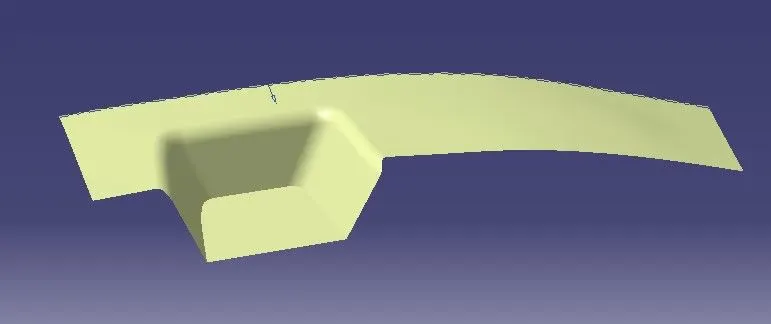
Class-A surface- A surface made by the designer which is given as an input to the plastic modeler to work on. It is aesthetic surface and the outer most surface.
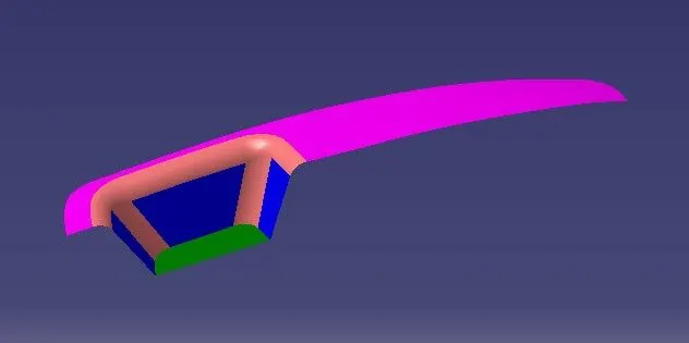
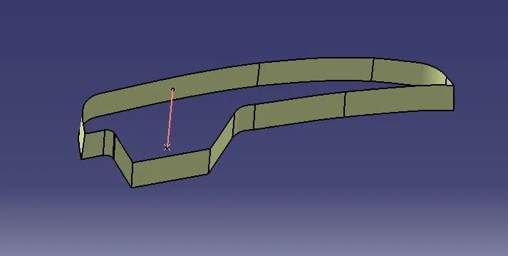
Class-B surface- A surface below a certain thickness from the class A surface is class-B surface, this is the surface that contains engineering aspects of a model.
Class-C surface- A surface that joints class-A and class-B is called class-C surface.
METCHODOLOGY-
For create this model we have focused on the following things-
- Tooling axis
- Draft analysis
- Class-B surface
- Class-C surface
- Making a solid model from surface following tools were used to reach the final steps-
- Extract
- Surface trim
- Extrapolate
- Offset
- Edge fillet
- Boundary
- Sweep
- Join
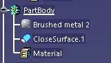
- Close surface
PROCEDURE FOR CREATING THE SWITCH BEZEL-
- First, the given styling surface is checked for any irregularities and if found any then it is corrected by using trim, extrapolate, split and join command.
- The below image shows that the class a surface Is clean and no irregularities present, so let’s move on to next step.
Creation of tooling direction-
- Consider the ejection from the cavity of the mould after manufacturing the interior trim must have the nominal 3-degree draft angle.
- Hence the tooling direction is created by considering the above factor and bisecting method used.
- The base surface of the class-A was extracted and a point with the feature is disable.
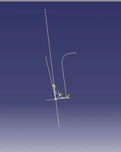
- Then, using project intersection along YZ plane is created and the two positioned sketch.
- Then bisecting lines with the two inclined lines were drawn.
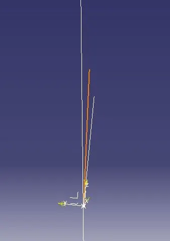
- Now the same procedure is done along the XZ plane but on one side we don’t have inclined lines so the center point is used to extrude a line along the Z-direction and gave a measurement of 5degree.
- With these two lines from sketches 1 and 2 the bisecting line is created and published as tooling direction.
Creation on class B-surface-
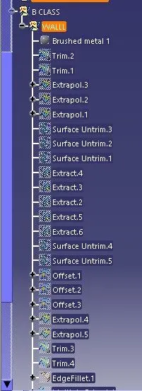
- For creating the class-B surface the required surface except the offset surface have been extracted and then untrimmed all the surface.
- Then all the surface have been extrapolated to get intersections between them.
- Since the thickness of the switch bezel is 2.5mm the B- surface was offset to 2.5mm and the required trim operations must be carried out.
- Finally the required corners have been filleted to 12.5mm (15-2.5mm) .
Creation of class-C-
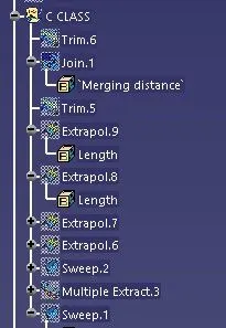
- The required outer edges of the A-surface were extracted using multiple extract. Then for avoiding the patches the curve is smoothened using the curve smooth options.
- Then by using the sweep command the surface was created with the following feature control.
- Angle-3degree
- Lengh-20mm
- Then suing the extrapolated the edges were intersected between the surface corners which eases the trimming operation.
For draft analysis-
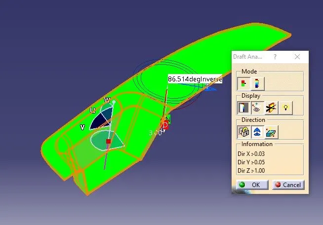
- Go to the insert>analysis>feature draft analysis.
- Align the tooling axis with the compass.
- Click on the surface and se that the surface is within the permissible limit of the draft value which is 3 degree.
- The surface should be green and in the column nominal value 3deg given as an input hence the draft analysis on the class A surface is successfully performed.
Following the similar steps performed for the draft analysis of class-A surface we obtained the following results
The draft analysis command enables and to detect if the part drafted will be removed. This type of analysis is performed based on color ranges identifying zone on the analyzed element where the deviation from the draft direction at any point corresponding to specified value.
By selecting the tooling axis and publish class-A , class-B , class-C.
Steps which have applied-
Wall of the switch bezel-
Base surface-
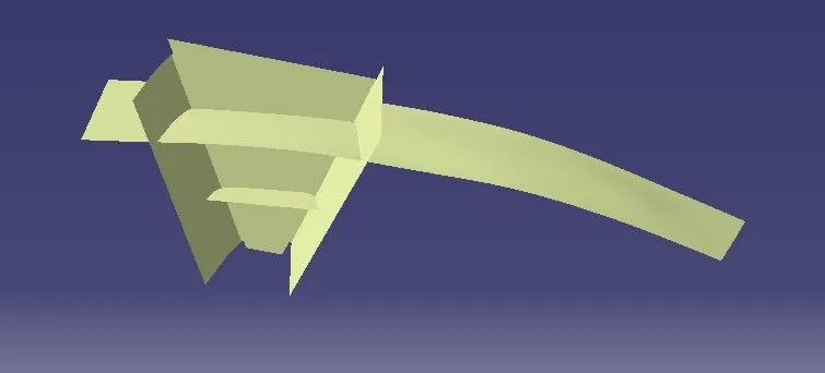
Trim the extra part-
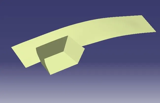
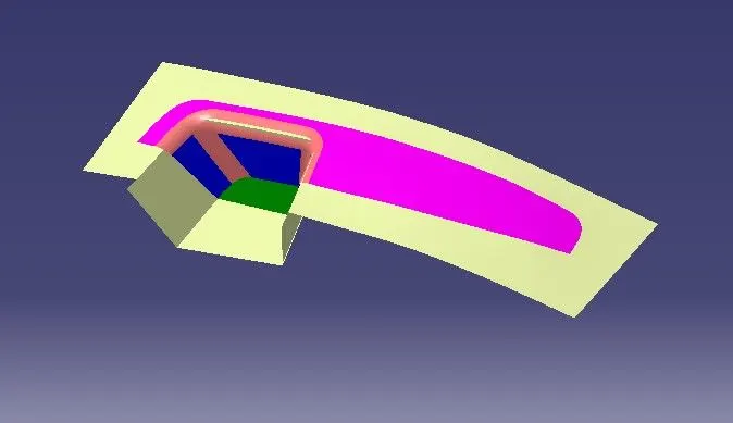
Appplied the fillets-
C-Class surface-
Join the A-Class surafce with C-Class surafce-
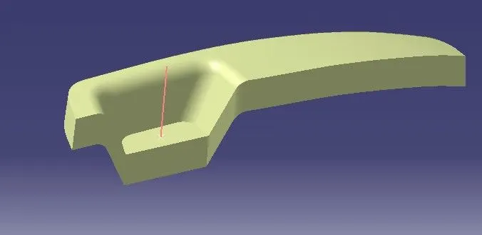
Trim is applied -
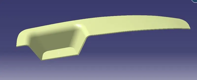
Comkplete part-
Thicken part-
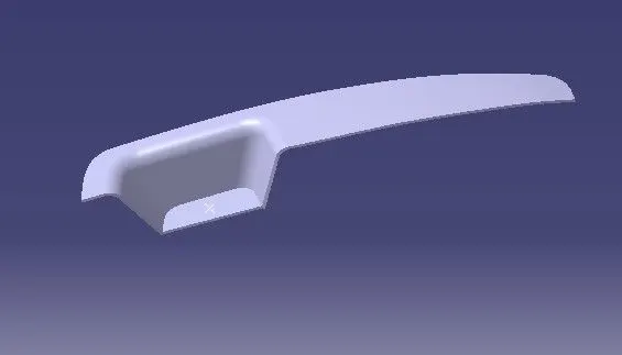
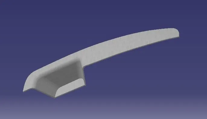
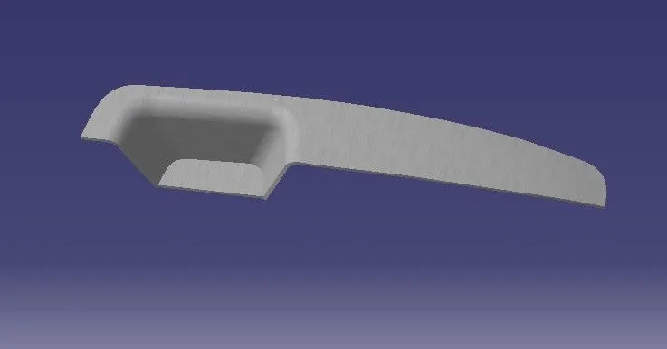
Diffrent views of the part-
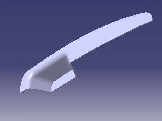
The elemtns which is use for all surface-