Week 12- Final project
- FINAL PROJECT
DOOR TRIM PANEL
AIM - Creation of CAD model considering following inputs as like in OEM and tier1 companies.
- Class A surface
- Nominal thickness
- Attachment strategy
SOFTWARE USED - CATIA V5
Theory:
Role of plastics in the Automotive industry
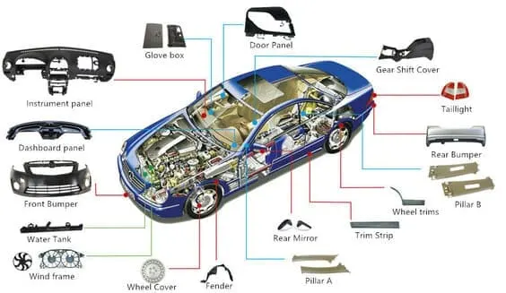
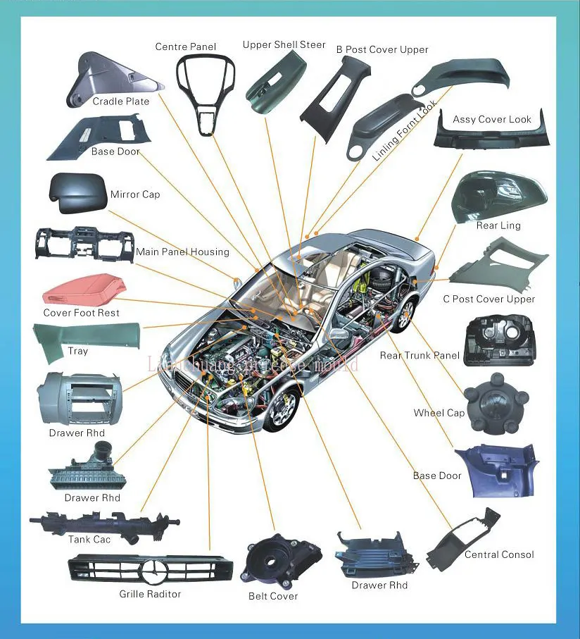
The automotive industry is the third most important consuming sector of polymers after packaging and building and construction.
The role of plastic in the design and manufacturing of automotive vehicles has never been more essential, with stringent regulations and changing consumer habits driving demand for more affordable, lightweight, and fuel-efficient vehicles. Fuel efficiency has become one of the most important features in automotive vehicle design due to the rising fuel prices and stricter environmental regulations.
There are about 30,000 parts in a vehicle, out of which 1/3 are made of plastic. In total, about 39 different types of basic plastics and polymers are used to make an automobile. More than 70% of the plastic used in automobiles comes from four polymers: polypropylene, polyurethane, polyamides and PVC. Plastic has become one of the key materials required for the structure, performance, and safety of automobiles in recent years, with growth in plastic consumption being driven by light-weighting trends for fuel efficiency and consequently lower greenhouse gas emissions.
Given Data :-
- Class A Surface for Door Trim Panel -
As we know in automotive industry there are complex products that we have to design but this is not possible with simple sketches for that we need Class A Surface.
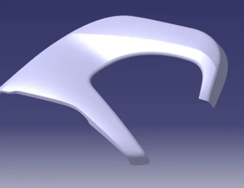
The A-surface or the styling surface is first checked for any gaps and other issues in its surfaces. This Surface acts as the input surface so any correction to be done should be with approval from the styling team or done by them. A- perfect surface is the one when a boundary is created, the lines are only on the edges of a component and its holes or cutouts as shown below.
DOOR TRIM PANEL CONSISTS OF FOLLOWING COMPONENTS:
1.DOOR ARM REST
2.UPPER MAP POCKET
3.LOWER MAP POCKET
4.LOWER SUBSTRATE
5.UPPER SUBSTRATE
6.FLANGES
8.HEAT STAKES AND DOG HOUSE
Steps Follwed for Completion of Project :-
The door trim panel is created by follwing steps -
- To check given Class A surafces for any modification.
- To segregate given surafces into separate part body namely Lower Substrate , Arm Rest , Map Pocket , Bottle Holder.
- To work individually on each part.
- To create tooling axis for part.
- Draft analysis on class A surafce.
- Creation of class B and Class C surafce.
- Craete closed body from Class A , B and Class C surface.
- Follwed same procedure to craete all parts .
- Then create attachement features for all parts.
- Then do Draft analysis on final parts and then constrain them for assembly.
ARM REST
In the front of the car, a central armrest, which commonly folds away based on user preference, will also often include a storage compartment and sometimes even cup holders. Some also provide the location for controls for non-essential functions of the vehicle, such as climate control or window motors.
For the Arm rest design the input class a surface provided is To check whether the surface has any oen boundaries use the boundary feature then we can identify that there is an open patch or the surface which we need to work on
Boundary for the part-
-Tooling direction for the part-
In case of the arm rest we generally deploy the bisection methiod for creating the tooling axis , that is first we need to create a plane and form an intersection of the surface and generate the two lines from the intersection and there by creating a line by using the bisection method
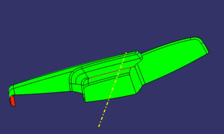
Draft Analysis-
Generating of the class B surface
For the class B surface generation refer to the master section provided to measure the thickness of the plastic component then offset the class A surface to an extend of 2.5 mm thickness beneath the class A surface.
Generating the class C surface:
For the class C surface generation we use the class A surface as an reference and follow the draft with respect to the reference surface and the main tooling axis.
FINAL TRIM OF CLASS-B WITH A & C
Generating the final close surface:
After creating the class B and the class C surfaces join the class A and the class C surfaces and trim the resultant with the class B surface then the resultant surface is the final closed surfaces.
CLOSE SURFACE-
v
Map pocket design:
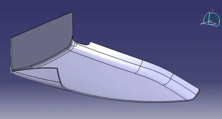
Map pocket is the sub element situated right at the hub of the lower substract of the door trim panel . The processs illustrated is same as the prevous components first, we need to check the boundary of the given input surface whether there might have any open patches or else protrude the input surface as the required class A surface
The provided input surface is .
find out for any open patches by checking the boundary feature.
Tooling axis creation:
In case of the map pocket the we extract the surface in the Y direction orientation and use the point - direction to generte the tooling axis of the map pocket
Draft analysis of the class A surface:
Once the tooling axis is create analyze the draft for the class A surface with a draft angle of 3 degrees
Class B surface creation:.
Now step forward to create the class B surface deploy the 2.5mm offset of the class A surface to generate the class B surface beneath the class A surface
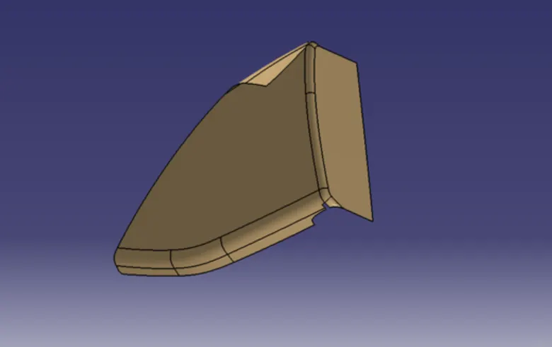
Class C surface creation:.
for the map pocket
FINAL TRIM OF CLASS-B WITH A & C-
Draft analysis of the solid body:
- Now perform the draft analysis with a draft angle of 3 degrees on the solid body
- The results obtained are
CLOSE_SURFACE_
BOTTLE HOLDER-
Check for the open patches if exists , here in case of the bottle holder the oe particular surface is creating a problem in the further solid body creation . So ,here we use the join command and use the sub elements to remove feature to remove the particular surface from te input one and use the multisection feature to complete the class A required surface
Tooling axis creation:
Draft analysis of the class A surface:
Perform the draft analysis of the class A surface with a draft angle of 3 degrees the result obtained is
In the draft analysis some of the patches are red ( the draft is 0 or below zero ) and some in blur region shows that the draft is ( greater than 0 and less than 3)
So we need to report to the class a team as te draft on the given input surface is not appropriate and need to get an update a class A surface So in this we need to continue forward with this draft analysis results for the further creation
Class B surface creation:
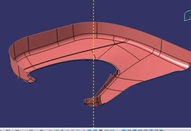
Now offset the class B surface to 2.5mm following the master section beneath the class a surface and extrapolate the class b edges to an extent to form the proper ytrim with the class A and C join Choose the correct direction for offsetting the surface
Class c surface creation:
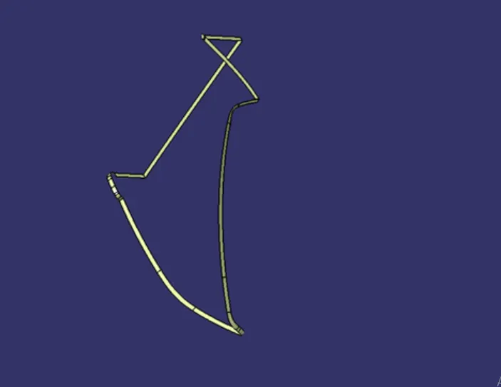
Now create the class C surface with the aid of the class a surface and the sweep feature along the draft direction and the reference surface parameters . So provide adraft of 3 degrees along the draft direction making the direction of the draft as the main tooling axis and 90 degrees draft with rreespect to the reference surface
Final surface creation :
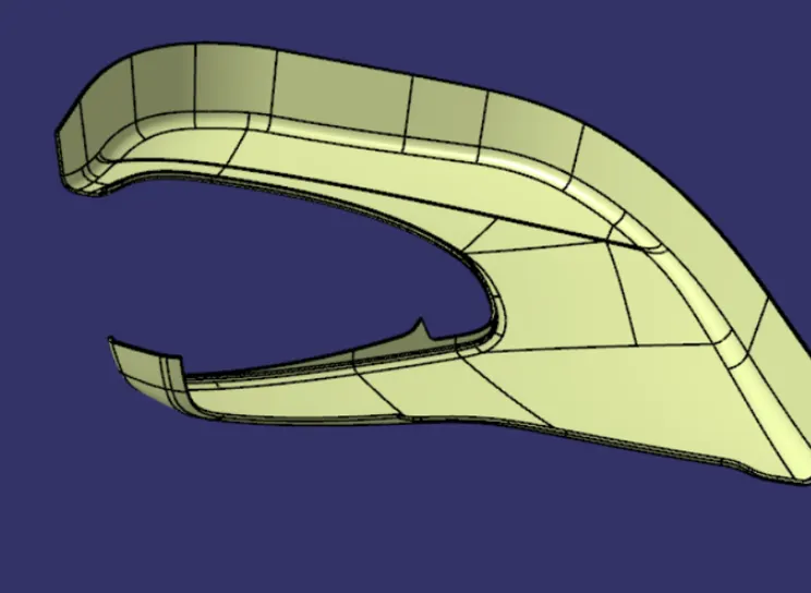
Once all the surfaces are created that is the class B and the class c surfaces join the class C surface with the classs A surface and trim the joined surface with the class b surface
- This is the final closed surface with the class B & C surfaces
- Solid surface creation:
- Once the closed surfae is created then go to the part workbench and use the solid surface feature to generate the solid body out of it
-
aft analysis of the solid surfcae body:
perform then draft analysis of the solid body with a draft angle of 3 degrees
The obtained results are the
2.LOWER SUBSTRATE=
Step 1: Design Check (Pre Check) on received Class A :-
- After receiving the Class-A for the connectivity of the surfaces on it.
- Use boundary operation and disassemble.
- Check for discontinuous Surface.
- The check is over if any discontinuities do not arise.
TOOLING_DIRECTION-
DRAFT_ANALYSIS-
B-SURFACE-
C-SURFACE_
- This is the final closed surface with the class B & C surfaces
CLOSE_SURFACE_
FLANGES-
FLANGES-Flanges are the elements that are needed to join different components together. So here I have to make flanges on the door armrest and the map pocket. Following the master section, given as the input basically the measurements and location of the flange. I have created the flanges. First I have created the flange on the outer map pocket. For creating the flanges I have taken extraction of the curve and made a point on that curve then created one plane on that point followed by creating a sketch on that plane taking the point created as the origin. The sketch is shown below:
Map pocket design:-
BOTTLE HOLDER-
After creating the flanges I have created the dog house.
Dog House-Dog house is an engineering feature used in the plastic trim design. Doghouses are used as supporting features. Sometimes other engineering features like snaps; locators, etc. are mounded on them to increase their strength. Dog houses are subjected to draft analysis to prevent breakage of the component during ejection from the mold cavity. Dog house and other engineering components are built on B-surface.
DOG HOUSE
- Dog house is an engineering feature used in plastic trim design. Dog houses are used as supporting feature. Sometimes other engineering features like snaps; locators etc. are mounded on them to increase their strength.
- Dog houses are subjected to draft analysis to prevent breakage of the component during ejection from mould cavity. Dog house and other engineering components are built on B-surface.
- Thick sections waste_material and are simply uneconomic. So solid shapes that would do the job well in wood or metal must be transformed to a 'shell' form in plastics.
- Tooling must be cleared for easy ejection of the component, from the core cavity. In order to clear tooling certain value of draft is given to the component. Minimum of 2-3deg is provides on all plastic components.
Then I have extrapolated the inside portion that extracted and trimmed it with the base which saran offict of 4mm The show
After splitting
using this sketch i have creating complete dog house
LOCATORS
- Extract the surface that we going to create locator
- Use positiioned sketch and draw a locator sketch
- Use pad commands for the sketch to till we required
- Draft the locator for minimum of 0.5 degree
- Add fillet 0.5mm o all faces
- Assemble the locator to lower subtrate solid
- Maintain a 50mm minimum between two locator
- Translate the locator to wherever we need
- Trim the all heat stakes with lowersubstrate solid
- Maintian a height more than heat stake
-
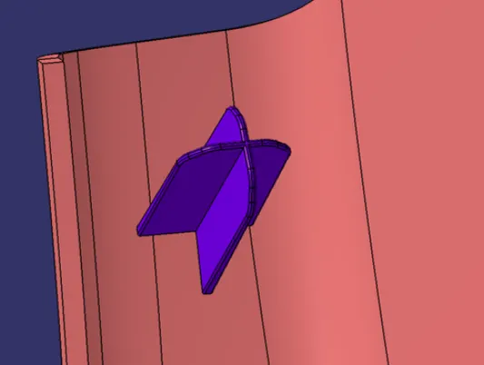
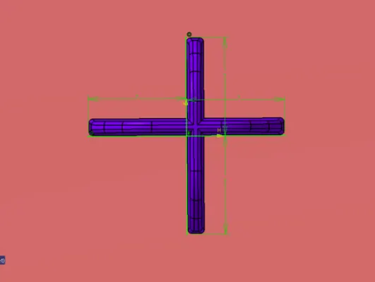
Sketch Plane is made in the tooling axis direction.
Height = 20 mm
Wall Thickness = 1.3 mm
Draft Angle = 0.5°
Chamfer = 3 mm, 45°
Fillet 0.3 mm & 3 mm
-
-
Heat Stakes and Ribs:
-
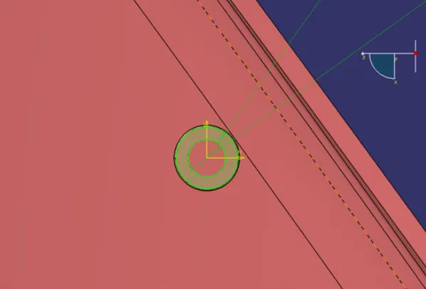
The use of heat stakes is to attach two plastic components permanently. A total of 13 heat stakes were placed at different locations on the lower substrate. One heat has been created onto the door armrest part which will be attached to the upper substrate. Following the muster section, the outer diameter of the heat stake is 7.5 mm and the inner diameter is 4.5 mm. Necessary slots are made onto other parts where heat stakes will attach together. Draft of 0.5 degrees has been given to all the heat stakes. All the heat stakes have ribs attached to them. All the ribs have 1mm thickness and 0.5 degrees of the draft. The length of the ribs is 14 x 14 mm.
Heat staking also known as thermoplastic staking is the process of joining two dissimilar materials together. In heat staking, we use local heating and cooling to raise the temperature of plastic components and allow plastic reforming to be carried out. This reforming can be used in a wide variety of applications.
-
Heatstakes is known as thermoplastic staking is the process of joining two dissimilar metals together
- Extract the surface that we going to create heat stake
- Use positiioned sketch and draw a heat stakes sketch
- Use pad commands for the sketch to till we required
- Draft the stakes minimum of 0.5 degree
- Add fillet 0.5mm o all faces
- Assemble the heat stake to lower subtrate solid
- Maintain a 50mm minimum between two heat stakes
- Translate the heatstakes to wherever we need
- Trim the all heat stakes with lowersubstrate solid
-
Sketch Plane is made in the tooling axis direction.
The length of heat stakes should be at least 5 mm lesser than locators, L = 15mm
Radius, ID = 5mm, OD = 7 mm
Draft Angle = 0.5°
-
Procedure to create ribs on lower substrate
Step 1: Create a sketch and create a surface . Use thick surface option to obtain ribs in required shape .
- Draw the inner wall ribs for the dog house.
- draft_analysis-
-
Push pins-Push pins are used for joining one component to another. These are basically attached to the dog houte For creating the push pins I have taken the following reference basically the measurements
-
Then I have made the cut out on the dog house for inserting the pin. For the cut out I have made one sketch on the top surface of the dog house and extruded it.
Then I have split the extrude from the dog house to get the cut-out. The cut out for the push pin is shown below.
- ALL-PART=
Final-Part-
Different view with different colour-
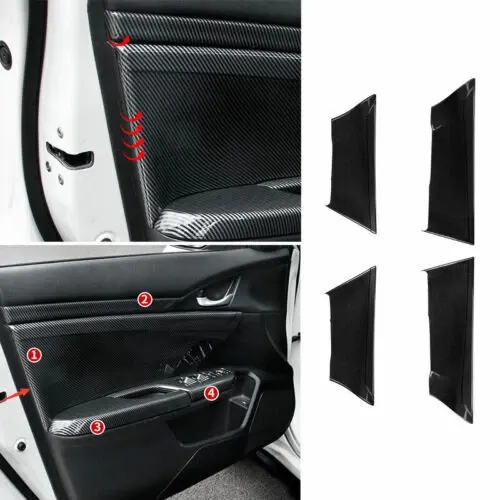
After_Manufacturing it_will_look_like-
STEP 7. CREATION OF PARTING LINE-
CONCLUSION:
Thus the door interior part has been created from the inputs of class A surface along with the master section by following the design rule followed in tire 1 and OEM industries in CATIA v5.