Week 10 - Challenge 3 - Door Trim Lower with Engineering Features
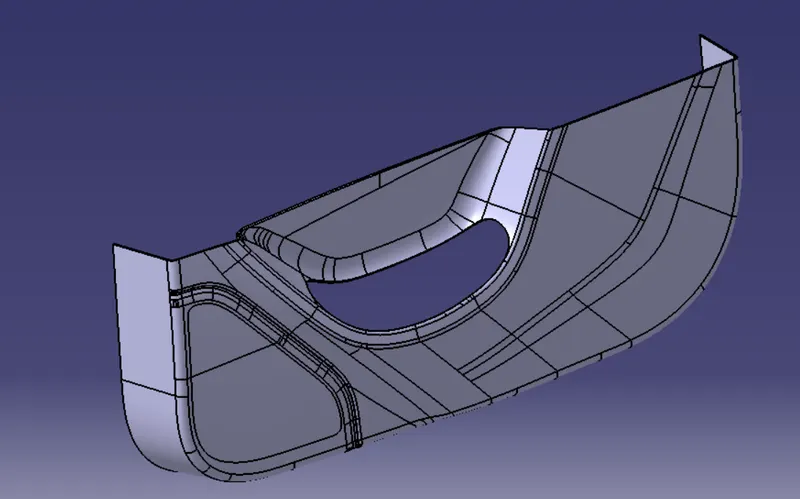
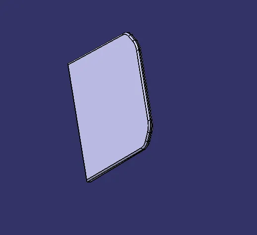
OBJECTIVE: To create the Door Trim Lower's Plastic Component using the Class A Surface that is provided. Desired Thickness of the Plastic Component is 2.5mm with 3.2 degrees as the Draft Angle.
Overview:
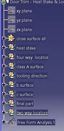
Initially, we need to offset the given Door Trim class A surface in the inner direction to the required thickness (here the thickness is 2.5mm). After that, we need to close the patches on the offset surface of the bumper, the patches are formed due to the fillets on the Class A surface. Once all the patches are closed properly join them together to make a proper class B surface and now sweep the boundary of the class A surface to trim with the class B surface to make a closed body. By using the closed body command in the Prat workbench we can get the solid body from the closed surface of the Door Trim. Now, I created the Heat stakes and Locators by considering all the design parameters. After creating all the B-side features on the solid part body of the door trim, I performed a draft analysis for it to check whether all the surfaces are drafted properly or not (The draft angle for the plastic component is 0.5deg to 3deg).
TOOLING AXIS:
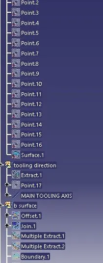
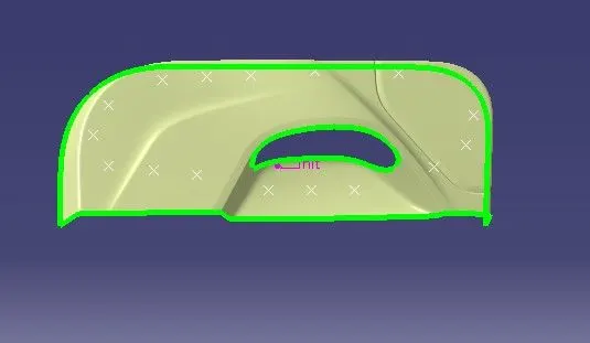
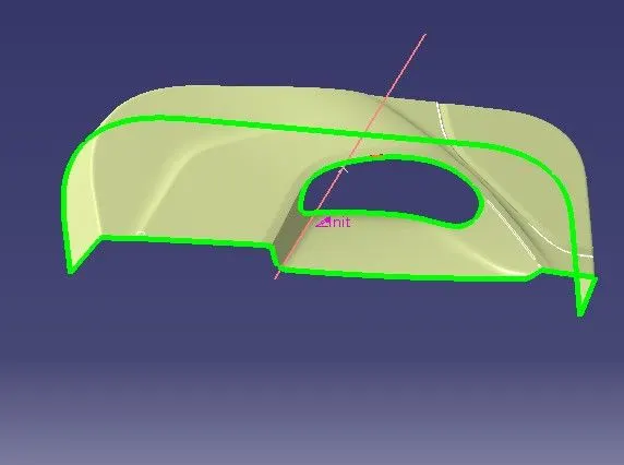
To create the tooling axis, I extracted a surface from class A and created a point in the middle of the surface by using the point command and created a line at that point through the x-axis. Now, I performed a draft analysis check from that line whether the created tooling axis is in the correct position or not. If in the draft, analysis check the surface highlighted with green colour on both sides of the surface the tooling axis is in the correct position and direction.
Tooling axis:
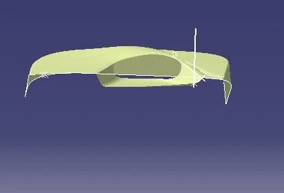
APPLY COLOUR ON THE TOOLING LINE-
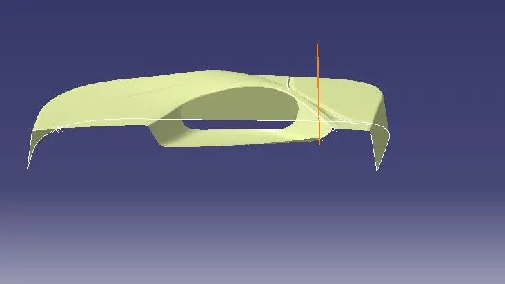
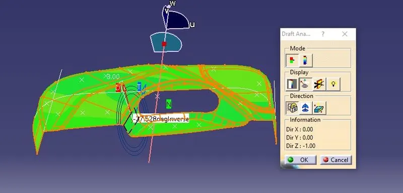
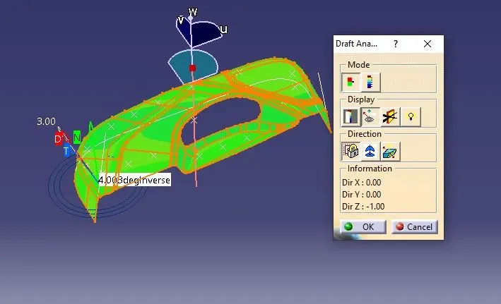
DRAFT ANALYSIS FOR CLASS A SURFACE:
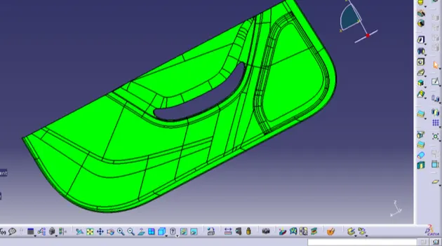
We do perform the draft analysis check for class A surface before we make solid and creation of B-side features. Initially I align the compass to the tooling axis and I gave a 3deg draft angle for the green colour in the colour bar. If the surface is highlighted in green colour the draft angle is given properly for class A surface. If the class A surface is not highlighted fully in green colour, that might be the reason for the draft angle of the class A surface.
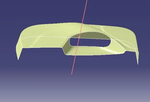
A CLASS SURFACE -
A Surface is the aethetic surface part of the model by using this as reference the other b surface and c surface is created.the aesthetic body part is part which should not go through any change in the aesthetic body itself.
CLASS B SURFACE:
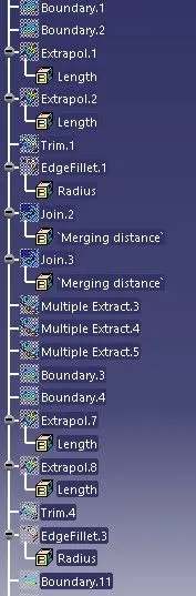
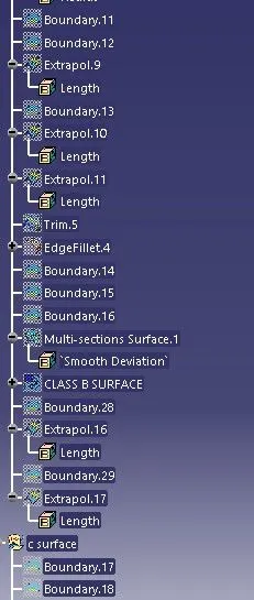
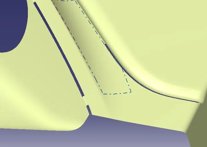
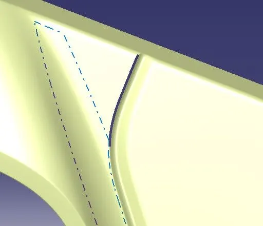
To create the class B surface, offset the class A surface inside as per our thickness requirement (here the thickness is 2.5mm, so I offset the class A to 2.5mm inside). Once the offset is created, we can observe some patches on the offset surface by taking the boundary for the offset surface, those patches are formed due to the fillets on the class A surface. We need to cover those patches with the help of the multi-section surfaces command by extracting the patch boundaries. Once all the patches on the offset are covered properly join all the patches with the offset surface, to get the replicated surface of the class A surface.
PATCH IS GOING TO CREATE -

NOW COMPLETLY SURFACE IF GOOD-
CLASS C SURFACE:
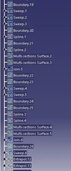
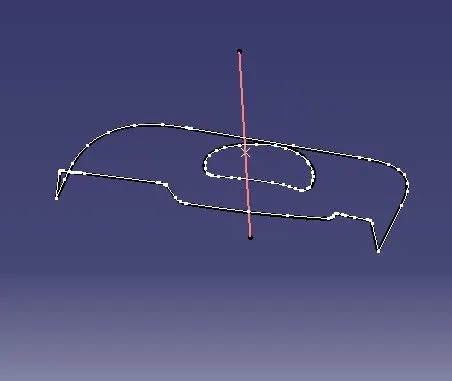
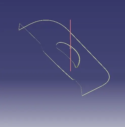
I used the sweep command to create the class C surface concerning the boundary of the class A surface. Initially, I extracted the boundary of the class A surface with tangent continuity, and I sweep the extracted boundary concerning the surface at 93deg (for draft angle) for 4mm to intersect properly with the class B surface. Once we sweep all the surface boundaries of class A, extrapolate the sweeped surfaces until both surfaces got intersect properly, and trim them to remove extended extrapolated surfaces to get a proper sweep boundary throughout the entire surface, including the centre hole of the door trim. Now, join both class A and sweep boundary to get the complete class C surface.
Class C surface:
PART BODY:
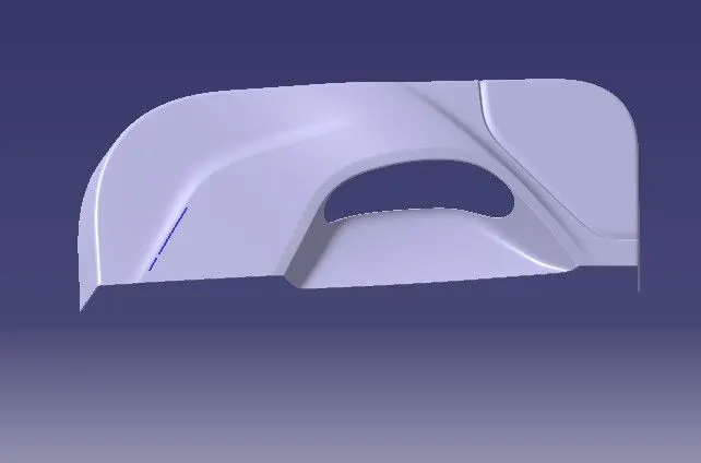
To create the solid part body from the closed surface, I used the closed surface command in the part workbench.
PROCEDURE TO ADD ENGINEERING FEATURES:
1. LOCATORS
2. HEAT STAKES WITH GUSSETS
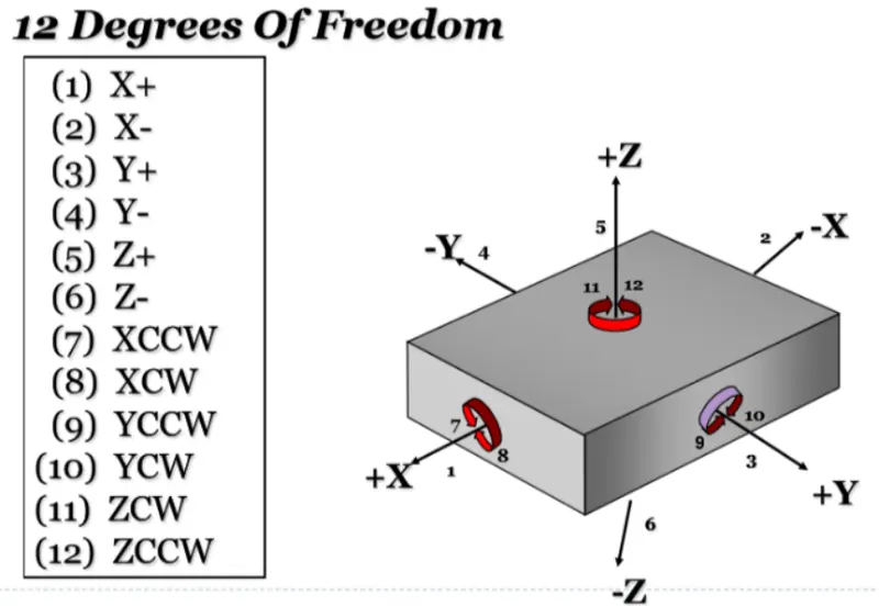
USE OF LOCATORS: Any workpiece has 12 degrees of freedom for movement in space that consists of 6 Axial and 6 Radial Degrees of Freedom. All 12 degrees of freedom must be restricted to ensure proper referencing of a workpiece. These 6 Axial Degrees of Freedom permit Straight-Line Movement in both directions along the 3-principle axis shown as X, Y & Z. The Radial Degrees of Freedom permit Rotational Movement, in both Clockwise & Counterclockwise radial directions around the same three axes.
We have two objectives when assembling the child component with the parent component:
1. Accurately position the part at the desired coordinates.
2. Restrict all degrees of freedom except the one direction in which it'll fix so that the part
PROCEDURE TO CREATE THE LOCATORS:
SKETCH FOR THE LOCATOR:
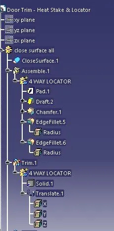
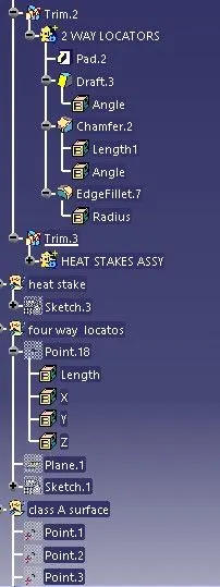
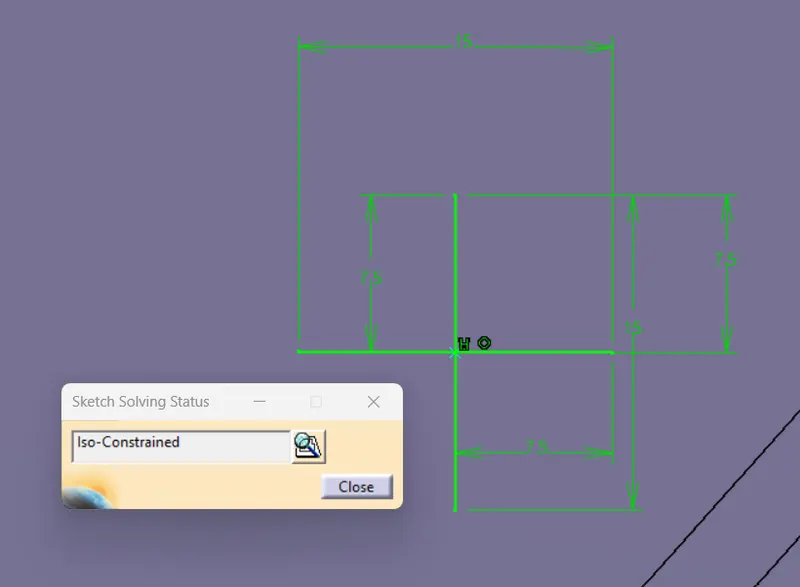
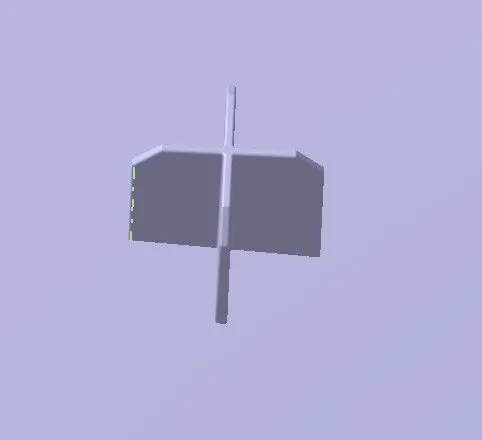
To create the locators, I created a sketch on the body. After creating the sketch, I pad it 20mm in height and thicken it to 1.3mm and I drafted it with 0.5deg in the direction of the tooling axis. I gave 3mm of chamfer with 45deg of inclination and after I gave a fillet of 0.3mm radius.
4-way locator:
TWO WAY LOCATORS-
CREATION OF HEAT STAKES:
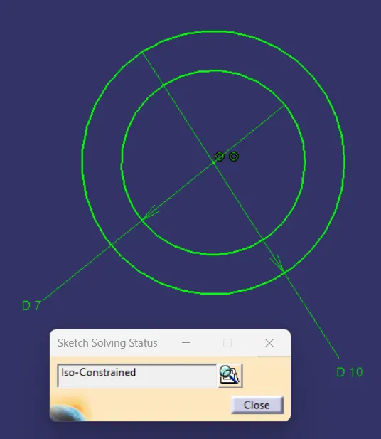
To create the heat stakes, I draw a sketch on the surface. After the creation of the sketch, I pad it to 15mm height and I gave a draft angle of 0.5deg on both sides (inside and outside) and then I gave a fillet with a 0.25mm radius. After creating the heat stake, I created the ribs for supporting purposes. To create the ribs, I draw a sketch and padded it to 6mm in height and 1mm in thickness. After padding the ribs, I drafted 0.5deg in the tooling asix direction and filleted it with a 0.25mm radius. Finally, I union trim the ribs with a heat stake to remove the ribs, which are present inside the heat stakes.
Heat stake sketch:
AFTER THE HEAT STAKES:
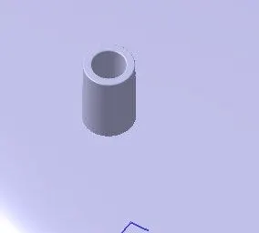
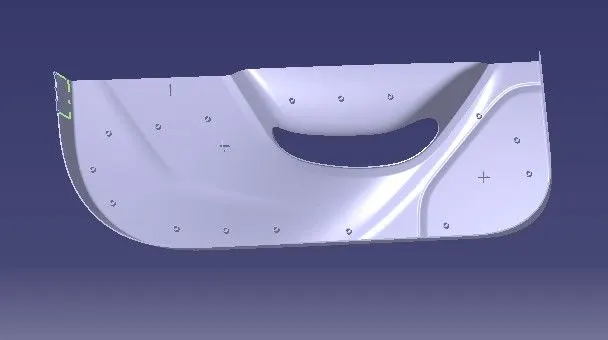
Now I translated the heat stakes by copy-pasting them in the part body according to the requirement.
Final part body with 4-way and 2-way locators including all the heat stakes with supporting ribs:
DRAFT ANALYSIS OF CLOSE BODY
Use the draft analysis to check the final product has minimum draft angle.
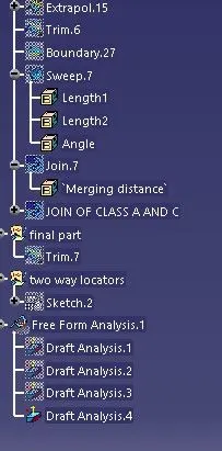
DRAFT ANALYSIS ON THE ENGINEERING FEATURES: