Wiring harness design in CATIA V5 - 3D modeling Week 7 Challenge
Wiring harness design in CATIA V5 - 3D modeling Week 7 Challenge
AIM-
- To define the mechanical parts electrically and prepare a geometrical bundle.
- To flatten the electrically defined geometrical bundle using wiring harness flattening workbench.
- To prepare a drawing of the flattened wiring harness assembly in drawing work bench.
INTRODUCTION:
CATIA Electrical Wire Harness Flattening provides automatic and complete flattening of 3D Electrical Harnesses for manufacturing documentation in a concurrent engineering environment.
BENEFITS:
- Seamless collaboration between harness designers and manufacturing to ensure accuracy of 3D information transferred to manufacturing.
- Best environment for harness detailed manufacturing documentation and form-board design.
- Reduce effort for generation & maintenance of 2D harness drawings.
- Integrated design to manufacturing process with the support of design changes.
- Reduce cycle time with the ability to reuse existing documentation.
-
Once a product is ready to manufacture, its design must be precise or it risks costly errors and delays. Collaboration is the essential key to successful documentation and design between harness designers and manufacturing.
CATIA – Electrical Wire Harness Flattening provides automatic and complete flattening of 3D Electrical Harnesses for manufacturing documentation in a concurrent engineering environment.
Customer Benefits
- Seamless collaboration between harness designers and manufacturing to ensure accuracy of 3D information transferred to manufacturing
- Best environment for harness detailed manufacturing documentation and form-board design
- Reduce effort for generation & maintenance of 2D harness drawings
- Integrated design to manufacturing process with the support of design changes
- Reduce cycle time with the ability to reuse existing documentation
DESIGN METHODOLOGY
-
STEP-1
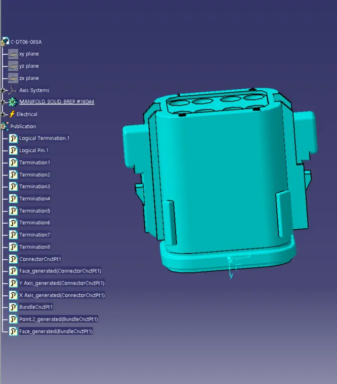
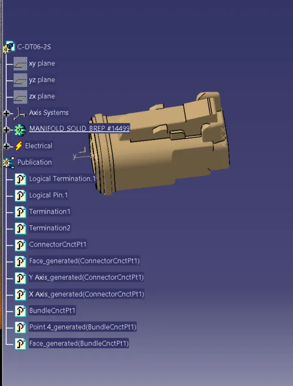
EFINING CAT PART AS CONNECTORS:
Fig2: Connector(DT06-6S)
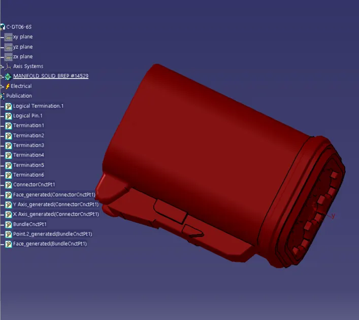
Fig1: Connector(DT06-4S)
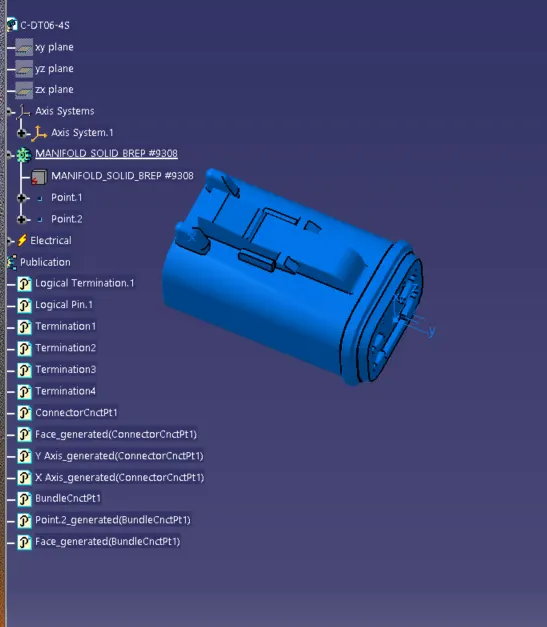
Fig3: Connector(DT06-08SA)
- DT06-4S
ARRARRANGED CONNECTOR AT THE PLACE -
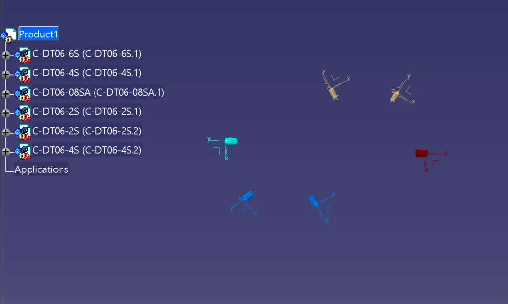
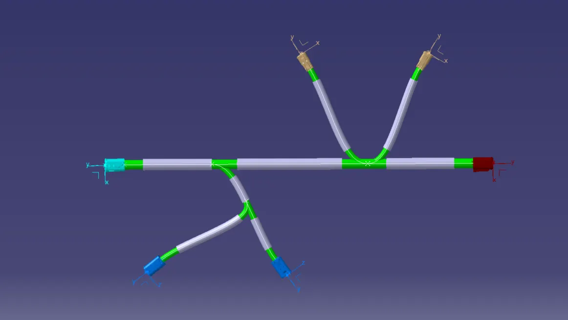
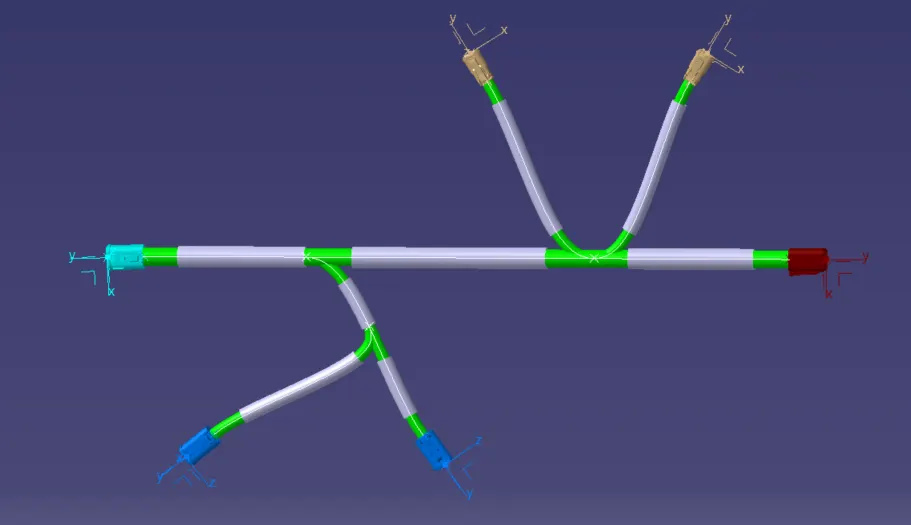
After positioning of the connectors in the respective positions routing can be done, following the electrical harness assembly workbench command called MULTI-BRANCHABLE , where you can define the branch defination.The path is selected between the selected connectors, we can alter the path of routing by changing or defining the path by various possible outcomes of tools like tangency, exterior path,automation with clearance etc.
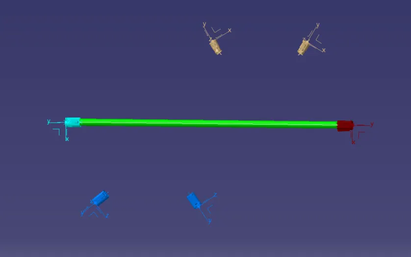
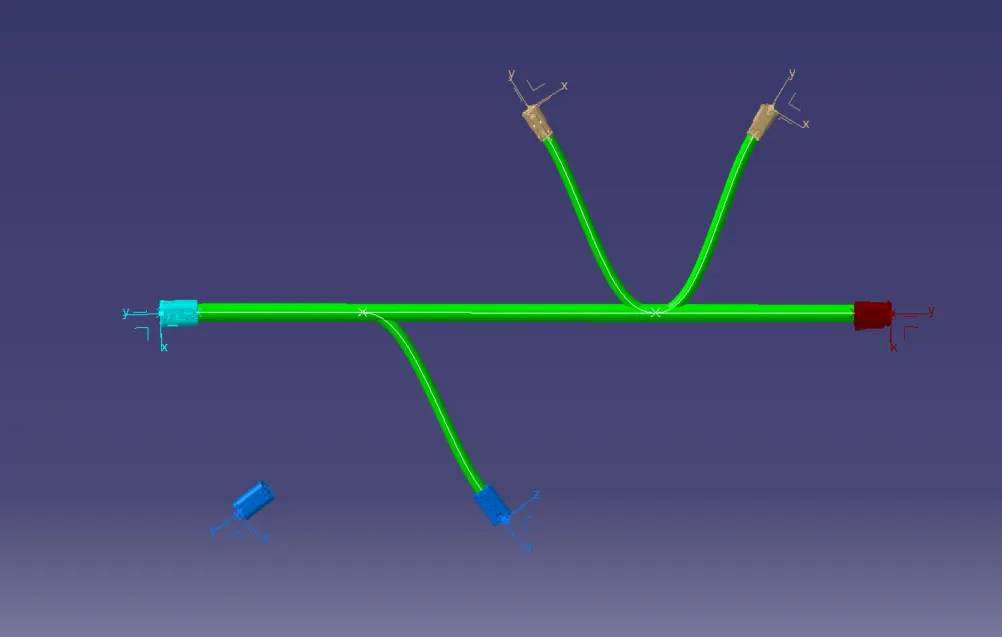
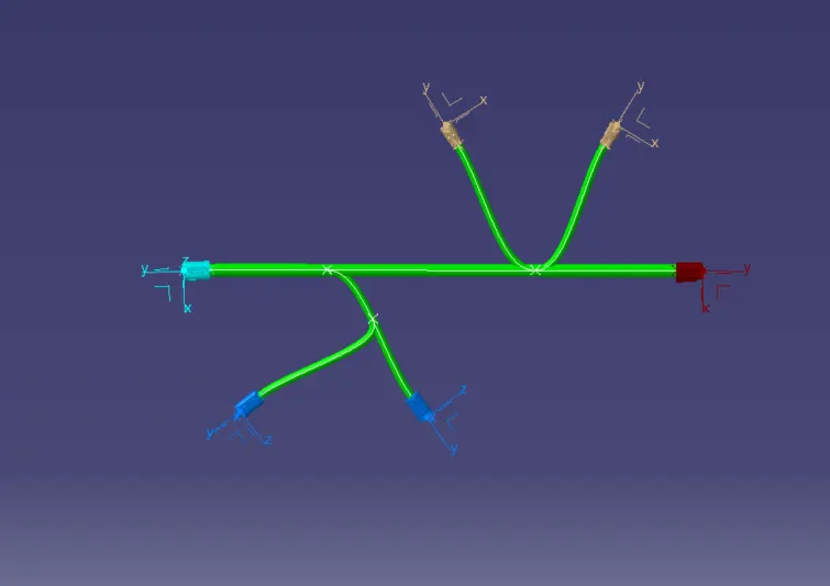
Protective covering on all branches connected to connectors
Step - 2:
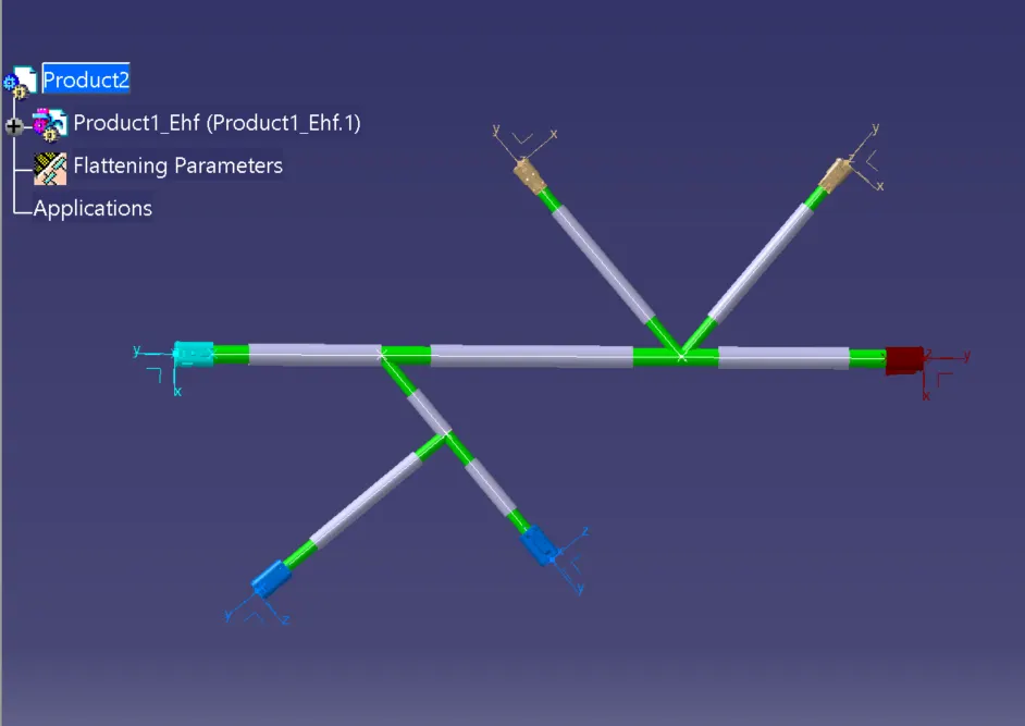
- Select the 'Extract' option from the Electrical Harness flattening workbench and select the Geometric bundle product in the wire harness assembly product file.
- Then wire harness assembly is imported to the Wire flattening product file with 'EHF' extension added to the geometric bundle assembly name.
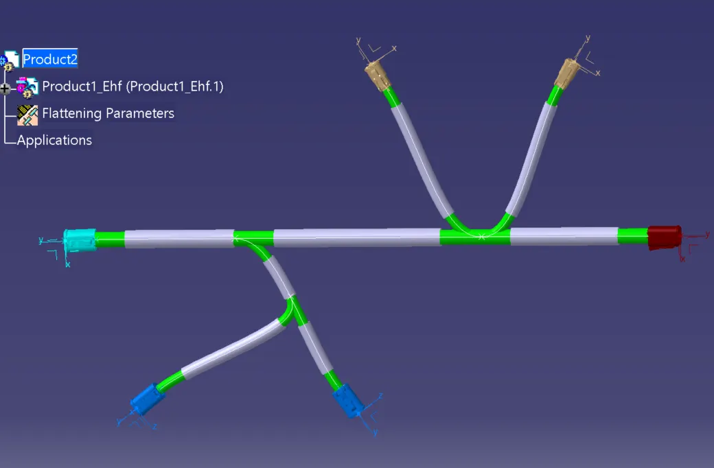
attened the electrical harness geometrical bundles by using flatten command
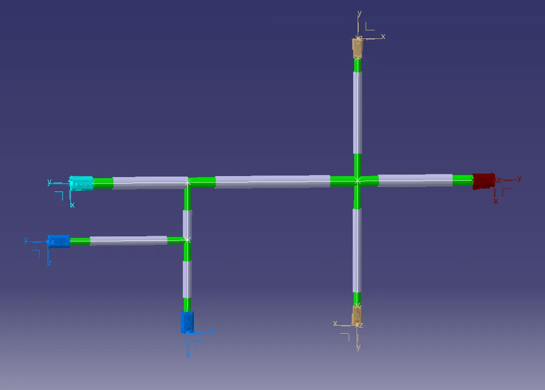
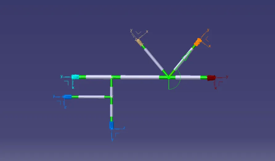
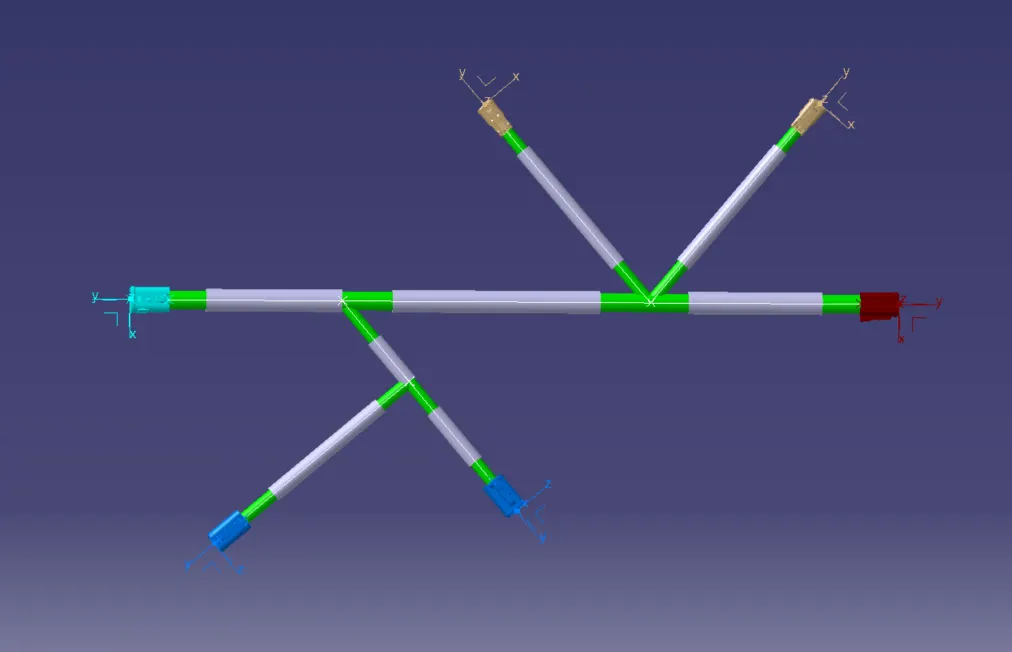
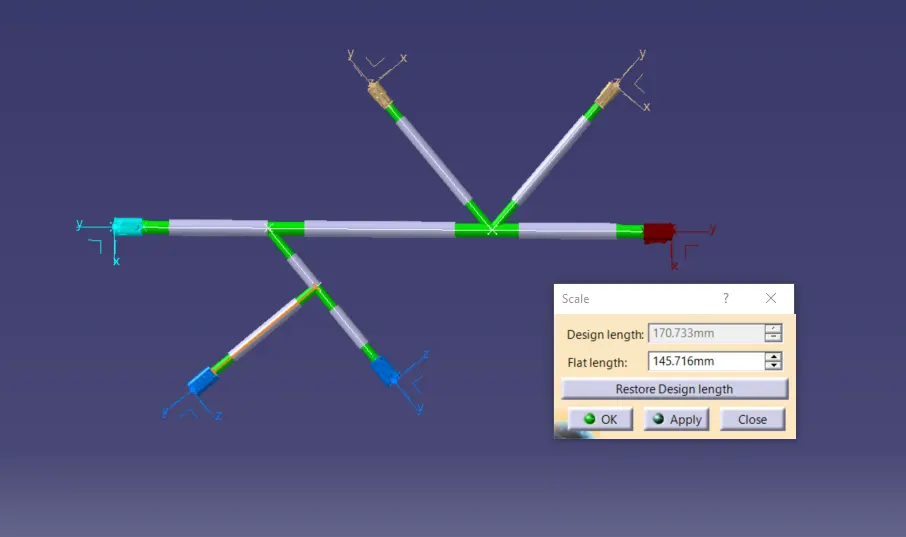
- Rotate the flattened bundle segments to the desired directions using the Rotate command and manually update the product to update the changes occurred during the rotate command.
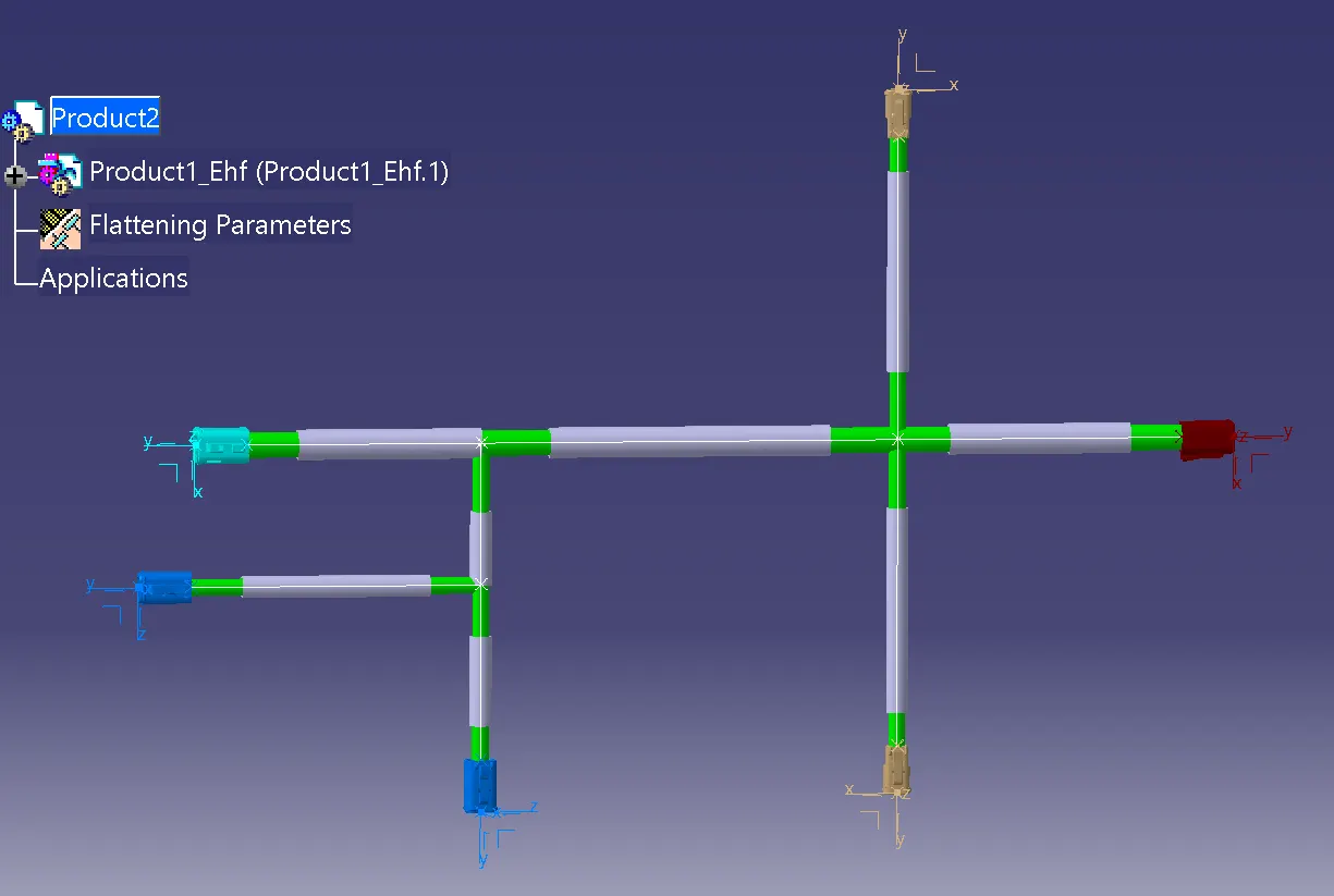
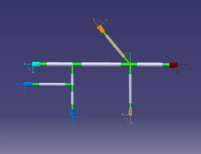
USE DIFFERENT COMMAND FOR ARRANGMENT THE DUNDLE-
PROVIDE ANGLE VIA ROTATE COMMAND-
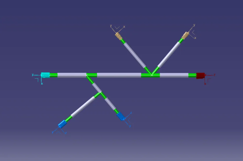
FOR DRAFTING:
Step - 1:
- Create a new drawing file and save the file in the same location.
Step - 2:
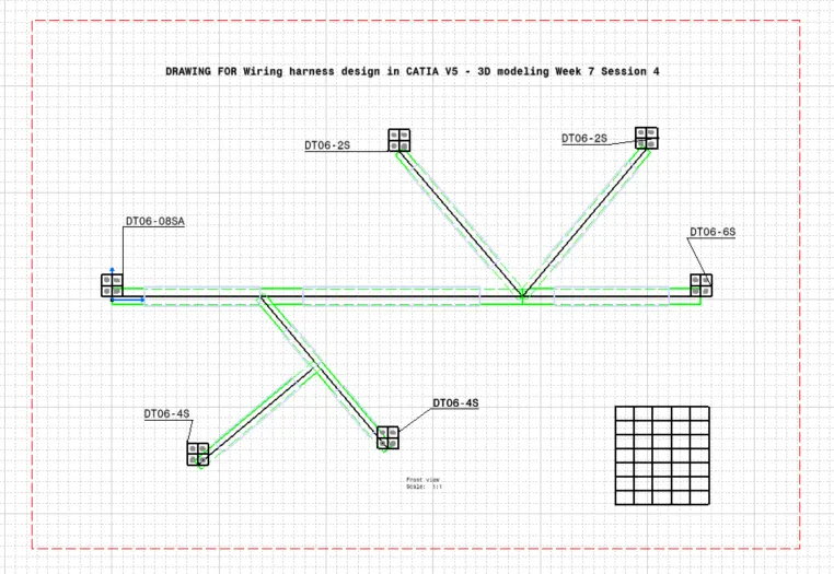
- Insert the title block template and fill up the required details.
Step - 3:
- Add the front view of the harness assembly by selecting any one of the flat faces of the connector and orient the view as per the requirement.
Step - 4:
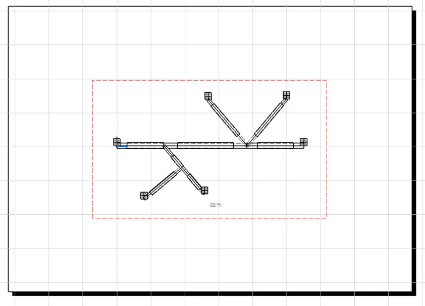
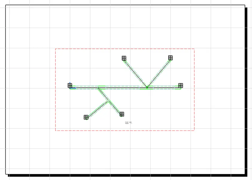
- Go to the properties of the view and select the '3D Wireframe' on and ' Is always visible' option in order to see properly the Wire bundle, connectors and the protection coverings.
Step - 5:
- Show and name all the parts used in the wire harness assembly in form of a table.
- Create a new drawing file in the drafting workbench
- Modify the drawing sheet with required parameters.
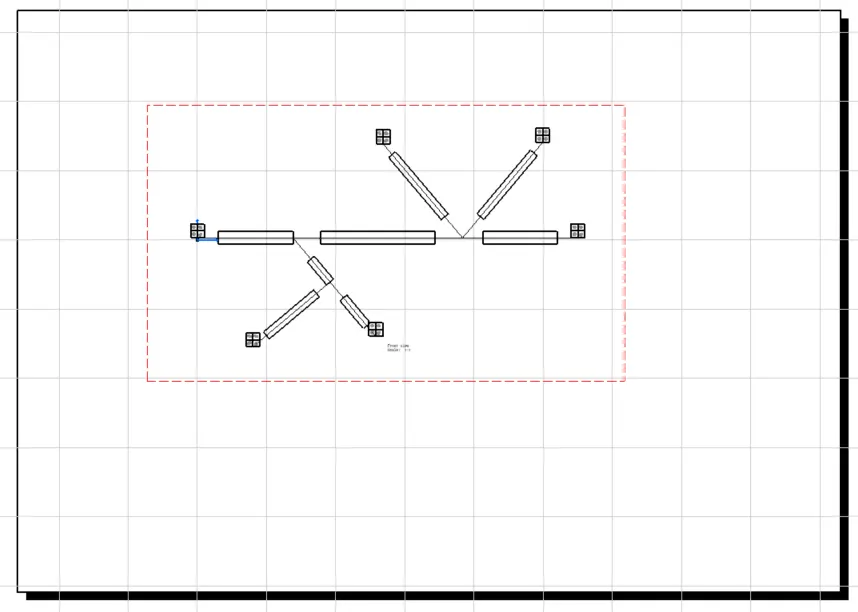
- Insert the flattened harness product into the drawing sheet using view option and selecting the front view command.
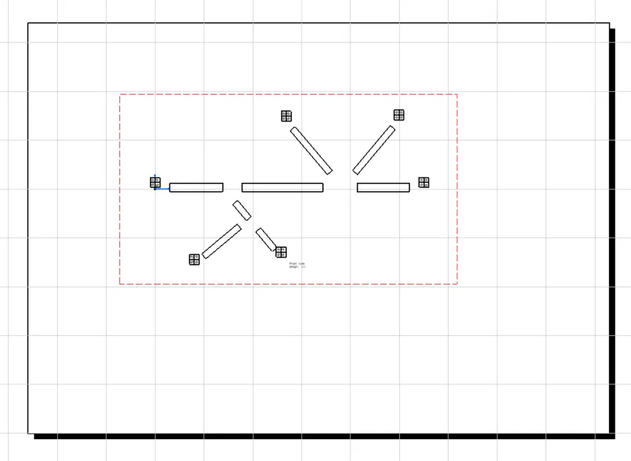
Created a drawing file and added the front view of the flattened wiring harness assembly
CONCLUSION:
- From the above assignment we learnt how to flatten a given wire harness assembly and how to place the flattened view on a drawing sheet and show all its components.
CAD AND DWAWING FILE ARE ATTACHED
THANKYOU ....