Week 1 Stress Concentration on a Plate with hole
Aim: The motive of this challenge is to conduct stress analysis on two different types of structural steel plates, one with a hole in the center and the other with 3 holes as given in the cases. The load conditions for both the cases will be the same .i.e. one side will be fixed and the other side is subjected to a force of 500N.
Procedure:
Geometry: The geometry is made using SpaceClaim according to the given dimensions in the cases. We use the pull feature to create the holes in the bar.
Mesh:
- Set the default mesh size to 3.5mm.
- Then add a mesh method to the entire body. The mesh method is tetrahedrons.
Analysis Settings:
- This only a 1-second analysis.
Load Conditions:
- Right click static structural > select fixed > select the left face.
- Right click static structural > select force > select the right face > add a magnitude of 500N.
Solutions:
- Right click solution > select stress > select Von-Misses Stress.
- Right Click Solution > Select deformation > total deformation.
Results and Discussion:
Case 1:
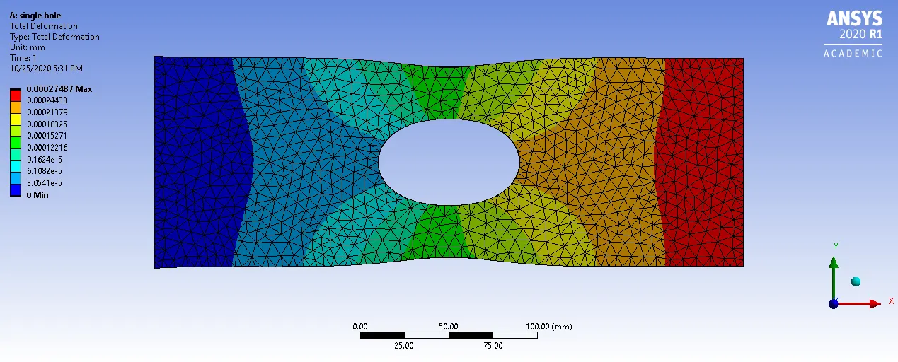
As a force is applied in a direction normal to the right surface it experiences a deformation in the x-direction. As the right region is closest to the force applied it experienced the most deformation. The maximum deformation experienced is 2.748e-04mm.
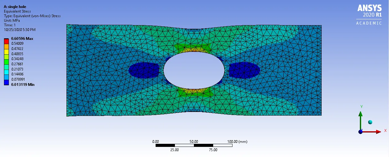
Following is the equivalent stress experienced in the plate. It can be observed that the top and bottom region of the hole experiences the maximum stresses. Note that these are exaggerated reports of contours. The maximum stress is 0.605 MPa and the minimum is 0.013 MPa.
Case 2:
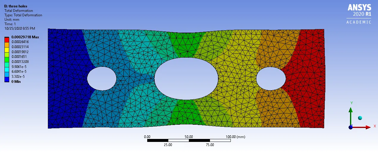
Similar patterns of deformation are obtained in the plate and the maximum deformation experienced is 2.971e-04mm.
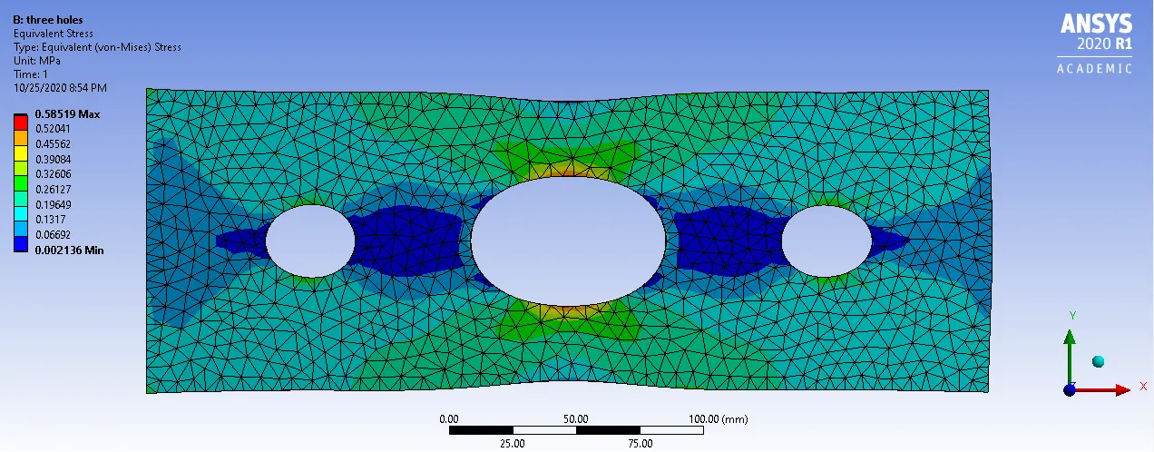
Here too the stress concentration is in the top edges of the center hole. For the smaller holes, the stress concentration is high at the top and bottom but not as high as the center hole. The maximum stress is 0.58519 MPa and the minimum is 0.00213 MPa.
Comparison:
Following is the Maximum, minimum, and average values of the von-misses stress and deformation experienced in both cases. Here we observe that maximum & average stress is more for case 1 whereas the maximum & average deflection is more for case 2.
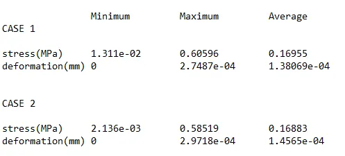
Analysis Stand Point: From the analysis perspective I would select the 2nd case as it experiences less maximum stress. Also, from the contour, we notice in case 2 that the region of lower stress areas is greater compared to case 1.
Manufacturing Stand Point: From a manufacturing perspective also I would choose the second case as it uses less material volume. If the same workpiece is going to be manufactured on a large scale then it would lead to a significant reduction in the cost of manufacturing as less volume of material is used.