Week 3 Verification of Weld Joints
Aim: To conduct stress analysis on weld joints made using different materials.
Procedure:
Materials: Go to engineering data and add the new materials required for different cases. Such as case 2 we need copper Aluminium alloy and for case 3 we need brass and copper.
Geometry: Open space claim and drag the geometry into it.
Setup:
Components: The welded assembly has different components, assign names to them .i.e. weld, ribs, small plate, and large plate. The materials for these elements are assigned here as provided in different cases.
Connections:
- Contact: There is a bonded contact between the welds and the ribs/plates. Whereas, there is a frictional contact between the small plate, large plate, and ribs.
Mesh: Default mesh is applied to it as it is best in the current scenario.
Analysis Settings:
- Number of time steps: 1
- Auto time step: Program Controlled
Load Settings:
- The fixed load is applied to the 4 holes of the large plate.
- The force of 150000 N is applied to the rectangular hole of the smaller plate in the downward direction (here +Y direction).
Solution:
- Directional deformation for the whole setup is obtained.
- The equivalent strain for the entire setup is obtained.
- The von mises stress for only the weld elements is obtained and then the welding element experiencing maximum stress is noted.
Results & Discussion:
Case 1:
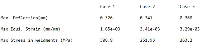
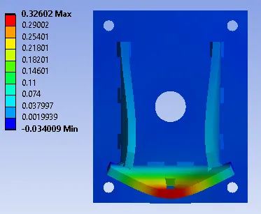
In this case, we the ribs, plates, and weldments all made up of stainless steel. the maximum deformation is seen at the center of the closer end of the small rib. This deformation is 0.32mm
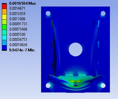
The maximum strain value is the assembly is 0.0016 mm/mm. If we observe then the stress in the hole of the small plate is observed to be high at the corners.
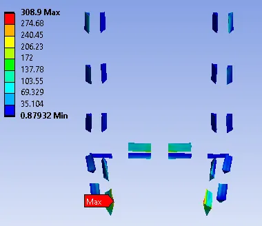
To find the maximum stress in the weldments a probe is used. In the given picture we can see that the maximum strain is experienced at the closer weldment between the small plate and left rib.
Case 2:
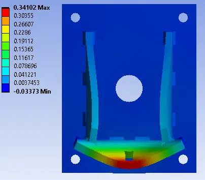
Here the weldments and ribs are made of aluminum but the plates are stainless steel. Similar deformation is observed in this case and the value of this deformation is 0.34mm.
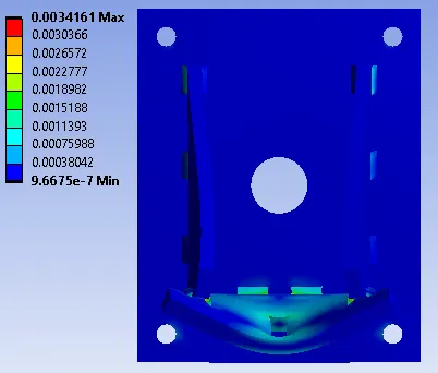
The maximum strain is observed to be of the magnitude 3.41e-03 mm/mm.
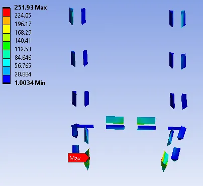
The maximum stress located at the same spot and weld, and in 251.93 MPa.
Case 3:
Here we observe Brazing. To do so the weldments are made of bronze, the plates are steel and the ribs are copper.
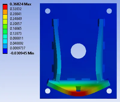
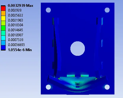
Maximum strain is 3.29e-03 mm/mm.
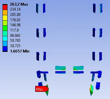
Maximum Stress is in the same weld. It is 263.2 MPa.
Conclusion:
The structural analysis for the three was done successfully and the following results were obtained. Here it is seen that the aluminum welds undergo the least stress and stainless steel the most.