Week 2 Railwheel and Track
Aim: To conduct an analysis of the rail wheel and track setup. Here we have two cases, one we will be applying 100000 N bearing load and for the other case we will be applying 500000 N.
Procedure:
Materials: Here all the materials are structural steel and as that is the default materials we don't need to add any extra materials.
Geometry: The geometry for the setup is dragged and dropped in Space Claim. Then is checked for any coincident surfaces or any other error.
Setup:
Connections:
- Contacts: First we rename the contacts according to selections
- A frictional contact is added between the rail and the wheel. Here the coeff. of friction is 0.3.
- Another contact is added between the shaft and the wheel and that contact is frictionless.
- Joints:
- A fixed joint is added at either end of the rail. This is a Body to ground joint.
- A translational joint is added to the shaft that holds the wheel. This translation should be in the X-direction. This is also a body to ground joint.
- Another joint is added on the wheel, which is a planar joint. This is added to the rear of the wheel.
Mesh:
- A mesh sizing is provided on the surface of the rail and the wheel, the surfaces that will be in contact. The size of the mesh is 35mm.
- The rest of the body will have a 50mm mesh size.
Analysis Settings:
- Number of time steps: 5
- Auto time-stepping: ON
- Define by: Time
- Initial time step: 0.1s
- Minimum time step: 1e-003s
- Maximum time step: 1s
- Solver type: Direct
- Large Deflection: On
- Force convergence: On
- Turn on All output controls.
Load Settings:
- A bearing load of 100000 N is added in the first case at the inner face of the wheel, and in the 2nd case, it is 500000 N. This load is in a negative y-direction.
- A joint displacement is added to the translational joint with an increment of 100 mm every second for 5 seconds.
Solution: Equivalent stress and life for both the load cases are obtained and compared. For the 2nd part of the question, we need to write an expression to calculate the total deformation in the 500000 N load case and see if it is the same with the 100000 N load case.
Results & Discussion:
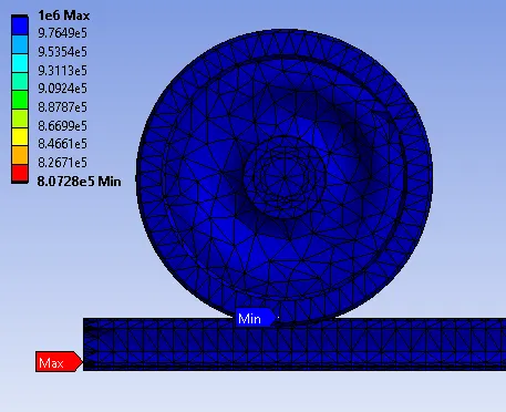
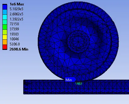
The sequence of the image is 100000 N > 500000 N
Case 1:
For a 100000 N bearing load, we observe maximum stress of 163.75 MPa and for 500000 N bearing load it is 708.27 MPa. Whereas at the end of 5s the stress is 89.46 MPa and 400.26 MPa respectively. If we notice carefully then the stress experienced by the 500000 N bearing load case is almost 5 times the other along with that the location of maximum stress is the same for both the cases.
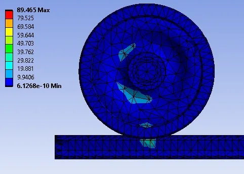
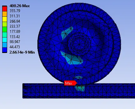
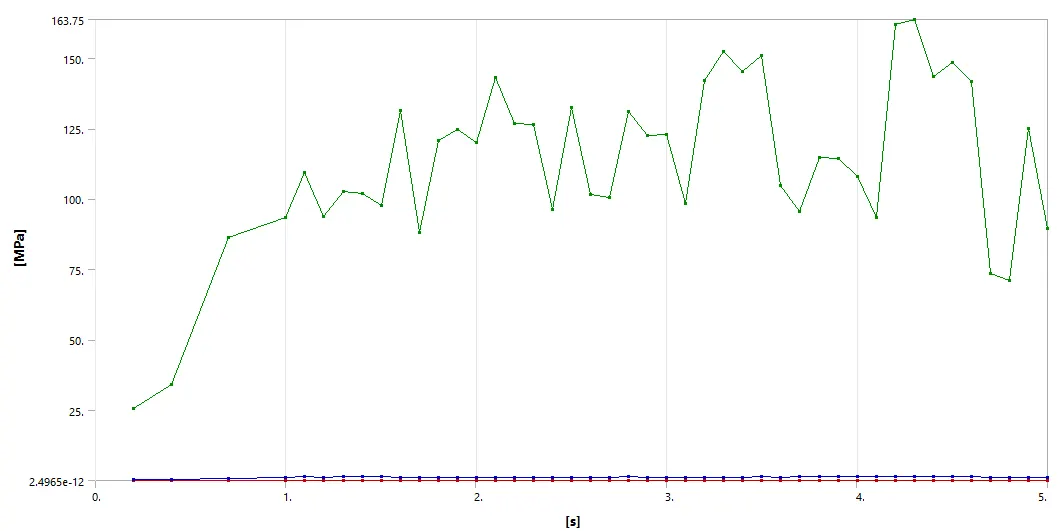
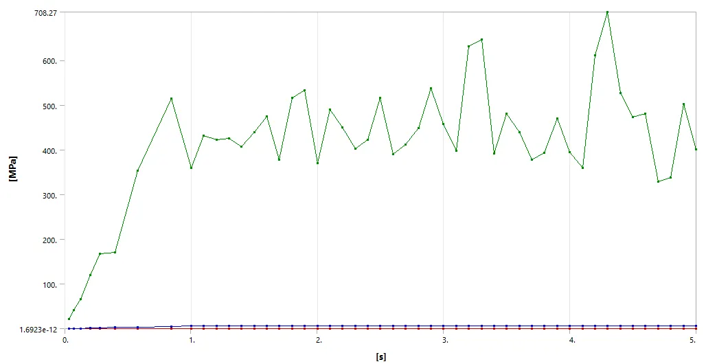
As the stress increases the minimum life of the setup also decreases and that is what we have obtained in the simulation. The life of 500000 N bearing load has significantly decreased as the stress experienced by it is significantly increased. The minimum life for a 100000 N case is 8.07e+05 cycles whereas for the other it is 2698.6 cycles.
Case 2:
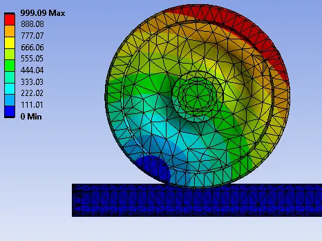
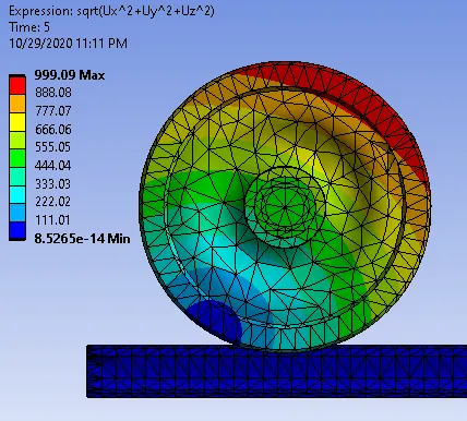
The total deformation for both the load cases remains the same as it depends on the applied boundary conditions. the expression used to calculate total deformation is the larger load case is [sqrt(Ux^2+Uy^2+Uz^2)]. Also, both contours are the same.
Conclusion: The structural analysis of the rail wheel and track model for 100000 N & 500000 N was successfully conducted and it is found that the life cycle for the larger load case significantly decreases however the displacement in both the cases remains the same.