Week 8 Worm Gear Challenge
Aim: To conduct a worm gear assembly transient structural analysis.
Procedure:
Geometry: Drag and drop the geometry in space claim to upload it.
Setup:
Components: Name the components as worm and gear. Both materials are structural steel.
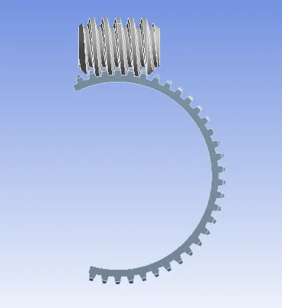
Connections:
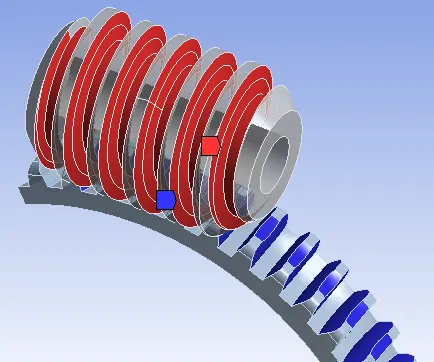
- Contact: Assign a frictionless contact between the worm teeth and the gear teeth. Set the interference treatment as adjust to touch.
- Joint: Assign body to ground revolute joints to both the worm and the gear.
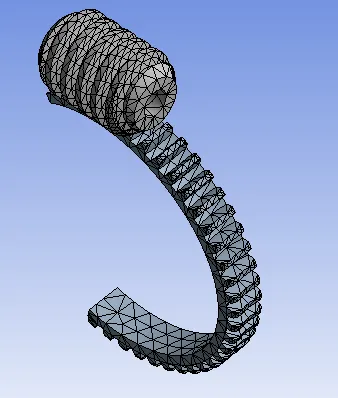
Mesh: Use the default mesh and make sure that adaptive sizing is on. This is done to increase the nodes in the gear teeth.
Analysis Settings:
- To make the movement of the worm to the half end of the gear we make 90 steps.
- Turn on auto time stepping and define it by time.
- For the first step, the initial time step is 0.2s, the minimum time step is 0.2s, and the maximum time step is 0.5s.
- From 2 to 90, turn on the carryover time step and set the minimum time step as 0.2s, and the maximum time step is 0.5s.
- Make sure to turn on large deformation.
Load Settings: Add a joint rotation load to the worm joint. With an increment of 75 degrees at every time step till the 90s.
Solution: Contours and plots of equivalent stress, equivalent strain, and total deformation is obtained.
Results & Discussion:
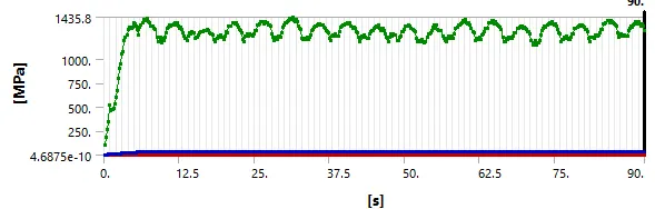
Equivalent Stress: The maximum equivalent strain experienced is 1301.5 MPa and this is at the interface between the middle teeth of the worm and the gear.
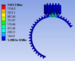
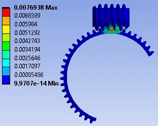
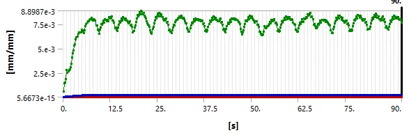
Equivalent Strain: The maximum equivalent strain experienced is 7.69e-03 and this is at the interface between the middle teeth of the worm and the gear.
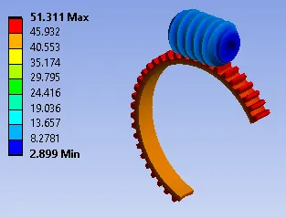
Total Deformation:
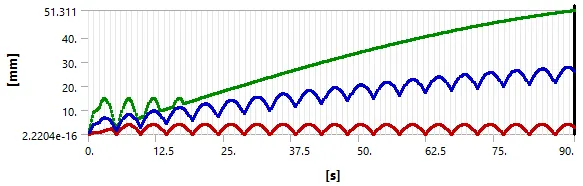
Conclusion: The transient structural analysis of the worm gear was successfully conducted. It can be inferred that the maximum stress and strain is always observed at the middle teeth of the worm gear interaction.