Gate Valve Parametric Study
Objective: To perform a parametric study on a gate valve to calculate the mass flow rate, flow coefficient, and flow factor for the gate valve opening from 10% to 80%.
System Approach: The gate valve design is uploaded in space-claim. An enclosed volume is created, covering the fluid volume. The gate in the design is moved in the respective upward direction, and that is set as the parameter set. The setup is run using a standard k-epsilon viscous model.
Pre-Processing: Open Ansys and drag fluent on to the project window. Then open geometry.
Geometry:
- Go to design > select move > then select one side of the pipe and move it by 500mm > do the same for the other side.
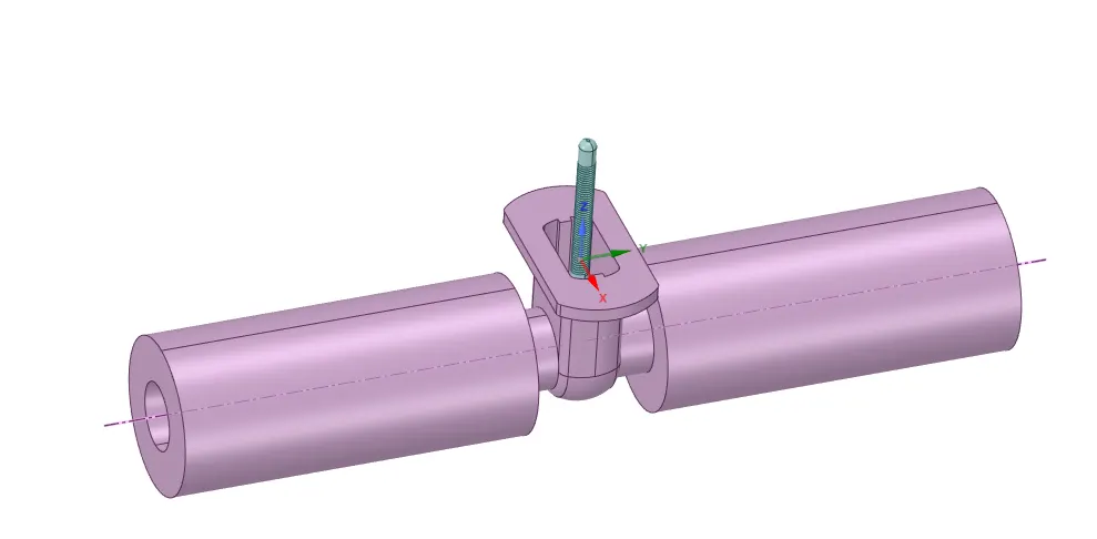
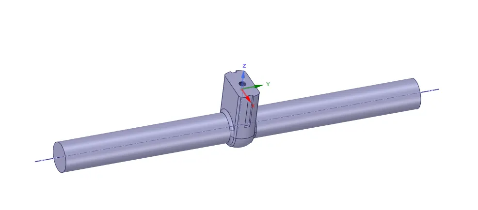
- Then go to prepare> select enclosed volume > using edge selection select the edges > create enclosure.
- Suppress all the parts of the initial design.
- Then go to design > select move > select the gate component > drag to the respective perpendicular direction > then set as 10 and click P to set the parameter. This parameter will be created in groups.
- Right-click on the enclosed volume > select update as in context.

Mesh:
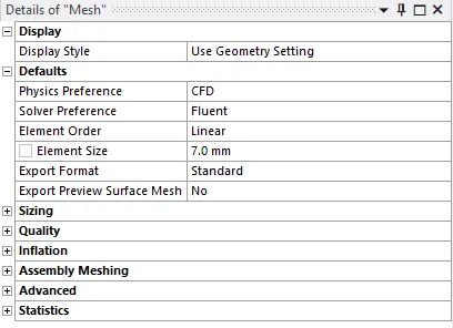
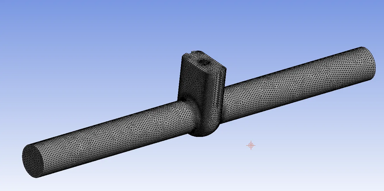
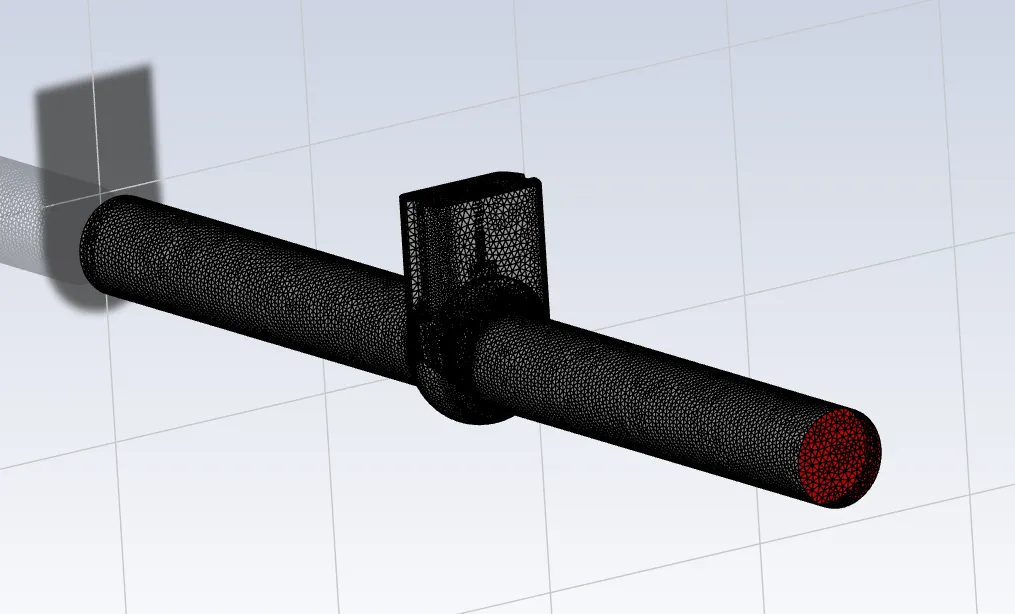
After the geometry has successfully been uploaded to the meshing module. Create named selection of inlet and outlet. Then create a fine mesh by reducing the element size in the mesh option.
Setup:
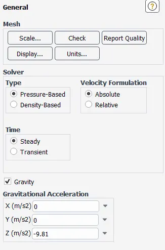
- It is a steady-state, pressure-based solver. Ensure that gravity is turned on, in this case, it will be in the negative Z direction.
- In the model, > set viscous model to standard k-epsilon and wall-function must be scalable.
- Create a new material, which is water.
- In cell zone condition change the material to water-liquid, then delete the initial material, air.
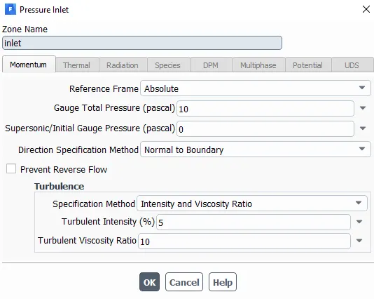
- Change the boundary condition of the inlet to pressure inlet and set the guage pressure to 10 Pa.
- In method > change it to simple and set all of it to first-order upwind.
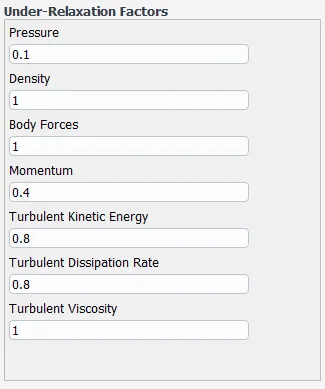
- Go to controls and set the relaxation factors as given:
- Go to initialization > select standard hybridization > compute from inlet > initialize.
Solution: The required solutions are: the value of mass flow rate, and velocity contour (for the first case).
- Go to solutions > derivatives > flux report > mass flow rate > select outlet > create report plot and output parameter.
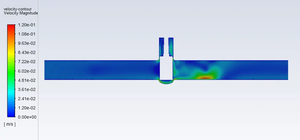
- Create a YZ-plane at the x=0. Set a velocity contour on the plane.
- Compute for 250 iterations.
- The exit setup. Go to the parameter set > add different input parameters for gate valve height 20mm, 30mm, and so on.
- Then select all the new parameter > right-click > select update selected sets.
Result and Discussion:
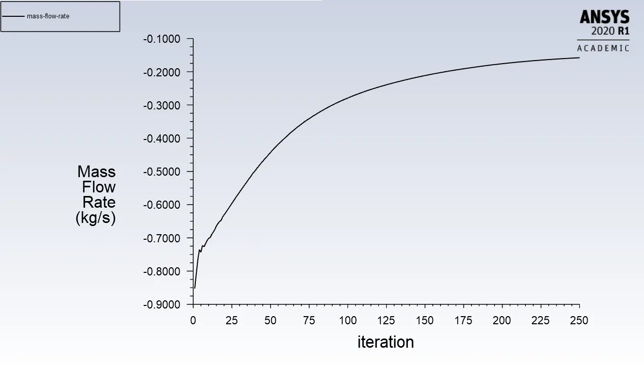
10mm:
The plot for mass-flow rate is:
The velocity contour is:
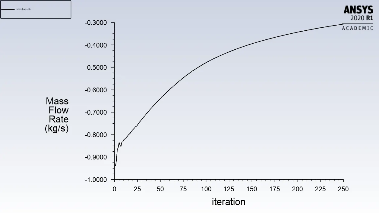
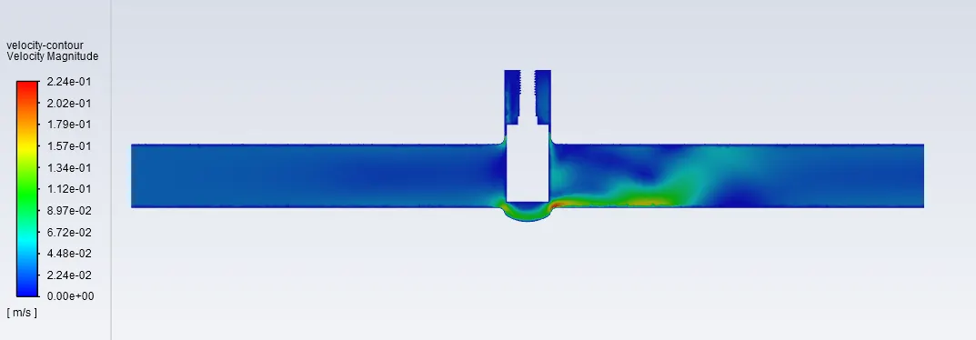
20mm:
The plot for mass-flow rate is:
The velocity contour is:
30mm:
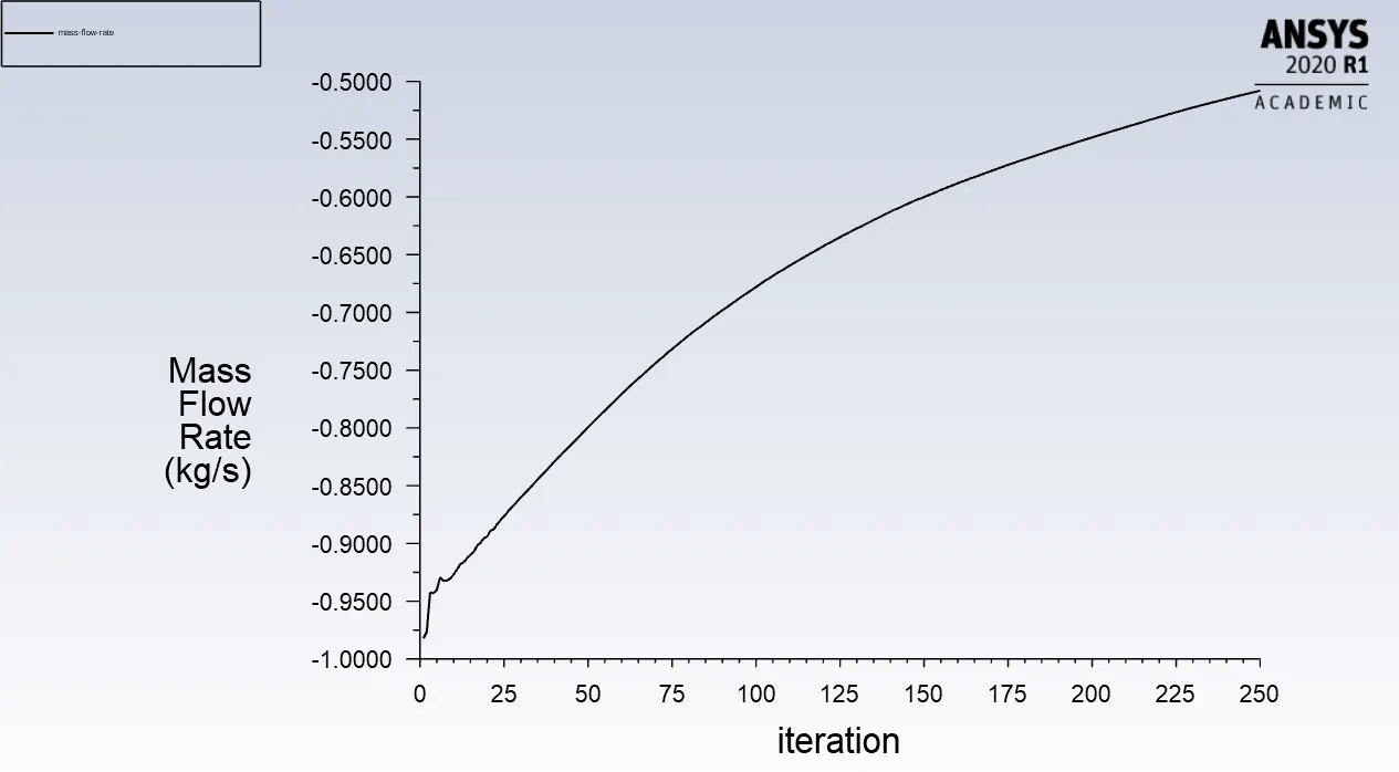
The plot for mass-flow rate is:
The velocity contour is:
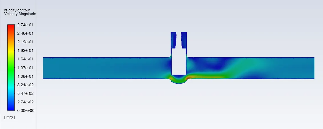
From the above plots and graphs, we can observe that the mass flow rate at the outlet increases as the gate height is increased, which shows that the obtained results are correct.
The value of mass flow rate obtained at the end of the solution is:
- 10mm gate height: -0.1578 kg/s
- 20mm gate height: -0.3073 kg/s
- 30mm gate height: -0.5079 kg/s
Here the negative value shows that the mass flow is in an outward direction.
To calculate the flow coefficient we use the given formula:
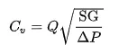
where,
Q = flow rate in gallons/minute
SG = Specific gravity. That is 1 for water.
delta P = pressure drop across the valve in psi.
To calculate the flow factor we use the given formula:
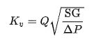
where,
Q = flow rate in m^3/hr
SG = Specific gravity. That is 1 for water.
delta P = pressure drop across the valve in bar.
The relation between the two is given by:-
Flow Factor = 0.865 Flow Coefficient
Therefore using appropriate calculation the flow factor and flow coefficient is given in the following table:

So we notice that the flow coefficient and the flow factor increases with the increase in gate height which is true as the mass flow rate increases also increase.
Thus the parametric test is successfully conducted for a gate valve.