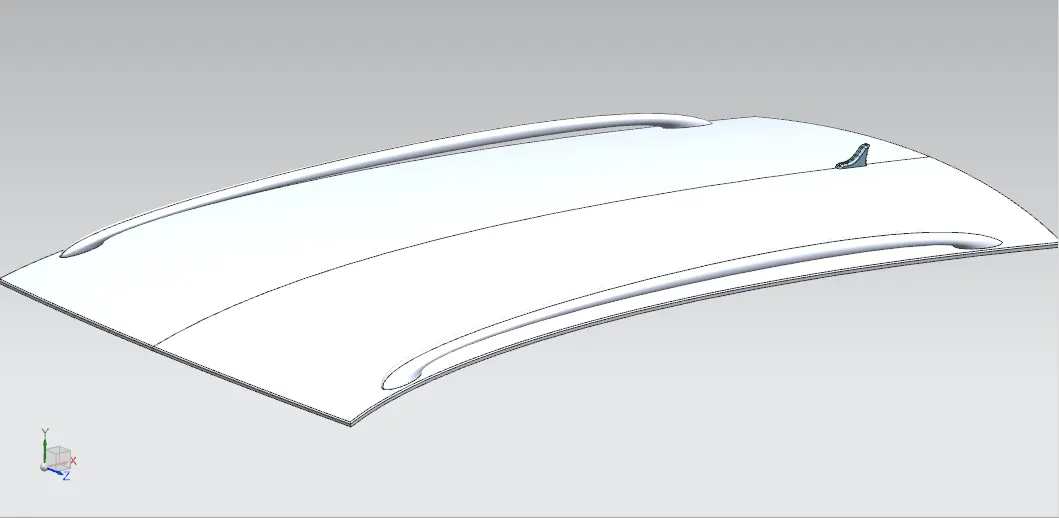
Roof Design
PROJECT - ROOF DESIGN WITH REINFORCEMENTS
IN THIS REPORT- GIVEN DATA
- INTRODUCTION OF ROOF AND ITS TYPES
- BENCHMARKING - REINFORCEMENTS
- DESIGN OF ROOF AND REINFORCEMENTS
- HEAT DISTORTION AND SNOW LOAD CALCULATION
- DRAFT ANALYSIS
- DESIGN AND PRODUCT VALIDATION VIA DIFFERENT TYPES OF TESTS
- MANUFACTURING PROCESS
GIVEN DATA
SKIN DATA
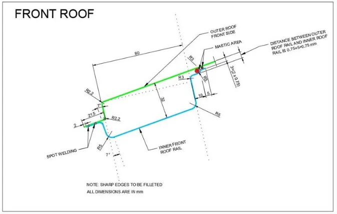
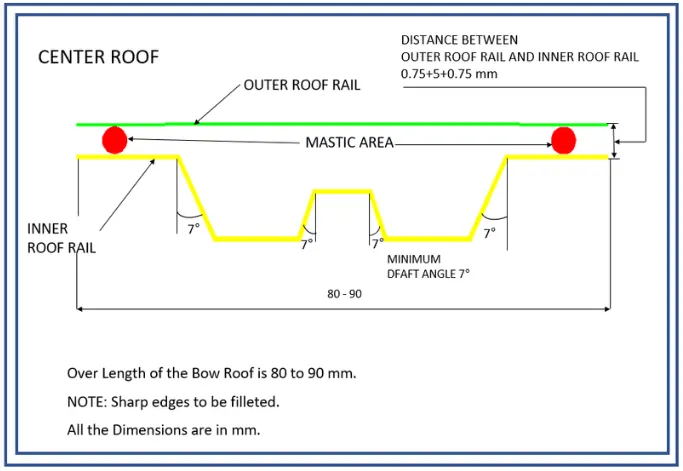
MASTER SECTIONS
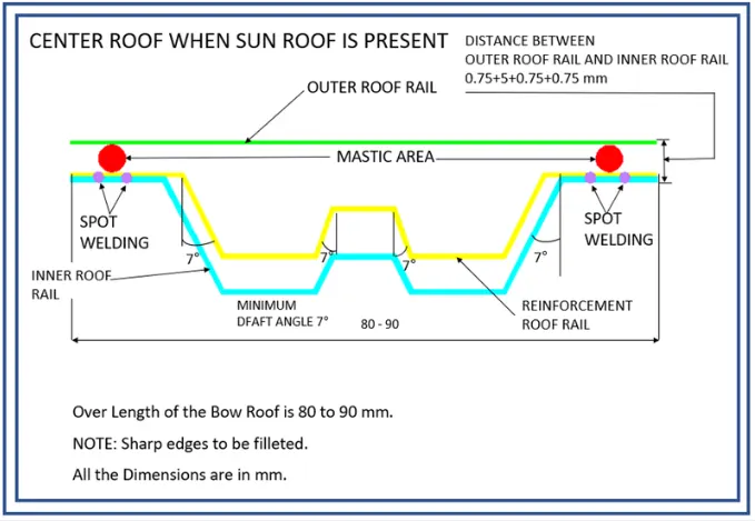
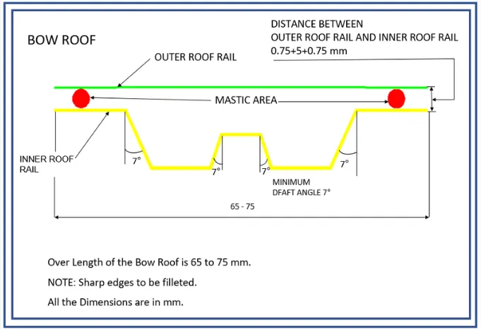
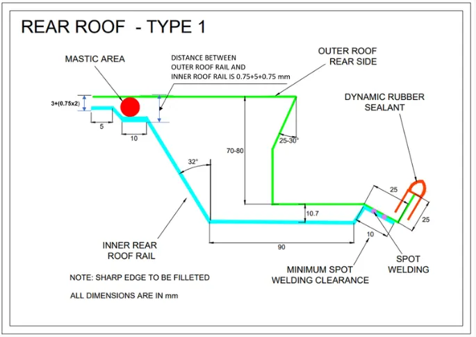
INTRODUCTION OF ROOF AND ITS TYPES
ROOF
- An automobile roof or car top is the portion of an automobile that sits above the passenger compartment, protecting the vehicle occupants from sun, wind, rain, and other external elements.
TYPES OF ROOFS
- Convertible Roofs
- Hardtops
- Sunroofs
- T-tops
- Targa tops
- Vinyle Roofs
KEY HIGHLIGHTS
- Sunroofs have become highly desirable in modern cars, even in affordable models like compact hatchbacks and SUVs
- The term “sunroof” is often used generically, but there are actually different types of glass roof panels available in cars
- While the presence of a glass panel on the roof is generalized as a sunroof, there’s more element to the story. There are multiple types of sunroofs available in cars nowadays, and people often mistake a moonroof for a sunroof. Here, we have described the differences between different types of glass roof panels in cars sold in the modern era:
SUNROOF
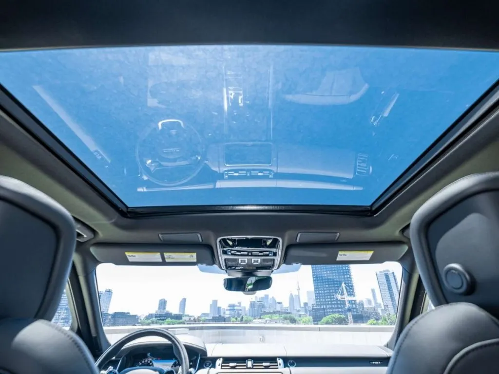
- Contrary to what most people believe and even what carmakers promote nowadays, a sunroof is essentially an opaque panel. This panel is present on the roof of the vehicle, which matches the color of the vehicle and can be either tilted open or taken off wholly.
MOON ROOF
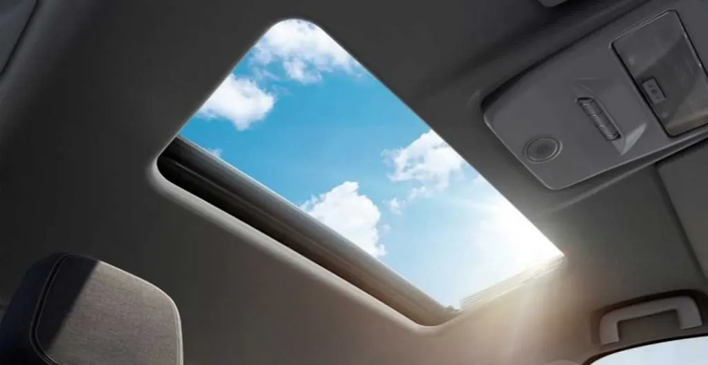
- It is the actual sunroof that matches the perception of most people. It is also a type of sunroof, but it is a glass panel present on the roof of a vehicle. This glass panel can tilt open or slide between the roof panel and the headliner of the vehicle. For added protection and aesthetics, a moonroof also comes with an additional sliding panel. Almost all modern cars now come with a single-pane or a panoramic moonroof. An example of a car with a moonroof is the new 2022 Brezza.
PANAROMIC ROOF
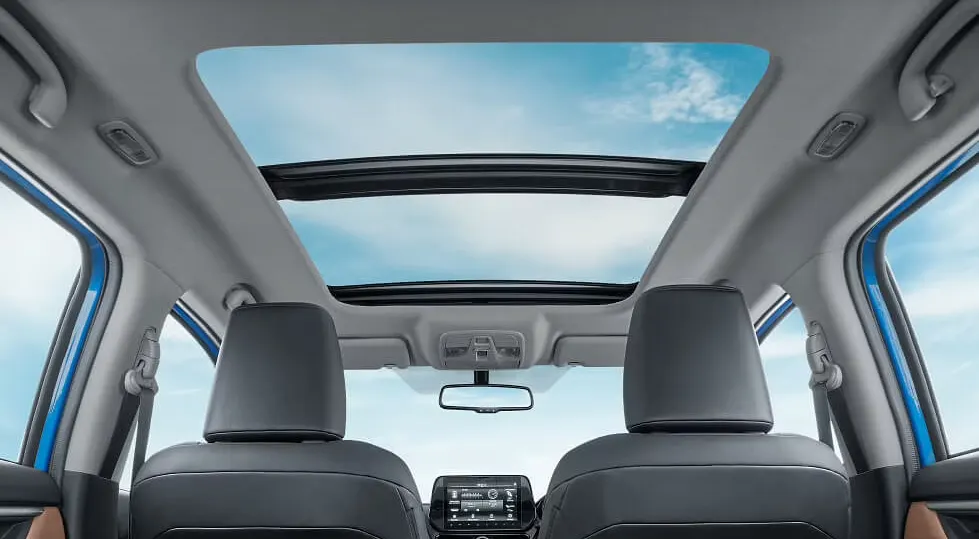
- While some carmakers are yet to offer a single-pane sunroof in their popular models, a few have edged ahead by offering panaromic roof. As the name suggests, a panoramic sunroof gives a panoramic view of the skies above. It is possible by a larger glass panel covering more than half of the roof panel. An example of an SUV with a panoramic sunroof is the Tata Harrier.
- This glass panel generally has two halves. While the glass panel above the front row can slide and open, the other half glass panel above the rear rows has a fixed design. However, in some cars, there is a single large glass panel as a panoramic unit, which partially slides or opens up. A panoramic unit is more effective in making the cabin feel airier and brighter when compared to a single-pane sunroof.
- In recent times, SUVs like Hyundai Creta, MG Hector, and Mahindra XUV700 have popularized the concept of panoramic sunroofs. Single-pane sunroofs have made their way in most sub-compact SUVs and even hatchbacks like the Hyundai i20 and Honda Jazz.
BENCHMARKING - REINFORCEMENTS
FROM INTERNATIONAL MARKETS
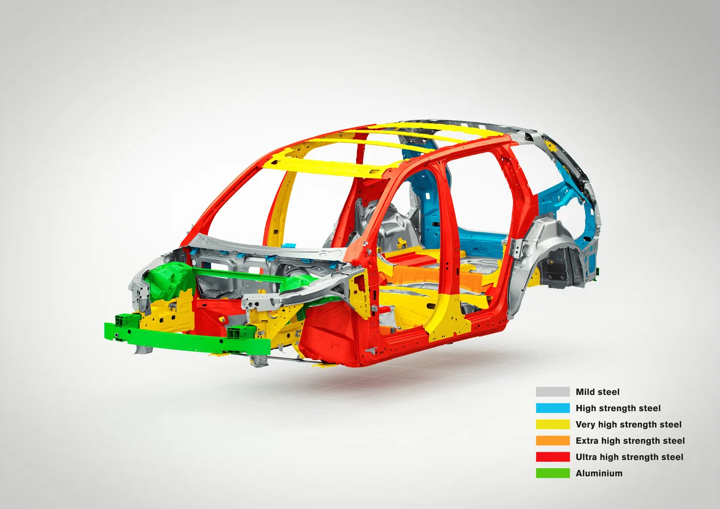
VOLVO XC90
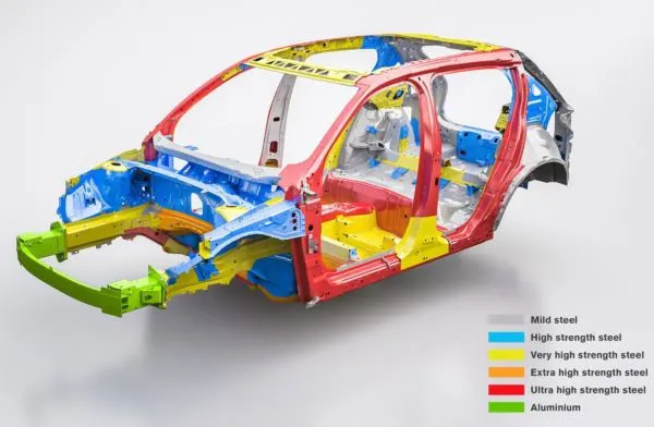
VOLVO XC40
BMW X5
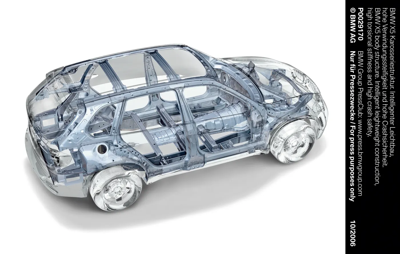
FROM INDIAN MARKETS
TATA SAFARI
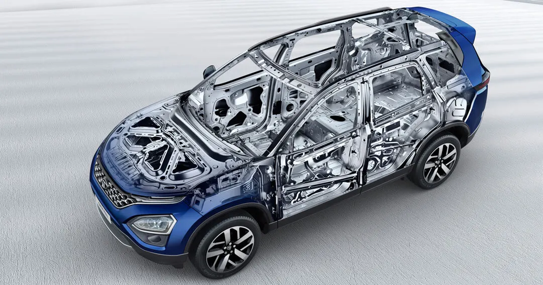
SUZUKI ERTIGA
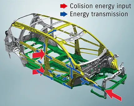
- There is, i only compare the a visual designs of the BIW models. according to these models center bow is positioned and connected with the B piller and center bow flange is wider in the models. so i took design inspiration from the benchmark.
DESIGN OF ROOF AND REINFORCEMENTS
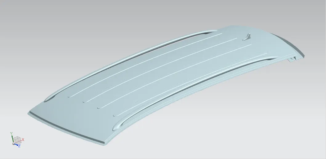
ROOF DESIGN
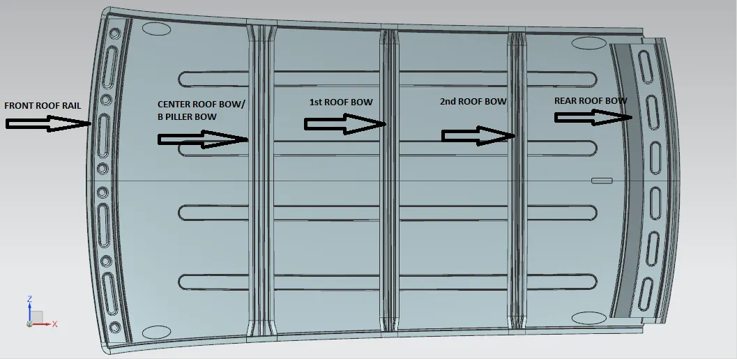
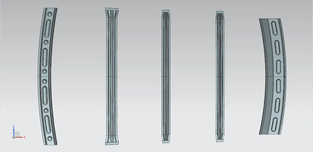
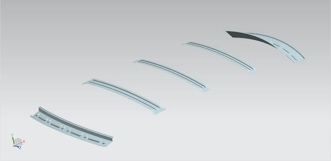
- Roof is not a single element, it consists of Front roof rail, Rear Roof Rail, Bow Roof Rail, Center Roof Rail. These Bow Roofs are placed in the most Flat area of the Panel. Rear Roof Rail joins with the Back door and Body side outer. Front Roof Rail joins with the Wind shield glass and body side. Here are some reinforcement used in the Roof.
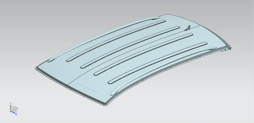
EMBOSSES CREATION
- I add the Embosses on the roof outer panel, front roof rail and rear roof rail for the purpose of oprtimizing the parts strength without adding the extra material thickness.
- Thickness of all parts are 0.75 mm
ROOF OUTER PANEL
FRONT ROOF RAIL
- This will be a supporting room lamp for some cars. It is contacted and connected with wind shield and car body , a pillers of both side. We need to consider the Visibility criteria line for designing Front roof rail.
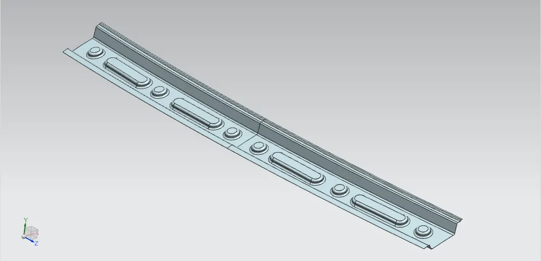
POSITIONING OF BOW ROOF:
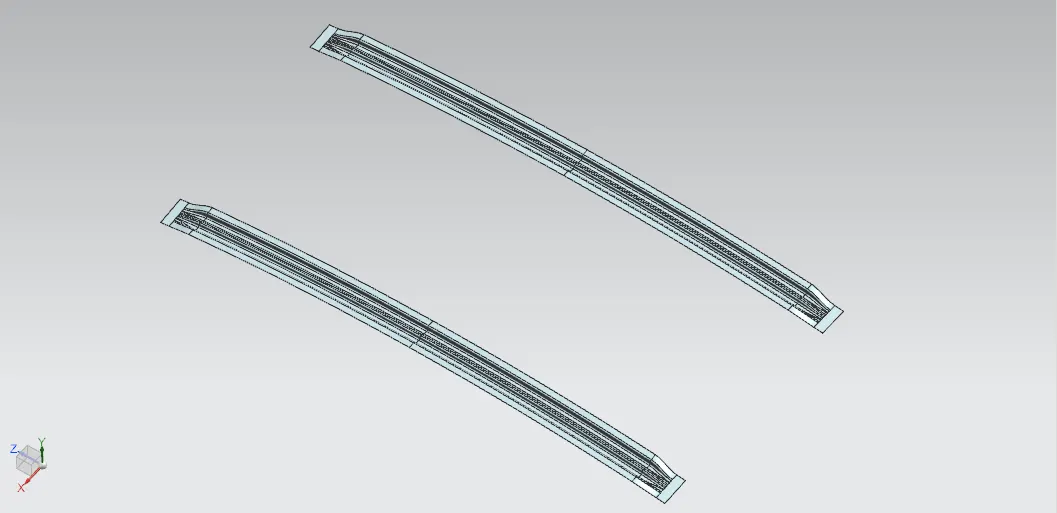
- The bow roofs are given to improve the torsional stiffness and load bearing capacity of the roof structure .The number of bow roof present depends on the overall size of the roof . Presently I have added two bow roofs.
- Centre roof rail helps in providing effective support to the flat area of the roof as it is more susceptible to failure under the action of load. generally the center roof rail is placed at the center of the roof and is connected to the B-pillar structure.This helps in adding the strength to the roof during the rool- over test.
- I positioned the center bow after the front bow because of benchmarking. the center bow is strongest among the other bows, so i designed the center bow which will be connect with the B piller with the help of side roof rails inner panels.
CENTER ROOF BOW / B PILLER BOW
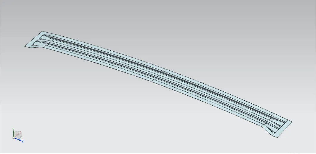
- Large flange design is optimised and inspired form the benchmarking.
1st & 2nd ROOF BOWs
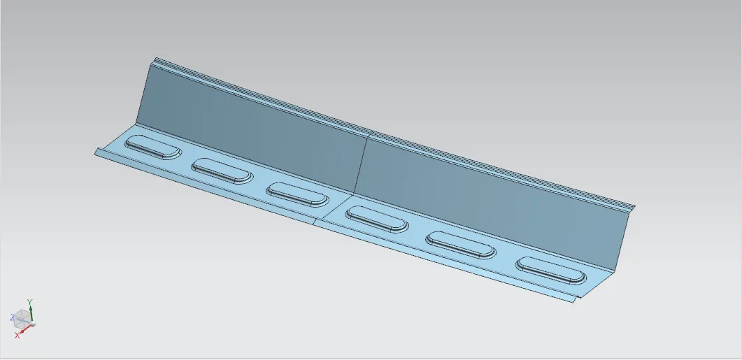
REAR ROOF RAIL
- Here we need to keep Head room clearance and rear view criteria for designing. Back door will be mounted here.It is contacted and connected with rear wind shield and car body , C or D pillers of both side
TOP VIEW
ISOMETRIC VIEW
HEAT DISTORTION AND SNOW LOAD CALCULATION
Y CROSS SECTION SKETCH - SIDE VIEW - OUTER PANEL
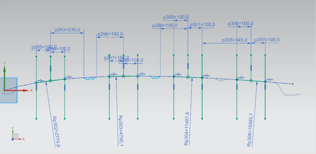
X CROSS SECTION SKETCH - FONT VIEW - BETWEEN FRONT BOW AND CENTER BOW - OUTER PANEL
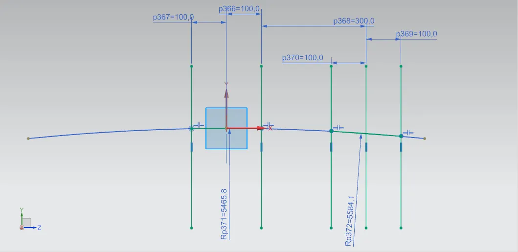
X CROSS SECTION SKETCH - FONT VIEW - BETWEEN CENTE BOW AND 1ST BOW - OUTER PANEL
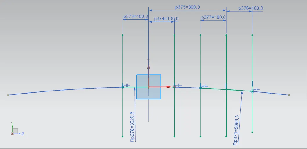
X CROSS SECTION SKETCH - FONT VIEW OUTER PANEL- BETWEEN 1ST BOW AND 2ND BOW - OUTER PANEL
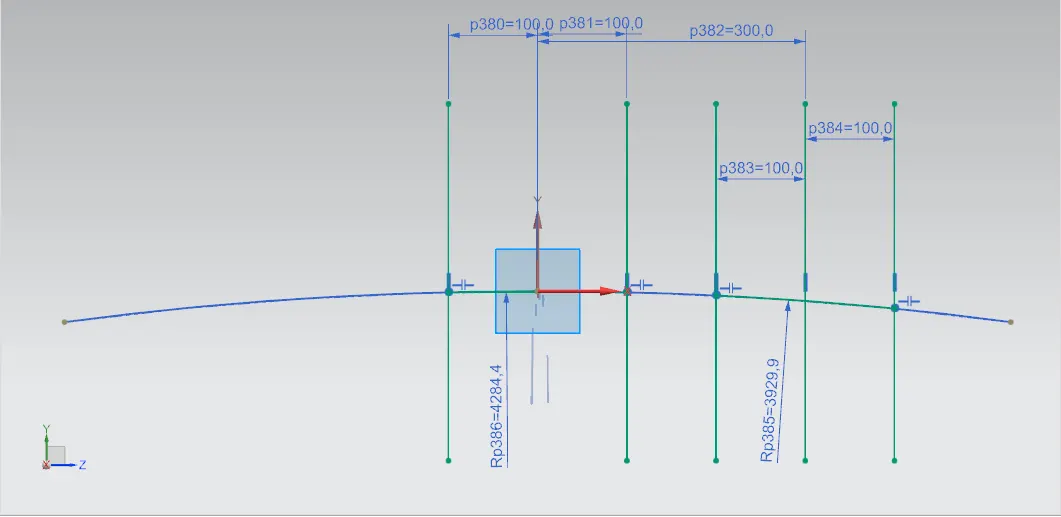
X CROSS SECTION SKETCH - FONT VIEW OUTER PANEL- BETWEEN 2ND BOW AND REAR BOW - OUTER PANEL
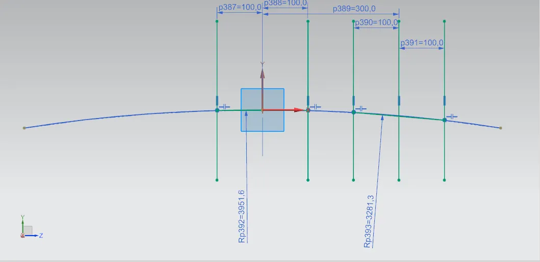
- left side arc - snow load
- right side arec - heat distortion
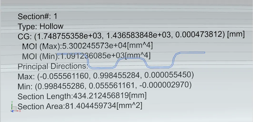
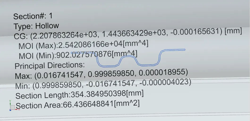
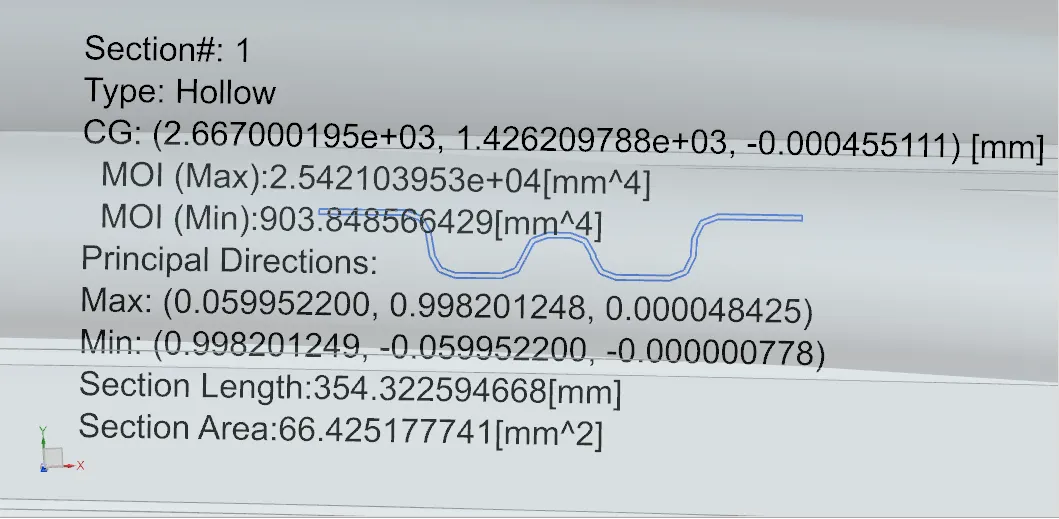
Y CROSS SECTION INTERTIA OF BOWs
CENTER ROOF BOW / B PILLER BOW
1st BOW
2nd BOW
Bow–Roof Prediction Formula
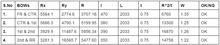
W = [1.73 x 10^(-3) x L] + [1.85 x 10^(-8) x (R^2)/t] + [ 1.10x10^(-3) x l] - 2.68
- L = Roof Length in X-Direction[mm](Roof dimension in 0-Y)
- R = Roof curvature
- R = 2(Rx*Ry)/(Rx+Ry)
- Rx = X curvature
- Ry = Y curvature
- t = Roof plate thickness [mm]
- l = Bow Roof Span [mm]
Judgment Condition
OK< 2>
Snow Load Prediction Formula
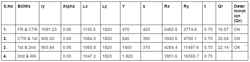
Qr = [Iy x t2] / [α x s x [(Rx + Ry)/2]2 x 10-8]
Note: The Qr value given over here is correct. There was a typo error in the formula given in the video.
Where,
- α = My x Lx2 x 10-12 , My = Y(Ly-Y)
- t = Roof plate thickness [mm]
- Ly = Distance between the front and rear roof Rails on the Vehicle along with 0Y[mm]
- Length of Roof panel with the center point between Roof rail Front /Rear as the front and rear reference point.
- Lx = Distance between the Left and Right end of the roof on the Roof BOW [mm]
- The width of the roof panel is exposed on the surface.
- Y = Distance front Front Roof Rail to Roof BOW[mm]
- s = Distance for which Roof BOW bears divided load [mm]
- s = L1/2 + L2/2
- Iy = Geometrical moment of inertia of Roof BOW (Y cross-section )[mm4]
- Rx = Lateral direction curvature radius of roof panel Y cross-section on Roof BOW [mm]
- Roof panel curvature Radius of the Length Lx in Front view
- Ry = Longitudinal Direction curvature radius of the Roof panel X cross-section on Roof BOW [mm]
- Roof panel X curvature radius of length s in Side view
Judgment condition
Qr ≥ 3.1
250 ≤ s ≤ 380
Therefore,
The Design of Roof and Its Reinforcement is passed the heat distortion and snow load test. now the design is forward to the simulation engineering team for test.
DRAFT ANALYSIS
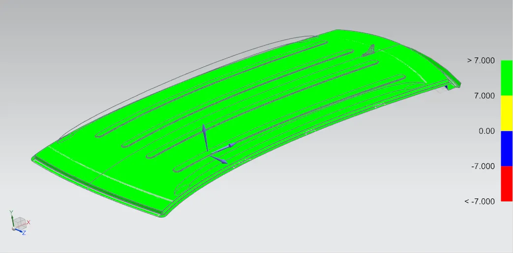
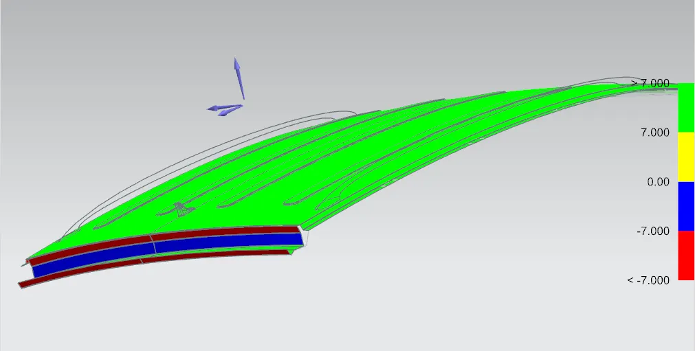
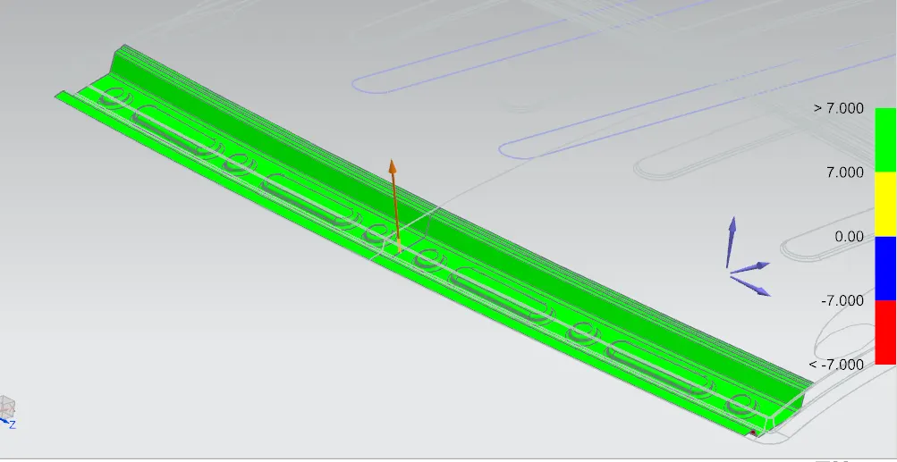
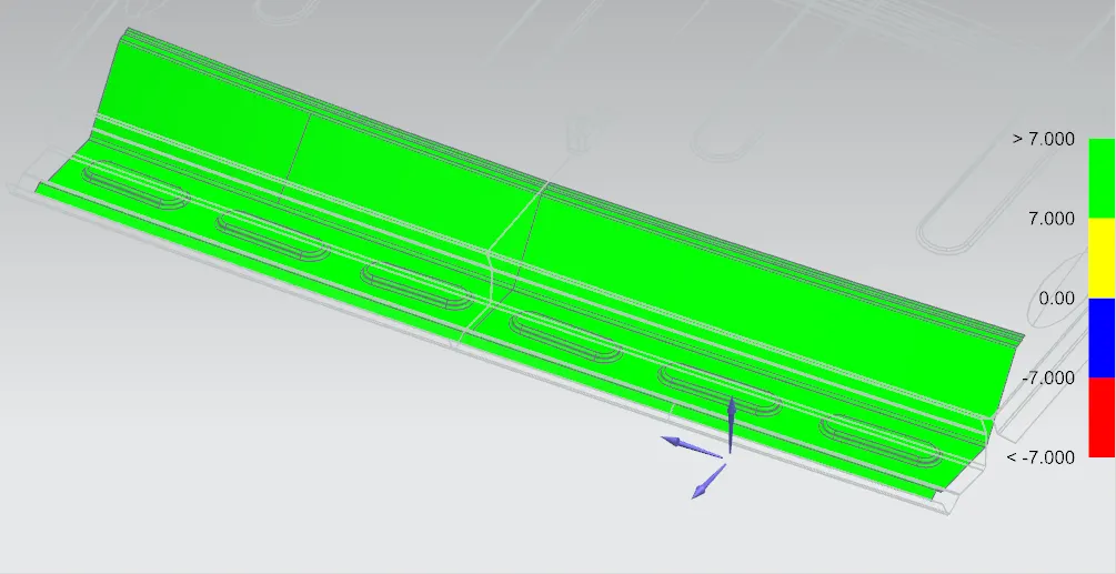
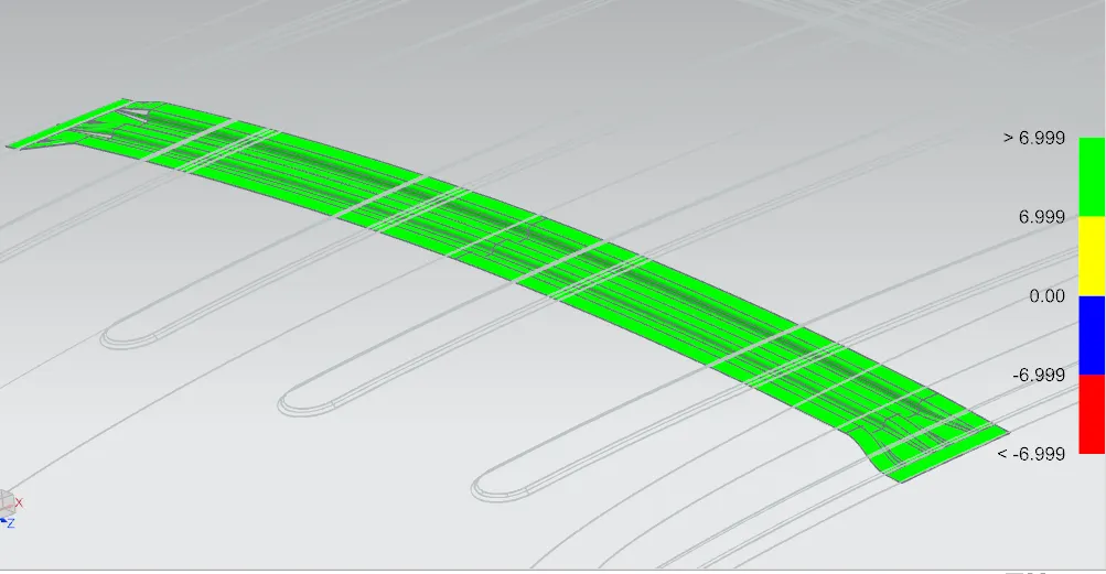
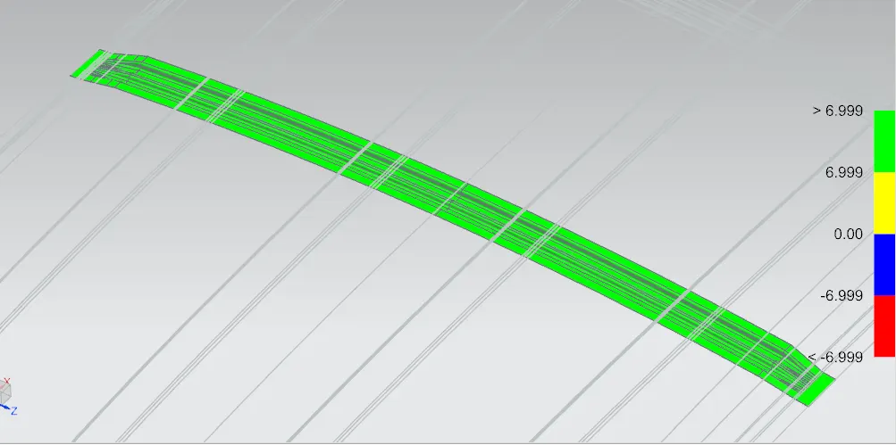
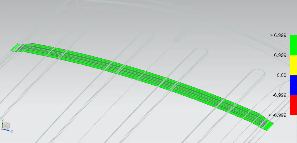
- All parts are designed by given input and master section
- Draft angle - 7 deg
ROOF OUTER PANEL
FRONT BOW
REAR BOW
CENTER BOW/ B PILLER BOW
1st BOW
2nd BOW
MANUFACTURING PROCESS
- Outside plate can be manufactured with the following process, first the open straight snips plate: first select applicable cold coiling specification, cold coiling is opened flat. Then according to production material specification it will be opened after flat and be cut into the iron plate of corresponding size. Finally the iron plate after shear is cleaned into iron filings. Then its trimmed and punched. Then its flanged and punched. Finally, after punching completed it is carried out to the operation of side folding.
- Bar shaped assembly and ring-shaped component are processed by blanking, stamps out iron plate the outline blank of many roof cant rails, a ring-shaped component and a bar shaped assembly.
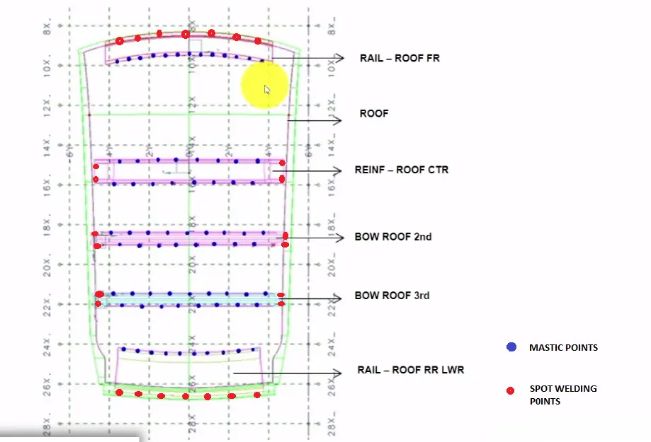
ROOF MASTICS
- Mastic points are given on the various points of the roof to join the inner and outer panel of the roof. It also develops Good NVH for the car. Mastic sealants provides strength locally around 80mm of its point of application. So we need order the points in a way that the it is evenly spread over the roof so that we can increase the strength of the roof. Mastic sealants applied on the roof will undergo hot bath where it expands and fills the 80mm of its surrounding.
SPOT WELD
- Spot welding is a type of electric resistance welding. It is also known as resistance spot welding. The process of spot welding is sheet metals are made into contact with each other and pressure is applied on specified points. So heat is generated from the resistance and weld is formed. Here below you can see the points to be spot welded in the roof panel.
DESIGN AND PRODUCT VALIDATION VIA DIFFERENT TYPES OF TESTS
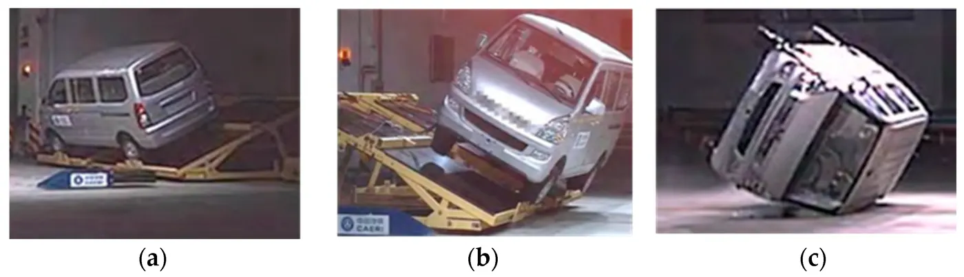
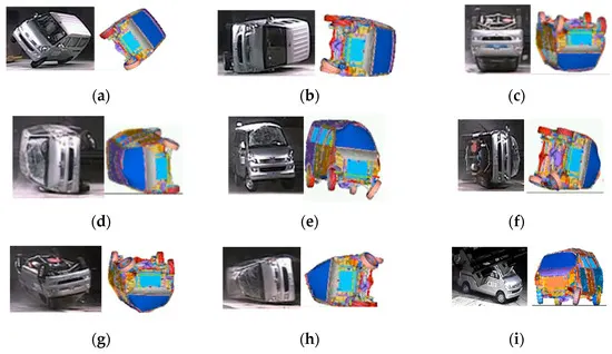
VAN ROLLOVER MODEL - SIMULATION TEST
- The causes and conditions of rollover accidents vary greatly, and due to the high cost and lengthy cycle of platform rollover tests, this study developed a finite element model of a van for simulation analysis.The main objective of the test was to evaluate whether the top structure of the vehicle had sufficient strength to ensure the integrity of the vehicle’s living space after an accident.
ROOF CRUSH TEST
- A rectangular block measuring 30 inches wide and 72 inches long is used to apply the load on car roof with 1.5 times the unloaded vehicle weight with different angle inclination to rectangular block. The moving distance of roof structure must be less than 127mm or 5 inches as per FMVSS standards.
PLATFORM ROLLOVER TEST
- This test was conducted in accordance with the FMVSS 208 [17] regulation, which adopted a driver-side-first landing case. The main objective of the test was to evaluate whether the top structure of the vehicle had sufficient strength to ensure the integrity of the vehicle’s living space after an accident. The test also aimed to reproduce vehicle rollover accidents caused by physical inertia due to sudden braking, emergency lane change, or impact with a curb during driving.