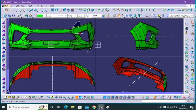
Week 8 - Challenge 4 - Bumper
THE CREATION AND DRAFT ANALYSIS OF BUMPER
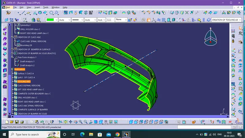
TOOLING AXIS:
- The direction of open and close operations in Molding Machines, basically the Direction of the Mold pulls apart.
- The Mold is built in two seperate pieces. so, you have a Cavity and Core sides.The Core pulls apart from the Cavity is the Tooling direction.
THE CREATION OF TOOLING AXIS:
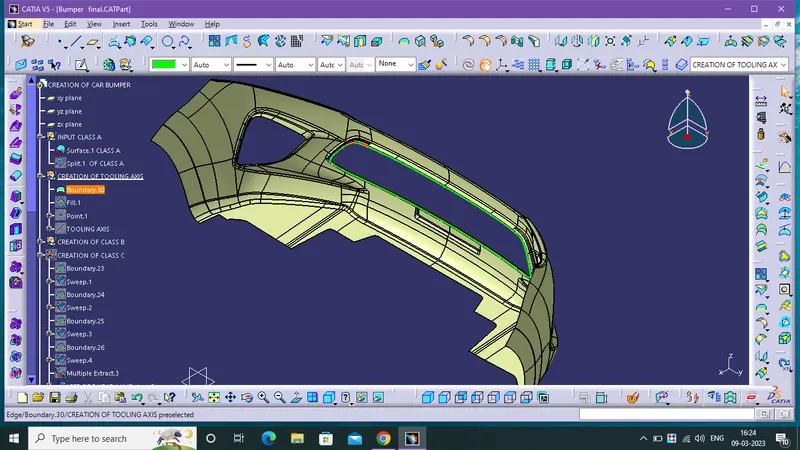
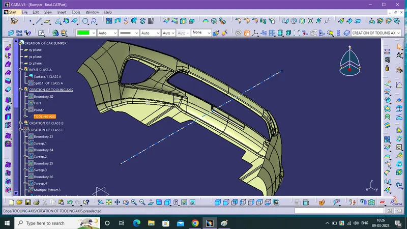
- First Find out the possible directionn of Drafting, in this component it have a four walls and four side edges in Grill Holder so, The axis is created from this references.
- Create a boundry of that Grill Holder.
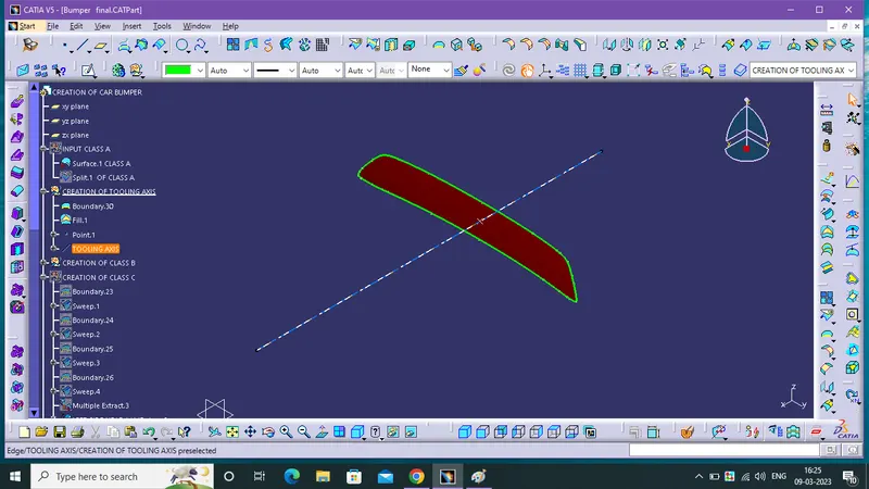
- Fill the Boundry and create a point in the middle of the filled surface .
- Finally create A line with the help of point.
THE DRAFT ANALYSIS TECHNIQUE:
- The draft analysis technique is used to analyse whether our part model created in CAD is manufacturable based on the draft condition applied. Here the part should get easily removed from the panel dies (in case of Sheet metal part) or Mold (in case of plastic).
- No parts can be ejected from the tool if it is having a straight 90-degree profile from its base surface. A small draft angle is provided to each and every area of the component in order to get easy removal of the component from the tool.
- Here we are providing a direction in which components should eject in order to get easy removal of components from the tool. In other words, it also lets us know whether the model is having a draft angle and how much is the draft angle from the tool direction.
DRAFT ANALYSIS OF PLASTIC COMPONENTS:
- The ideal draft angle for the plastic components is 3 degrees. This may vary according to the functional requirement. Apart from the draft angle consideration, the remaining procedures for the draft analysis are similar to the above-mentioned steps. The draft angle provided for the plastic features is 0.5 degrees. This may also get varied accordingly.
THE DRAFT ANALYSIS OF THE CLASS-A SURFACE:
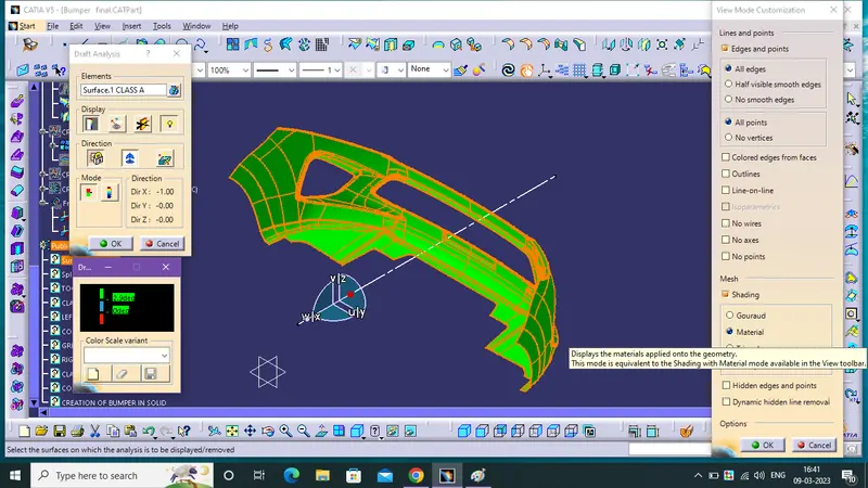
- First Enable The Class A Surface for Draft Analysis. then, select the Material Mode on View Mode Customization.
- Insert a Draft Analysis then, click a Compass and drag into the main tooling axis then fix it in the axis with using lock.
- enable the draft angle colour code dialog box for class A surface
THE DRAFT ANALYSIS OF THE FINAL PLASTIC COMPONENT:
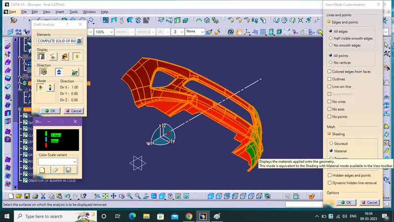
- First Enable The Final Solid Bumper for Draft Analysis. then, select the Material Mode on View Mode Customization.
- Insert a Draft Analysis then, click a Compass and drag into the main tooling axis then fix it in the axis using lock.
- enable the draft angle colour code dialog box for Bumper.
THE SOLID MODEL WITH THE PROPER COLOR CODE DRAFT ANGLE IN VARIOUS ORIENTAION (FRONT, TOP, SIDE AND ISOMETRIC VIEWS):