Week 12- Final project
FINAL PROJECT - PANEL ASSY. - REAR DOOR TRIM (RH) WITH ENGG. FEATURES DEVOLOPED FROM GIVEN CLASS(A) & MASTER SECTIONS
GIVEN DATA:
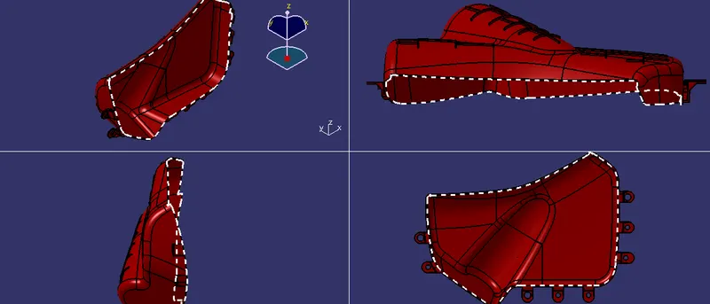
- CLASS A surface of door trim lower substrate, arm rest, map pocket and bottle holder.
- Creation of engg. Features and class A & B Distance took from given Master Sections.
- Push pin catpart for assembly with door trim.
TOOLING AXIS:
- The direction of open and close operations in Molding Machines, basically the Direction of the Mould pulls apart.
- The Mould is built in two separate pieces. so, you have a Cavity and Core sides.The Core pulls apart from the Cavity is the Tooling direction.
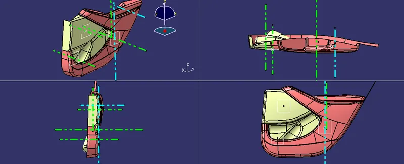
THE CREATION OF TOOLING AXIS:
- First Find out the possible direction of Drafting.
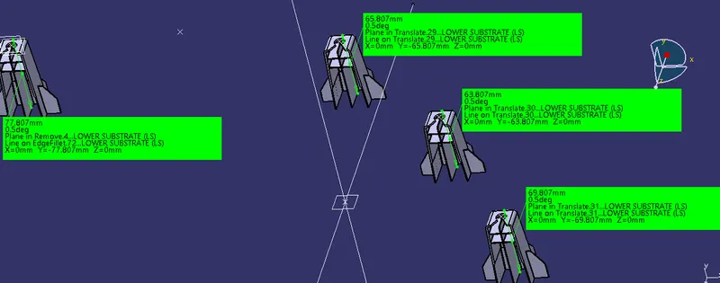
- Create the Main Tooling Axes Lines from the class A surfaces.
- Create a Side core Axis Line based on the requirement. Ensure that, The axes are clearing the Draft Analysis.
THE DRAFT ANALYSIS TECHNIQUE:
- The draft analysis technique is used to analyse whether our part model created in CAD is manufacturable based on the draft condition applied. Here the part should get easily removed from the panel dies (in case of Sheet metal part) or Mould (in case of plastic).
- No parts can be ejected from the tool if it is having a straight 90-degree profile from its base surface. A small draft angle is provided to each and every area of the component in order to get easy removal of the component from the tool.
- Here we are providing a direction in which components should eject in order to get easy removal of components from the tool. In other words, it also lets us know whether the model is having a draft angle and how much is the draft angle from the tool direction.
THE DRAFT ANALYSIS OF THE CLASS-A SURFACE:
- First Enable The Class A Surface for Draft Analysis. then, select the Material Mode on View Mode Customization.
- Insert a Draft Analysis then, click a Compass and drag into the main tooling axis then fix it in the axis using lock.
- enable the draft angle colour code dialog box for class A surface.
LOWER SUBSTRATE CLASS A
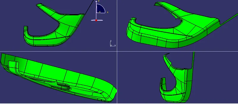
(draft angle 2.9deg - main tooling Axis - lower substrate)
ARM REST CLASS A
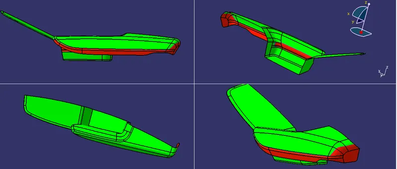
(draft angle 2.9 - main tooling axis - arem rest)
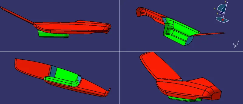
(draft angle 2.9deg - side core axis - arm rest)
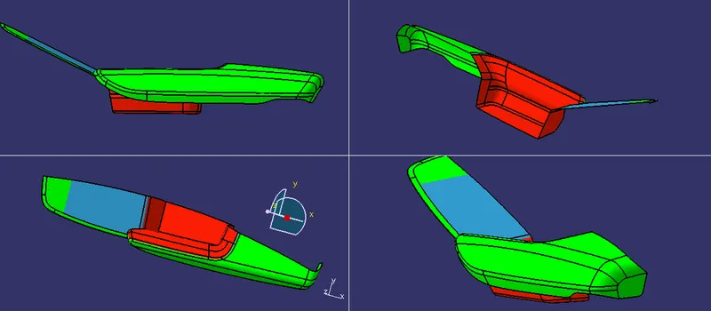
(draft angle 2.9deg - side core axis - arm rest)
MAP POCKET CLASS A
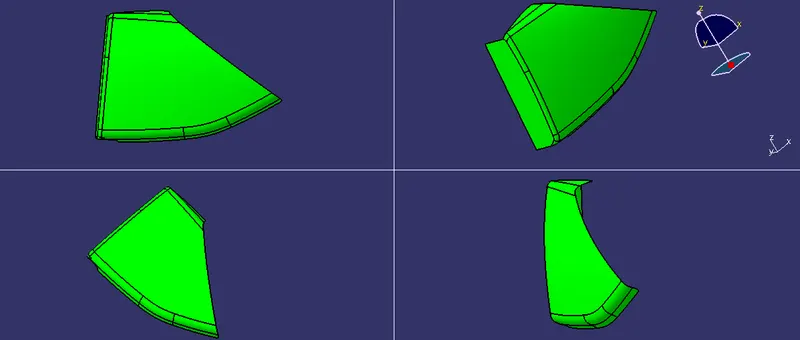
(draft angle 2.9 - main tooling axis - map pocket)
BOTTLE HOLDER CLASS A
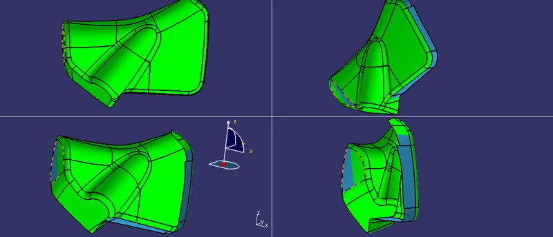
(draft angle 2.9 - main tooling axis - bottle holder - 1.4deg for left side highlighted blue part - another all blue parts are need a rework, from the class A Designer)
DOOR TRIM PANELS:
- All panels are thickened from close surface command from class A,C and B surface Trim.
- wall thickness is 2.5mm for all panels, reference from master section.
DESIGN RULES OF (B-SIDE/ATTACHMENT) ENGG. FEATURES:
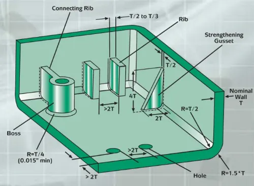
GENERAL GUIDELINES FOR BOSSES AND HEAT STAKES
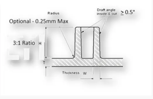
- Draft 0.5 degrees on walls of boss
- Thickness Typically 40% of nominal wall at base.
- Height to Diameter Ratio - 3:1
- Radii-0.25mm maximum radii.
- Boss gussets must meet rib guidelines
- Need to plan ahead for type of ejection.
- If less than 25mm tall, draft is not required when sleeve ejection is used
- Over 25 mm tall, draft is required on outside wall only if sleeve ejection is used
- If sleeve ejection not used, draft is required on all walls
DESIGN RULES FOR RIBS AND GUSSETS
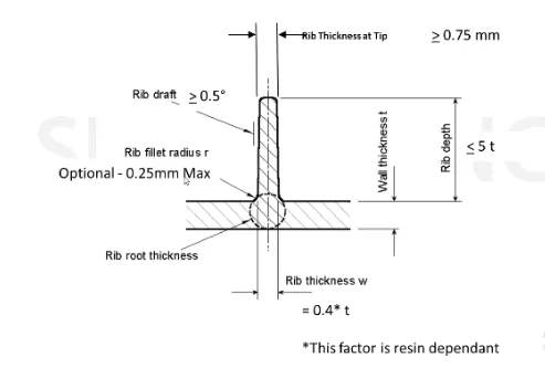
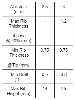
- Draft -0.5 degrees per side minimum
- Thickness - Typically 40% wall thickness
- Height <5x wall thickness
- Spacing 3:1-steel height / width ratio maximum
- Minimum thickness at Tip - .75mm
- Fillet Radii - 0.25mm maximum
- Ribs on opposite side of wall should be offset
- Ribs should be connected to other structural features where possible.
DESIGN RULES FOR DOG HOUSE
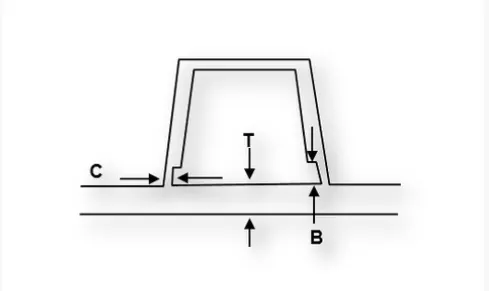
- Draft angle for all faces 0.5 deg, outer fillet 1.5, inner fillet 0.5.
- Core height between 3-6 and thickness 40% of component thickness from Design rules.
CREATION OF DOOR TRIM WITH ENGG. FEATURES:
HEAT STAKES
- Heat stakes are developed from the given master section.
- left side heat stake is connect with arm rest flanges.
- right side heat stakeis connect with map pocket and bottle holder flanges
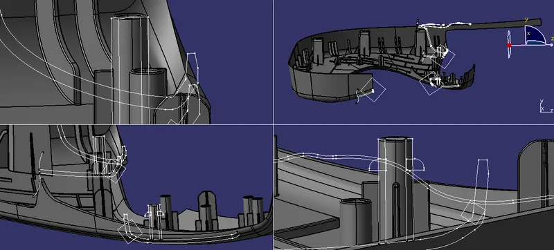
FLANGES
- heat stakes and locators are base referance for the flange creation and counter part clearance.
- Every flanges are had a perfect fixation with heat stakes and lie on heat stake ribs.
- distance between heat stake and counter part clearance (hole) is 0.5 mm.
- distance between four way locator and hole is 0.1mm.
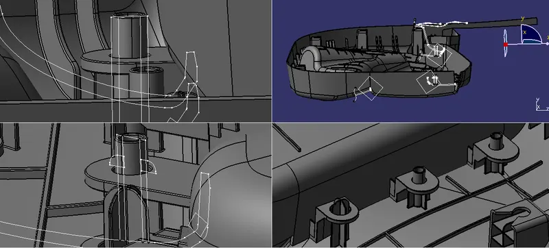
FOUR WAY LOCATOR AND DOG HOUSE
- Four way locator is created after creationn heat stakes in this case we create a locator from the heat stake reference, locator is 5mm higher than heat stake.
- Locator is made a first contact with the flange at the time of assembly for perfect fixation.
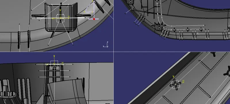
- Dog house is created from the refernce from the push pin. 25x25 block with various heights.
- Dog house is made out for perfect match with push pin and also every dog house is different hight for its reach on the lower substrate but, top of the dog house is same height from the lower substrate class C surface for perfect assembly with push pins for assemblinng with care sheet metal door panel.
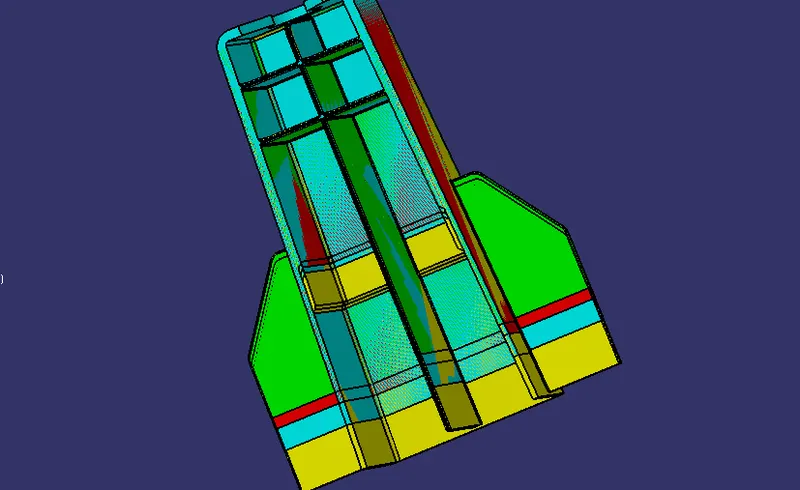
- I created The Key Hole in dog house for push pin assembly.
RIBS, GUSSETS FOR FLANGES AND HONEY COMB DESIGN SPEAKER GRILL
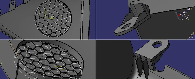
- In the flange creatrion there is a need of ribs and gusset for stength of the flange.
- so, i create a ribs and gussets variously and suitable for every flanges from design guidlines.
- Additionay i created the honey comb design speaker grill holder.
BOUNDARY WALL RIBS AND PANEL RIBS
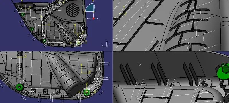
- Boundary walls created for lower substrate panel and panel ribs for lower substrate, bottle holdert panels for extra strength.
DRAFT ANALYSIS OF DOOR TRIM PANELS WITH ENGG.FEATURES:
LOWER SUBSTRATE WITH ENGG. FEATURES
- Lower substrate consist of,
- CLASS A (aesthetic surface of the component).
- CLASS C (thickness of the component).
- CLASS B (back side surface of component).
- HEAT STAKES WITH RIBS.
- FOUR WAY LOCATORS.
- DOG HOUSE WITH INNER AND OUTER RIBS.
- BOUNDAARY WALL RIBS.
- PANEL RIBS.
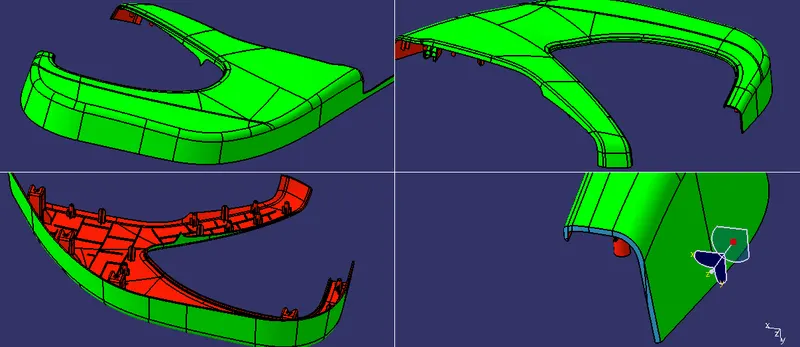
*(draft angle 2.9 - main tooling axis - lower substrate - highilghted blue colour part is clearing the draft in 0.4 deg)
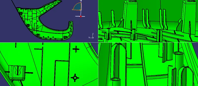
*(draft angle 0.48 - main tooling axis - heat stakes, locators, dog house outer shell, boundary wall ribs and panel ribs)
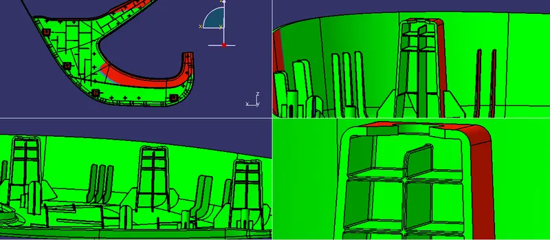
*(draft angle 0.48 - side core axis - dog house inner shell and ribs)
ARM REST WITH ENGG. FEATURES
- CLASS A
- CLASS C
- CLASS B
- FLANGES WITH COUNTER PART CLEARANCE (HOLES)
- GUSSETS AND RIBS FOR FLANGES
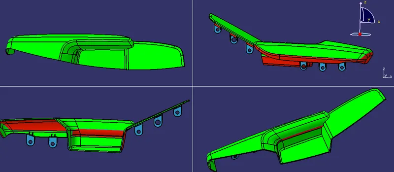
*(draft angle 2.9 - main tooling axis - arm rest)
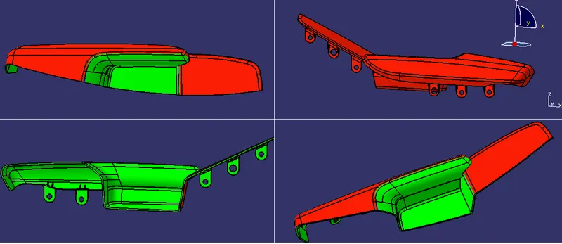
*(draft angle 2.9 - side core axis - arm rest)
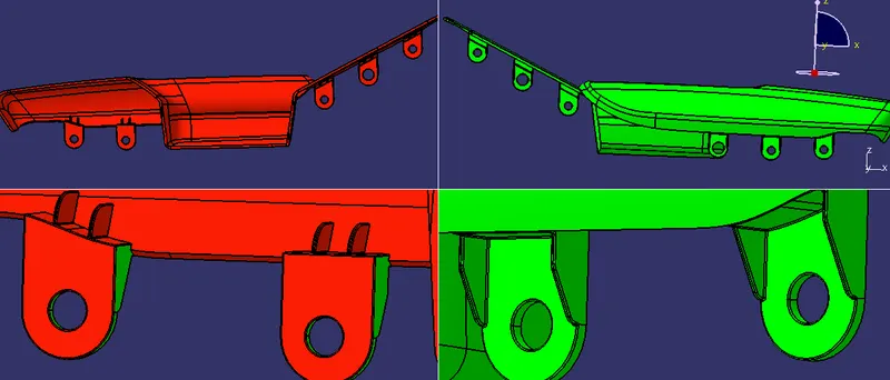
*(draft angle 0.48 - side core axis - flanges, holes and gussets)
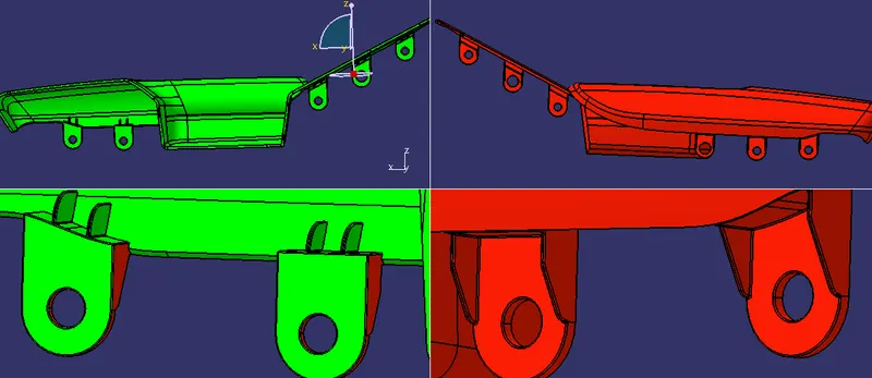
*(draft angle 0.48 - side core axis - flanges and ribs)
MAP POCKET WITH ENGG. FEATURES
- CLASS A
- CLASS C
- CLASS B
- FLANGES WITH COUNTER PART CLEARANCE (HOLES)
- GUSSETS AND RIBS FOR FLANGES
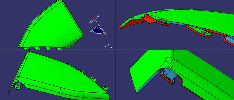
*(draft angle 2.9 - main tooling axis - map pocket - 0.45deg blue colour part of class C surface)
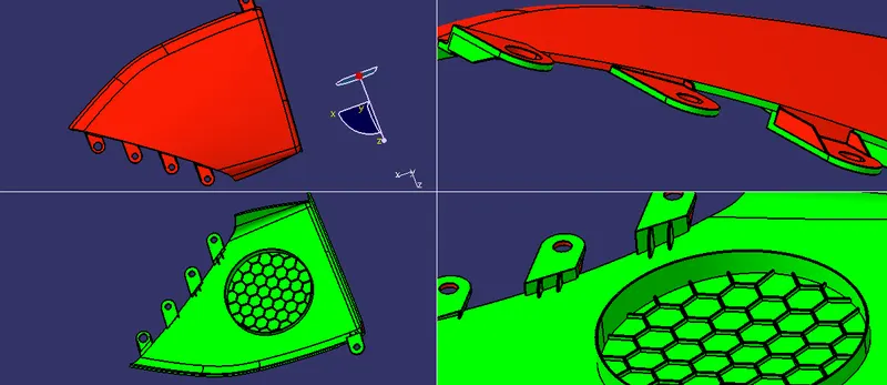
*(draft angle 0.48 - main tooling axis - flanges, ribs and speaker grill ribs)
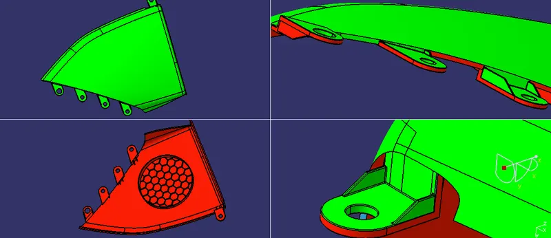
*(draft angle 0.48 - main tooling axis - flanges and gussets)
BOTTLE HOLDER
- CLASS A
- CLASS C
- CLASS B
- FLANGES WITH COUNTER PART CLEARANCE (HOLES)
- GUSSETS AND RIBS FOR FLANGES
- PANEL RIBS
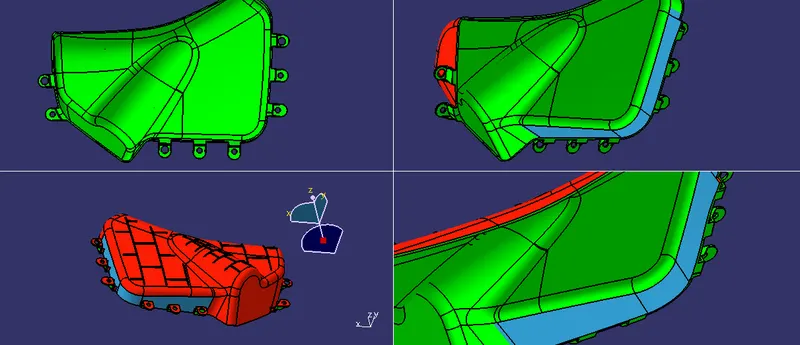
*(draft angle 2.9 - main tooling axis - bottle holder - blue parts are need a rework, from the class A designer)
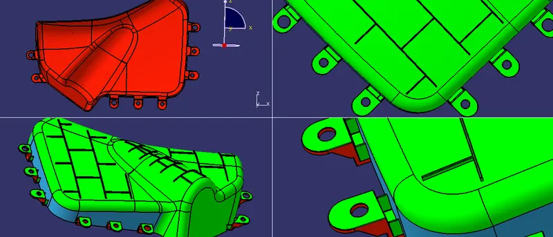
*(draft angle 0.48 - main tooling axis - flanges, ribs and panel ribs)
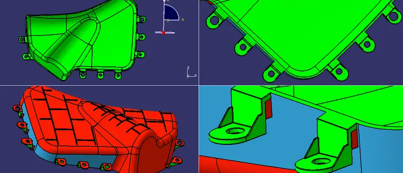
*(draft angle 0.48 - main tooling axis - flanges,holes and gussets)
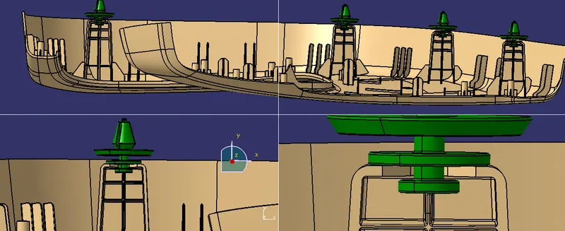
ASSMBLY LOWER SUBSTRATE DOG HOUSES WITH PUSH PINS:
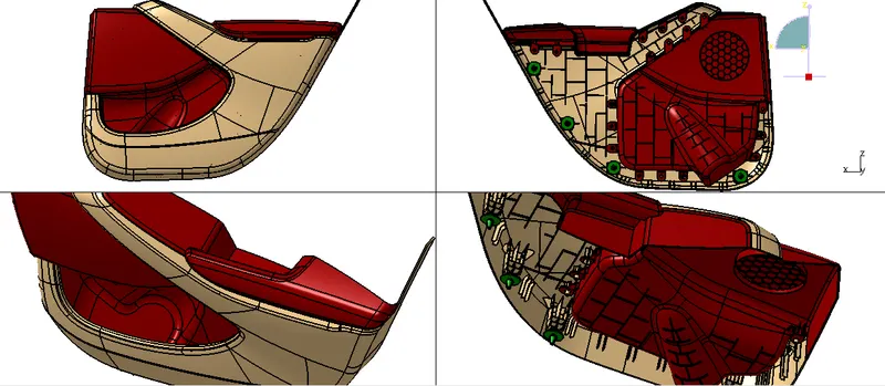
- In the door panel assembly the lower substrate is made a contact with the push pins.
- push pins are assemble with the dog houses perfectly, which are located in the lower substrate.
COMPLEATE DOOR PANEL ASSEMBLY WITH ENGG. FEATURES:
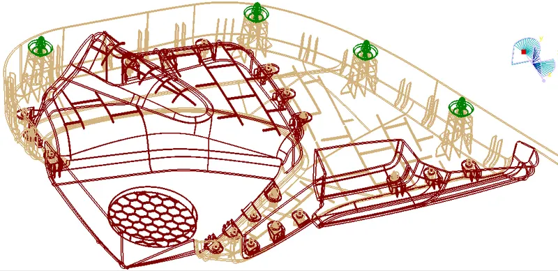
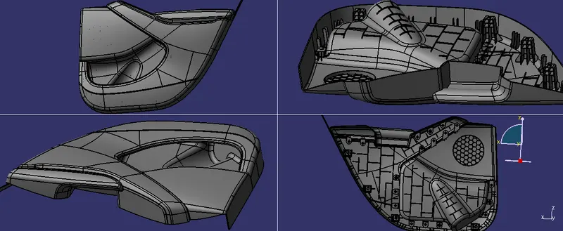
- The Door Trim panel assembly consist of Lower substrate, arm rest, map pocket, bottle holder
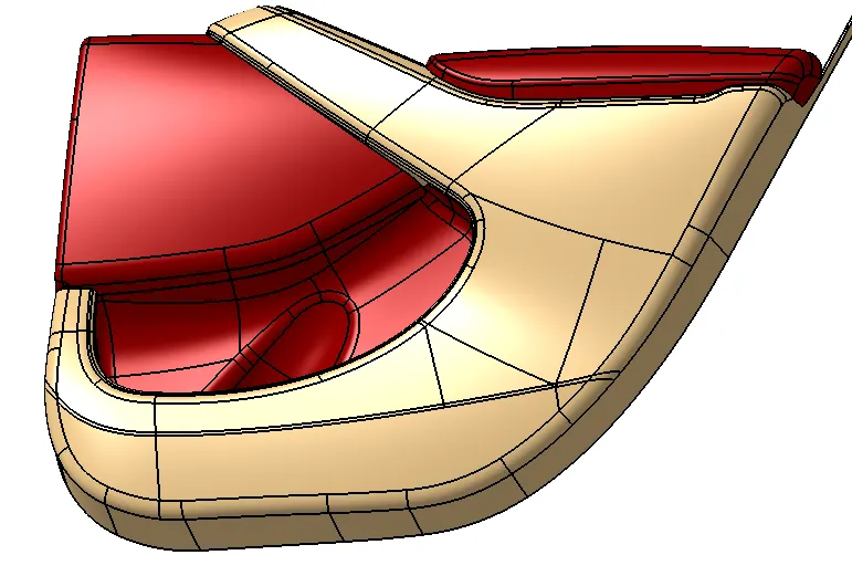
- Assembly of Door Trim with Push pins

APPLY MATERIAL IN DOOR TRIM PANEL:
I Applied the PLASTIC MATERIAL for every panel and measured the mass. the values are,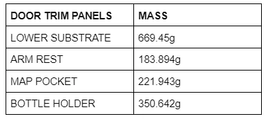
PARTING LINE:
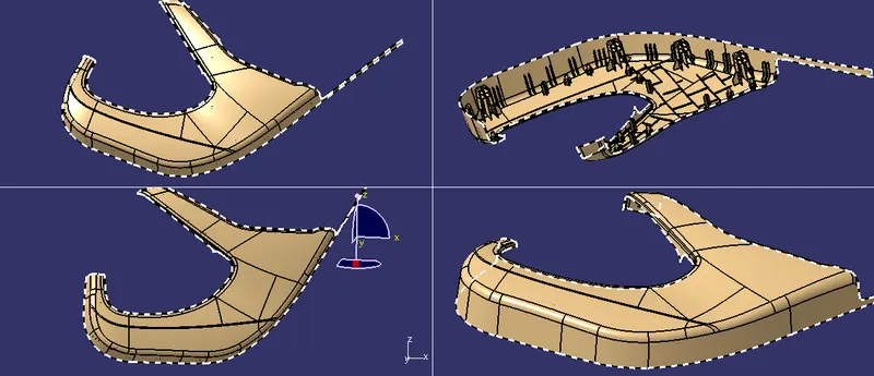
- A parting line, in industrial casting of moulds, is the border line in which draft angles change direction. One can check the parting line in the mould or product which divides the two half, i.e; the core and the cavity of a molded part. It is sometimes a starting point for the mold parting surface.
LOWER SUBSTRATE PARTING LINE
ARM REST PARTING LINE
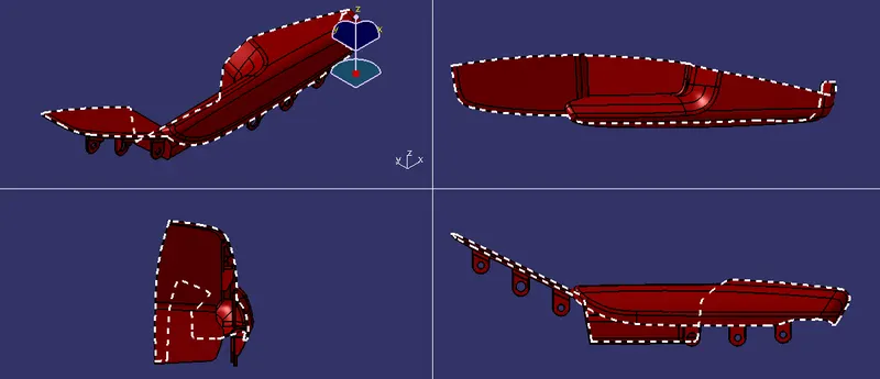
MAP POCKET PARTING LINE
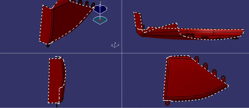
BOTTLE HOlDER PARTING LINE