Wiring harness design in CATIA V5 - 3D modeling Week 5 & 6 Challenge
WIRING HARNESS DESIGN IN CATIA V5 - 3D MODELING WEEK 5 & 6 CHALLENGE
Routing the following harness layout in Electrical workbench. Using the connectors provided.
IN THIS CHALLENGE AND REPORT:
- ELECTRICAL DEFINITIONN AND CATALOGUE CREATION.
- BUNDLE CONTINUITY AND ANNOTATION CREATION.
- THE INTERCONNECTION FOR HARNESS A AND B.
- BUNDLE WARNING AND GENERATION OF CATpart AND CONVERSION TO Iges FILE.
ELECTRICAL DEFINITIONN AND CATALOGUE CREATION:
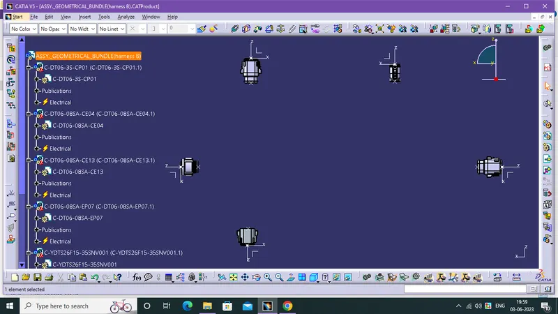
- All connectors are defined as electrical parts before adding in the product file using Electrical part workbench.
- the geometrical supports like points and axis systems are created in the mechanical part workbench.
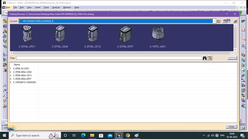
- Electrically defined connectors are saved in the Specific Catalogue for assembly and reusage.
BUNDLE CONTINUITY AND ANNOTATION CREATION:
- Create a Product file then, add the Connectors in to the product from the Catalogue, based on requirement.
- Connectors are positioned at the exact location in Mechanical Assembly using the move toolbar commands like manipulation,tranformation,rotation and compass.
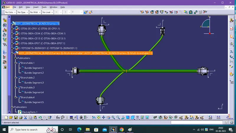
- Define the Product into Electrical Product, using the Geometrical Bundle command in Electrical Harness Assembly workbench.
- now, use Multi Branchable Document command in product and create a main Branch using Branch Definition and split the branch for sub branch using Add Branch Point then use Branch Definition for Sub Branch creation.
- check the boundle continuity using search
- Edit-->Search-->Advanced-->Electrical -->Bundle Segment-->Fully Connected--> chosse TRUE or FALSE then click a search.
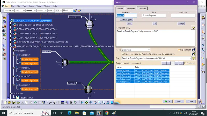
- This is harness B, all bundle are successfully connected.
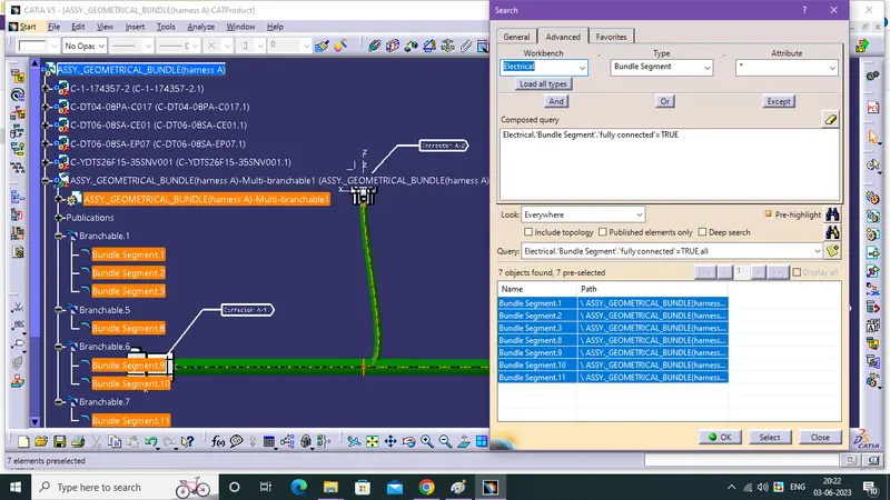
- This is harness A, all bundle are successfully connected.
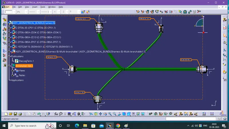
- using the annotation toolbar for annotation
- Annotaion Tool Bar-->View from reference-->Front view-->Flag note with reader then select a connector and its face for plane then type the name and fix the annotation.
THE INTERCONNECTION FOR HARNESS A AND B:
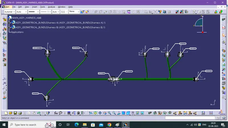
- We use the move toolbar commands like manipulation, rotation, transformation, and compass for the Interconnection of two connectors from two different products in assembly.
- In this condition we don't use the Coincident command for interconnection for harness A and B bcoz, it is not recommended to use the coincident command from the external product and interconnect the connectors from two different products.
BUNDLE WARNING AND GENERATION OF CATpart AND CONVERSION TO Iges FILE:
- All bundle warnings are cleared by modifiying the slack, bundle radius, connnector location and reverse tangent in routing.
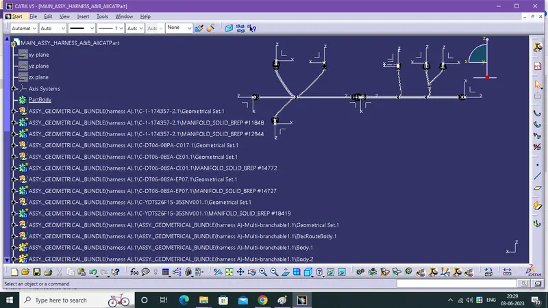
- Tools --> Generate CATPart from Product --> select the product, now you got a part file.
- If you need any graphical changes then do it and save it as CATPart.
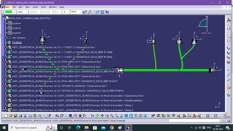
- Fnally select a CATPart and save as igs file format.