Wiring harness design in CATIA V5 - 3D modeling Week 2 Challenge
WIRING HARNESS DESIGN IN CATIAV5 - 3D MODELIMG WEEK 2 CHALLENGE
IN THIS REPOT:
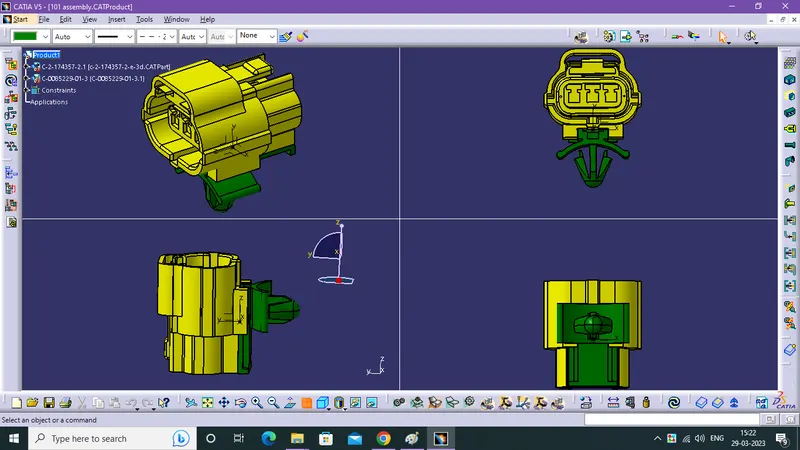
- Downloading the following connectors & Connector clip cad data from given link.
- How to Define it as Electrical Connector using Electrical Part design Workbench. Define all the necessary properties to Connectors & Clip.
- How to save a defined Electrical cad part in catalogue.
- Additionally Basic working of Harness assembly.
Downloading the following connectors & Connector clip cad data from given link:
- This website has a components of Electrical Distribution system.
- Using keyword or link we reach a component dash board and the dashboard contains lots of informations about the product & Cad Data, also have a another product data of using with this component like clips, female connector, male connector etc.,
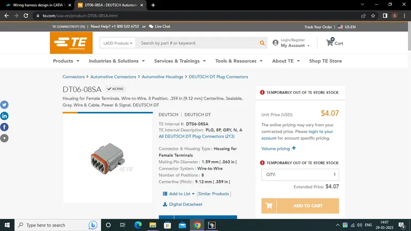
How to Define it as Electrical Connector using Electrical Part design Workbench From Part Workbench. Define all the necessary properties to Connectors & Clip:
*create a point in middle of the face and curve.
*create a axis system similarly as a parent mating product.
Deutsh DT06-08SA:
PART WORKBENCH
- Start from part workbench find out the connector mating face and bundle/wire entry face and clip mounting face (optional).
- Then create a point in the middle of bundle face and mating face. in this case connectoer mating face need a axis system for mating with another component.
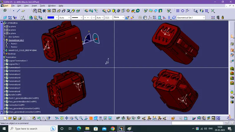
ELECTRICAL PART WORKBENCH:
- After the part workbench, we need to go to the Electrical Workbench for converting the product from mechanical part into electrical part.
- click a connector defintion icon then it shows dialog box. enter the asking data. once enter the data product is defined as electrical part.
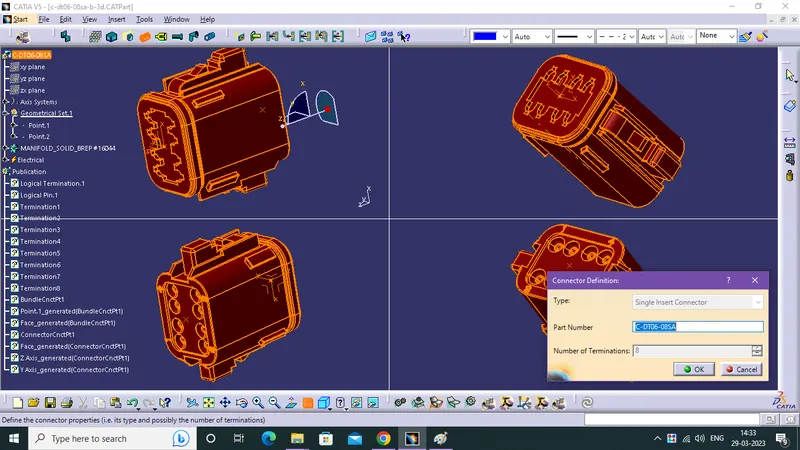
BUNDLE CONNECTION POINT DEFITION
- Now we need to defin the bundle so, click a bundle connection point definition icon and enter the data in the dialog box as given image (reference).
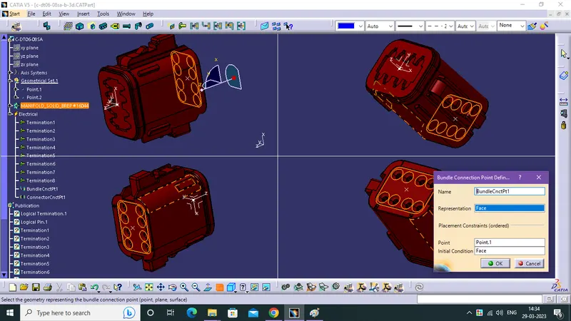
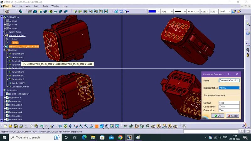
CONNECTOR CONNECTION POINT DEFINTION
- Then click a connector connection point defintion icon and enter the asking data same as given image.
Tyco 174357-2:
- Part workbench ---> Electrical part workbench ---> connector defintion ---> bundle connetion point defintion ---> connector connection point defintion.( same as before )
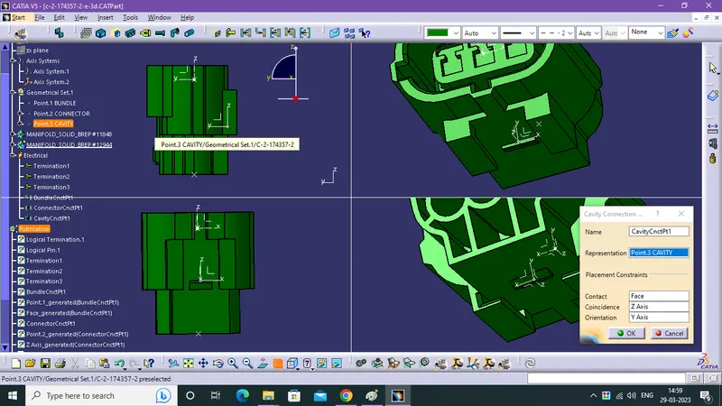
- But in this product it had a cavity connection (clip mounting face) addtionally.
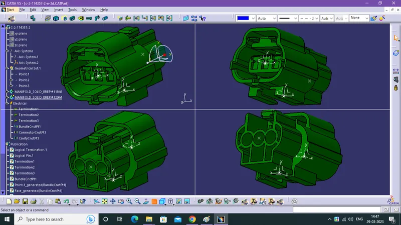
- So, we need to create a point and axis system on cavity connection in PART WORKBENCH, with bundle point and connector point & axis.
- Axis system is needed for mating with the clip.
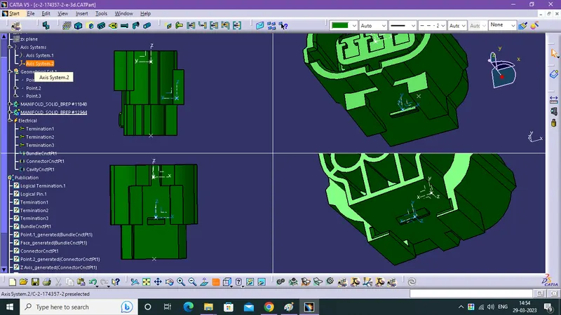
CAVITY CONNECTION POINT DEFINTION
- Finally click a cavity connnection point defintion icon and enter the needed data same a given image.
Dyco 0085229-1
- Part workbench (Create a point & axis system) ---> Electrical Part workbench
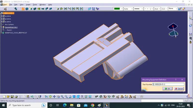
MOUNTING EQUIPMENT DEFINTION
- Click a Mounting Equipment Definition icon and enter the data same a given image.
- Now the clip is conveted from mechanical part into electrical part.
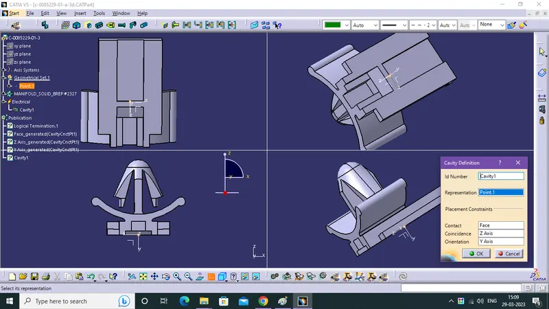
CAVITY DEFINTION
- Click a Cavity Ddefintion and enter the askinng data in dialog box same as given image.
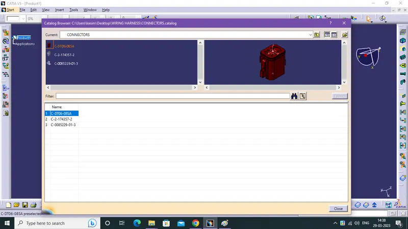
How to save a defined Electrical cad part in catalogue:
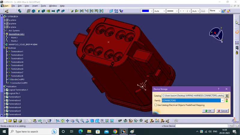
STORE DEVICE
- After the done the INFRASTRUCTURE SETTINGS modifcation for catalog and create a catalog with the help of store device.
- click a Store Device icon after done a work in given catpart and save.
CATALOG
- Catalog reduce the time consuming in designing.
- It is maintaing data of work done catpart, if its here there is no need to start a design from scratch.
- Infrastructure setting is one time effort from design engineer it gives more benefits.
Additionally Basic working of Harness assembly:
HARNESS ASSEMBLY DESIGN WB
- Additionally i make a trial in harnesss assembly design for connector and clip.