Project 1
[PROJECT - 01] ELECTRICAL WIRING HARNESS DESIGN FOR BUGATTI V16 - ENGINE USING CATIA V5:
IN THIS REPORT:
- DEFINITION OF ENGINE WIRING HARNESS
- GIVEN DATA
- ELECTRICAL DEFINTION AND CATALOGUE CREATION
- ASSEMBLY OF ALL COMPONENTS AT EXACT LOCATION
- PROPER ROUTING OF BUNDLES VIA SUPPORT PARTS FOR BUGATTI V-16 ENGINE
- CREATION OF FLATTENING FOR BUGATTI V-16 ENGINE HARNESS
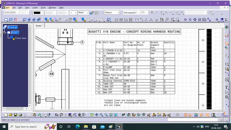
- CREATION OF DRAWING FOR BUGATTI V-16 ENGINE HARNESS
DEFINITION OF ENGINE WIRING HARNESS:
- Automobiles, airplanes, and machinery manufacturers will install dozens, hundreds, or even thousands of wires running connecting one component to another. If all these wires remained loose, it would not only increases the risk of electrical problems but also impedes the ability to perform routine repair and maintenance. Don’t worry. engine wiring harness is here to help.
- An engine wiring harness is constricted wires, cables, terminals, and connectors controlling a vehicle’s electrical system. It relays electrical power and control information to components such as batteries, alternators, fuel injectors, fuses, audio systems, blower motors. Wire harness companies customize it for every location, application, and design it interconnects.
- Manages the key functions around the engine including engine controller, oil controller gate, transmission plug housing, air pipe sensors, pressure sensors, and water temperature sensors.
- Also known as a cable harness , it is more than just a collection of multiple wires put together.
- The harness also reduces the likelihood of electrical problems that would otherwise affect the vehicle or equipment. Flame retardant overmolding minimizes the risk of electrical fires. Also, It shields cables and wires from moisture, thus preventing corrosion. In addition, by installing the harness on the vehicle or machinery’s frame or chassis, there is a lower likelihood of damage from abrasions and vibration.
GIVEN DATA:
- Engine cad data to be downloaded from www.grabcad.com and Engine file, or Engine file Lite version - for systems having low RAM CAD Files
- Available connector and clips,clamps 3D data can be used, or download the connectors from Hellermann Tayton.com and www.te.com
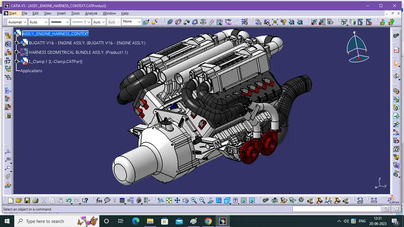
* Follow and acheive the Tree structure same as in the image, harness geometrical bundle assly is most important bcoz it consist all of the electrically defined components, suports, guiding channel and bundle segments, cot tube.
ELECTRICAL DEFINTION AND CATALOGUE CREATION:
Step - 1:
- Create a points and a axis system based on that requirement and rules in Part Design WB.
- Go to Electrical Part Design WB and define the products, now mechanical part convert into electrical part.
- use define connector and connector connection pt., bundle connection pt.
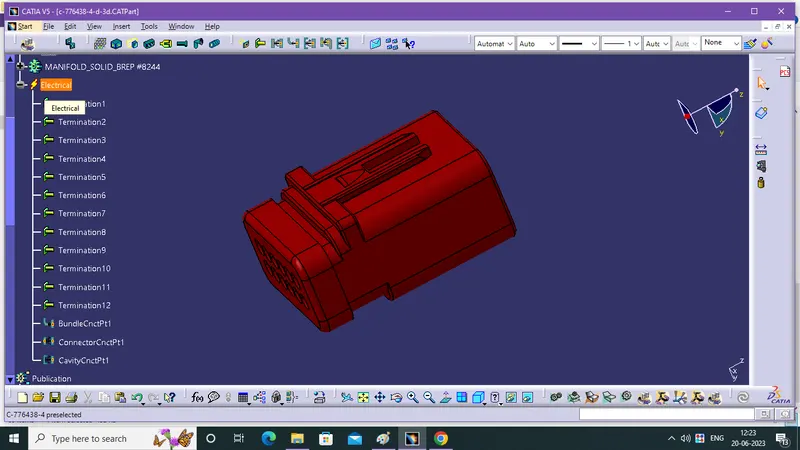
- save the components in the specific catalogue.
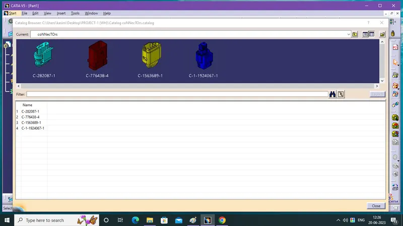
Step - 2:
- Create a points and a axis system based on that requirement and rules in Part Design WB.
- Go to Electrical Part Design WB and define the products, now mechanical part convert into electrical part.
- use define support part twice for dual entry and exit of bundle.
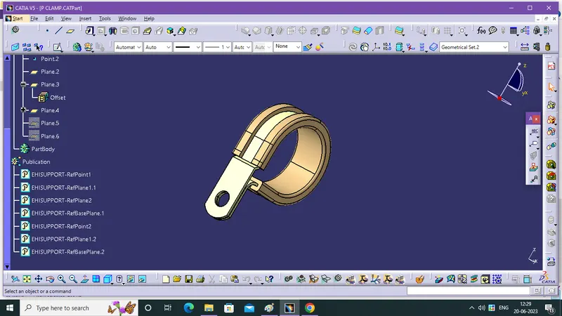
- save the components in the specific catalogue.
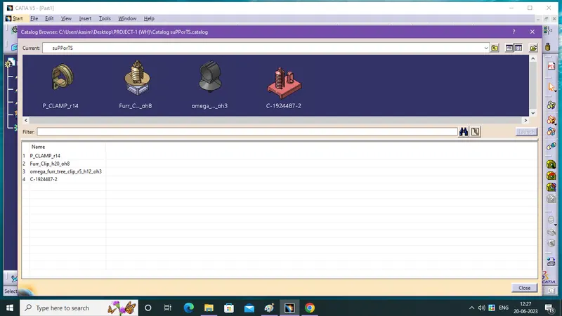
Step - 3:
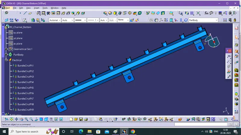
- Create a points and a axis system based on that requirement and rules in Part Design WB.
- Go to Electrical Part Design WB and define the products, now mechanical part convert into electrical part.
- use define equipment and bundle connection pt,. in 9 places for bundle routing.
- create line for routing via channel.
ASSEMBLY OF ALL COMPONENTS AT EXACT LOCATION:
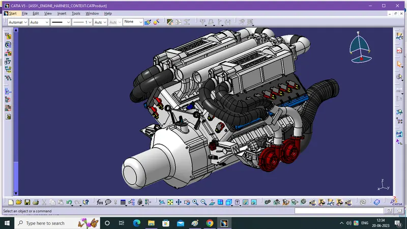
- Using mechanical assembly work bench, move toolbar commands and compass for fixation of components at exact location.
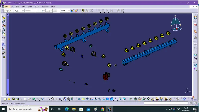
PROPER ROUTING OF BUNDLES VIA SUPPORT PARTS FOR BUGATTI V-16 ENGINE :
Step - 1:
- Define the Harness Geometrical Bundle Assy.Product into Electrical Product, using the Geometrical Bundle command in Electrical Harness Assembly workbench.
- now, use Electrical Harness Assembly WB, Multi Branchable Document command in product and create a main Branch using Branch Definition
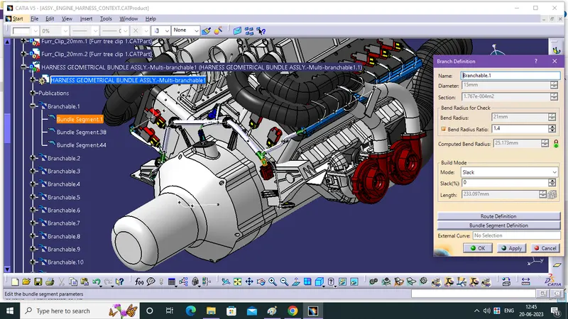
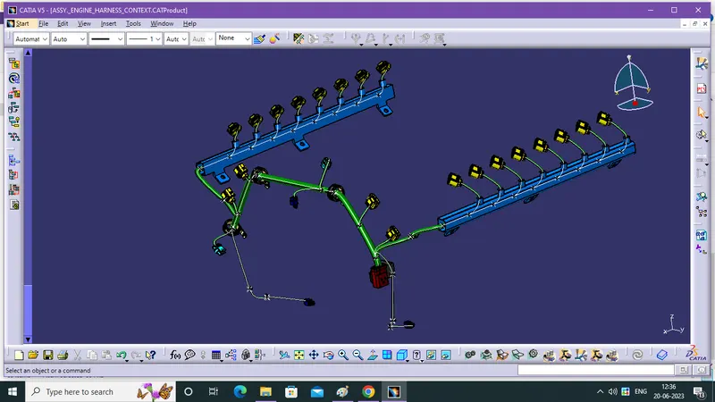
- select the component like following image for first Route Definition then, select the bundle segment and component for all route dedfinition for fully connected bundle segment to achive the Flatten.
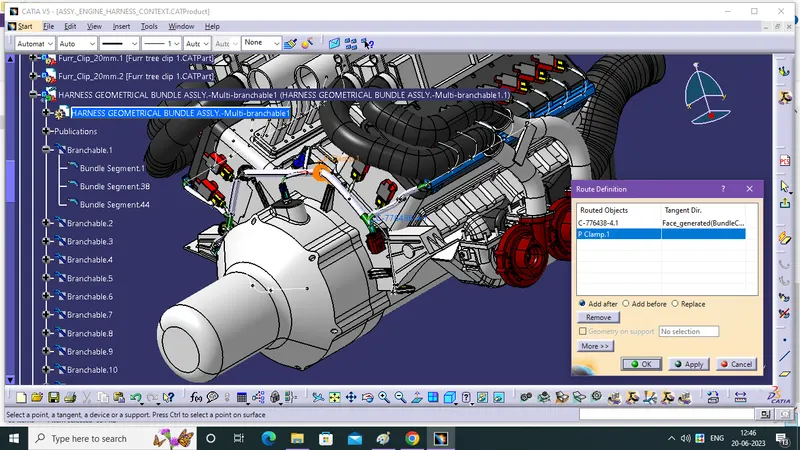
Step - 2:
- split the branch for adding sub branch using Add Branch Point then use Branch Definition for Sub Branch creation in Electrical Harness Installation WB.
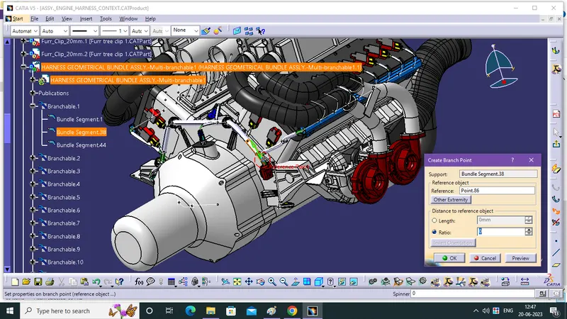
- complete routing of engine.

Step - 3:
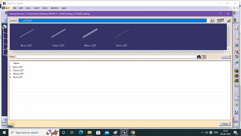
- In Electrical Part Design workbench, Create a corrugated tubes and tapes as required dimensions and save them into specific catalog. tapes are don"t have a specific dimension.
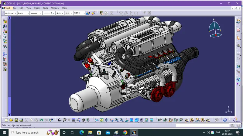
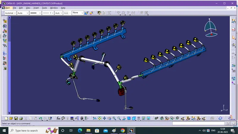
- Electrical Harness Assembly, now add covering, using Protective Covering command in Electrical Harness Assembly WB and select the branches then pick the COT Tubes from catalog.
Step - 4:
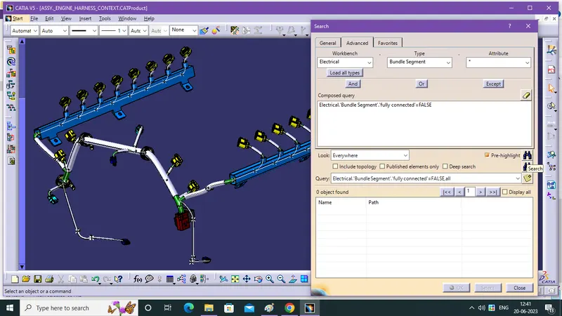
- Bundle segment connectvity is mandatory for Flattening, so check the connectivity using Edit-->Search and follow the below image for reference setting.
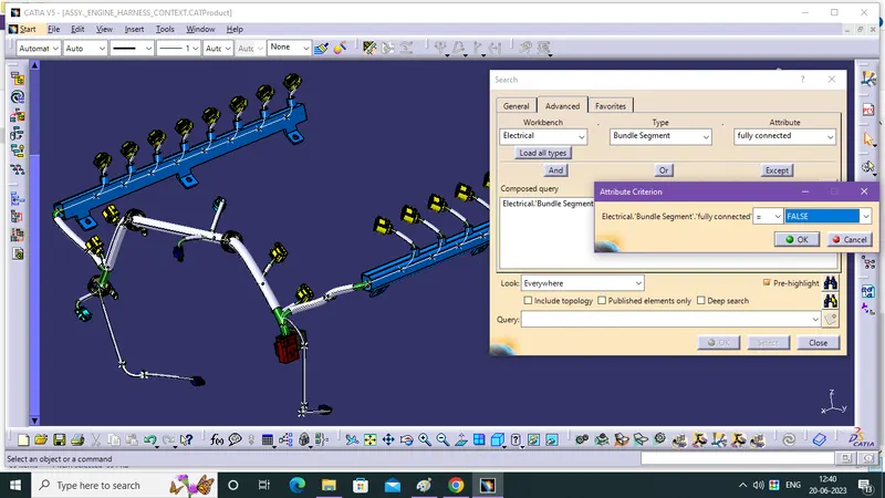
- Now there is No False segment connectivity, segment is fully connected so, it is ready to Flattening.
CREATION OF FLATTENING FOR BUGATTI V-16 ENGINE HARNESS:
Step - 1:
- Create a product file and save it in the same location where the wire harness or routing assembly Product File is stored.
In Electrical Harness Flattening WB:
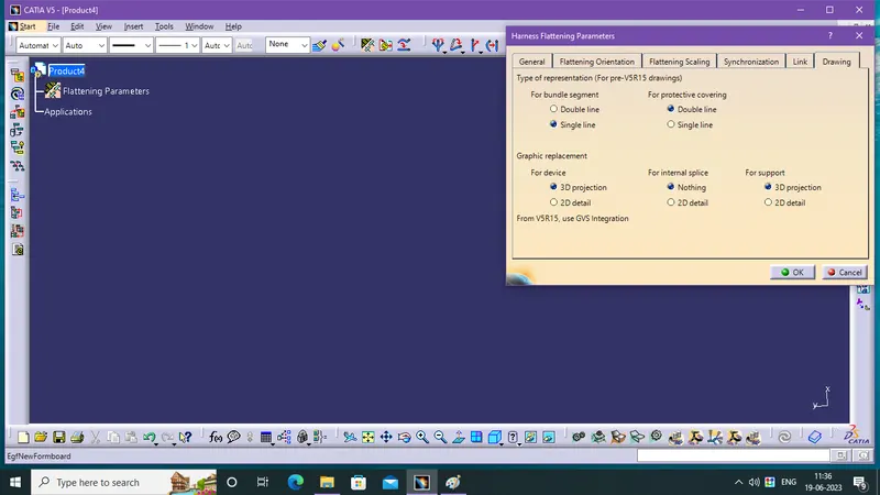
- Open the Electrical Harness Flattening WB then Define the Harness flattening parameters. like shown in following fig.,and rest of the parameters are don't need a edit, so default settings are enough for those.
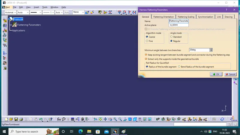
- Active Plane selection, you can select a another plane, face or continue with default xy plane.
Step - 2:
- Select the Extract command for importing the product file into the Flattening WB.
- Then, the geometric bundle assembly product is modified into geometric bundle assembly Ehf product now save it as a Ehf product.
Step - 3:
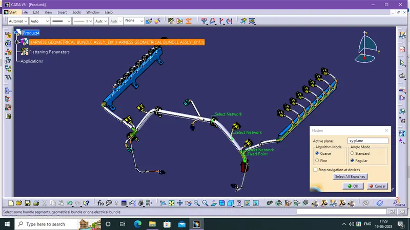
- Select the Flatten option to flatten the wire harness assembly.
- Then select the active plane, then select any one branch or First Branch Bundle segment and then select the 'select all branches'.
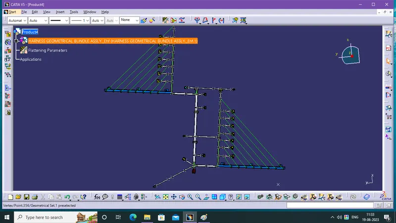
- If there is no discontinuity in the bundle segment then all the branches will be selected and by pressing 'ok' the wire harness assembly will be flattened.
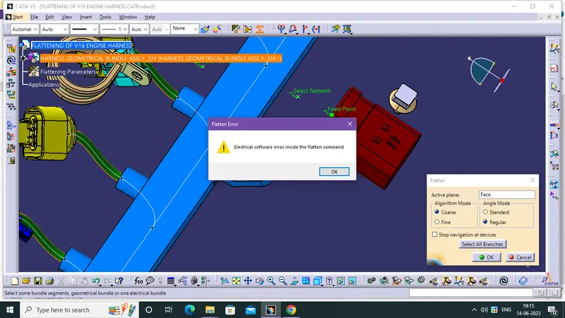
* I got Error while Flatten the Harness like in the following image, then i re-route the bundle and re-define the supports and guiding channel lots of time, i done Flatten in my 15 the attempt.
Step - 4:
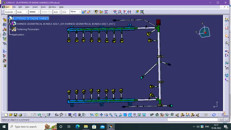
- Use Manipulator Toolbar commands, like Rotate and other commands to move the branches and bring them in proper orientation as per the given layout.
- If any need of modification in bundle segments and cot tubes do it in normal assembly product then save it, and now use the Synchronize command and update the modification in Ehf product.
CREATION OF DRAWING FOR BUGATTI V-16 ENGINE HARNESS:
Creating 2D drawing of the bundle with connector representation and diffrent colour coding for bundle with protective covering:
- Create a new drawing file and save the file in the same location.
In Drafting WB:
- Insert the title block template and fill up the required details.
- Import the 3D assembly into 2D drawing sheet using front view command, Add the front view of the harness assembly by selecting any one of the flat faces of the connector and orient the view as per the requirement.
- Go to the properties of the view and select the '3D Wireframe' on and ' Is always visible' option in order to see properly the Wire bundle, connectors and the protection coverings.
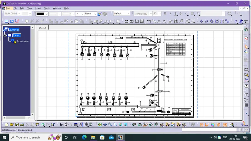
- If need of colours due to differenciation between components then enable the 3D colors.
- now black colour diagram is convet into colour diagram, the colours are cary out from its 3D components colour.
- add a Title Block from Edit.
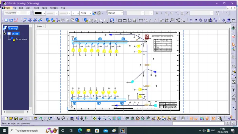
- manually created bill of materaial box.