Fender Design
FRONT FENDER DESIGN (LH)- AUTOMOTIVE SHEET METAL USING SIMENS NX CAD / CATIA V5
IN THIS REPORT
- GIVEN DATA
- THE AUTOMOTIVE FENDER
- TYPES OF MOUNTS IN FENDER
- DESIGN REQUIREMENT FOR THE FENDER AND ITS COMPONENTS
- FENDER DESIGN
- MANUFATURING PROCESS OF FENDER
GIVEN DATA
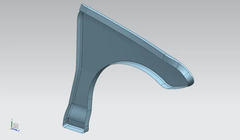
SKIN DATA
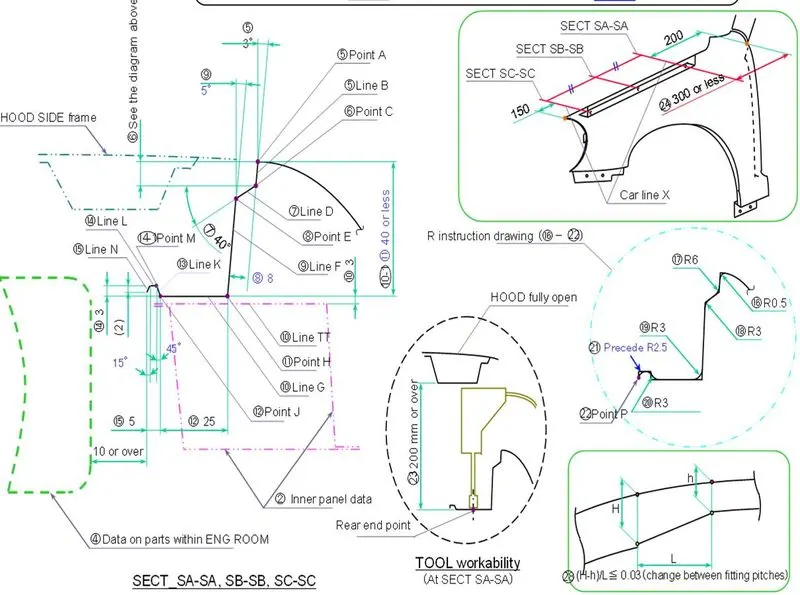
MASTER SECTION DATA OF DRIP MOUNTING
THE AUTOMOTIVE FENDER
- Fender is the part of an automobile (vehicle body) that frames a wheel well (the fender underside).
- Its primary purpose is to prevent sand, mud, rocks, liquids, and other road spray from being thrown into the air by the rotating tire.
- When vehicle is moving, tires pick up stones and others and hurl them in all directions. Fenders are basically present to prevent any injuries to pedestrians and contain the motion of these particles
- Fenders also play a key role in improving the aerodynamics of the car. To put it simply, when the tires are spinning at high speeds, they generate a lot of drag due to the turbulence they create. A fender that houses the wheels helps to reduce that turbulence. This is due to its curved design, which increases the vehicle’s aerodynamic efficiency.
- Most passenger automobiles have four fenders, one over each wheel. For vehicles with a narrow car body that exposes the tire, the fender is an exposed curve over the top of the tire. For wide body vehicles that cover the tire, the fender forms the wheel well surrounding the tire, and is not directly visible from above the car body.
- Wheel wells tend to be much larger than the diameter of the tire, because they do not move with the tire suspension and consequently must be large enough to allow the full range of tire motion on the suspension without touching the interior of the wheel well.
- More elaborate designs include fender kirts for enclosing the outside edge of the wheel well, and stylized pontoon fenders for exposed fenders.
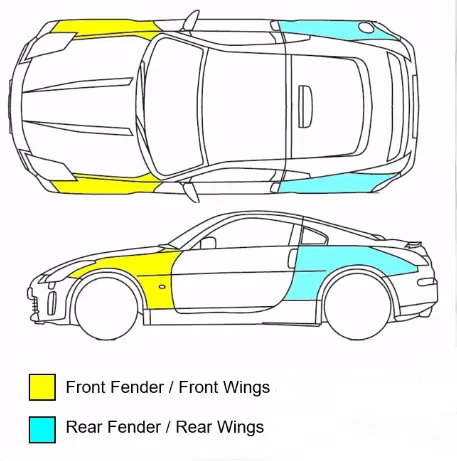
- Fender is the American english word,and also In British english, the fender is called the Wing. (This may refer to either the front or rear fenders. However, in modern Unibody vehicles, rear fenders may also be called Quarter Panels.)
- The equivalent component of a Bicycle or Motorcycle, or the "cycle wing" style of wing fitted to vintage cars, or over tires on lorries which is not integral with the bodywork, is called a Mudguard in Britain, as it guards other road users – and in the case of a bicycle or motorcycle, the rider as well – from mud, and spray, thrown up by the wheels.
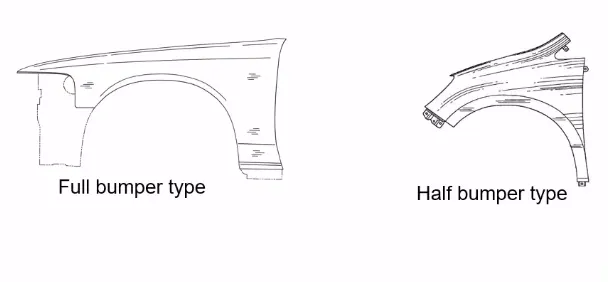
- The Full Bumper type consumes more raw material when compared to the Half Bumper type. Nowadays we don't use full bumper type fenders.
TYPES OF MOUNTS IN FENDER
- DRIP MOUNT
- A-PILLER MOUNT
- SILL MOUNT
- BUMPER MOUNT
- BAFFLE (SPLASH) MOUNT
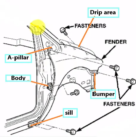
DESIGN REQUIREMENT FOR THE FENDER AND ITS COMPONENTS
- Functional Requirements
- Drip Area
- Wheel Arch
- Baffle and ORVM Mount Area
- FRONTAL CRASH Regulation and Requirement
- GAP and FLUSHNESS Requirements
FUNCTIONAL REQUIRMENTS / DRIP AREA
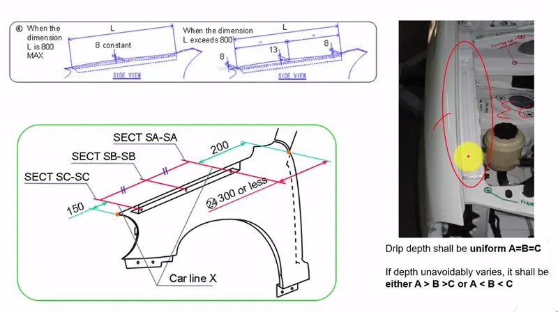
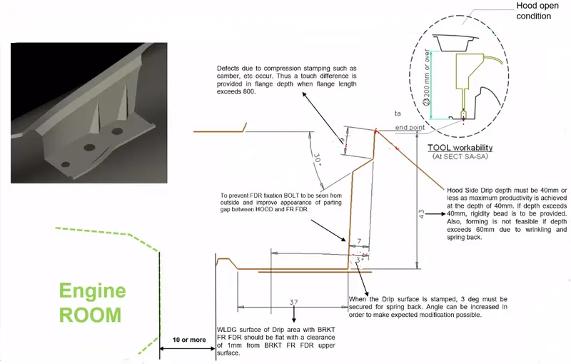
FENDER DRIP AREA PEDESTRIAN SAFTY REGULATION
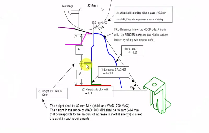
WHEEL ARC CLEARANCE
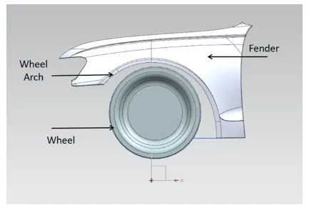
- The fender is an important component on the exterior of the car as it houses the wheel arch which in turn houses the vehicle's wheels. The wheel should ideally sit inside the boundaries of the fender to avoid it from spraying abrasive particles into the air which could potentially cause damage, in the form of chipping to the exterior components of the vehicle or these same particles could be flung onto pedestrians, which again could be dangerous.
- The fender houses a component called a Baffle, which is a plastic component that acts as a shield to the debris that is flung by the wheel of the vehicle.
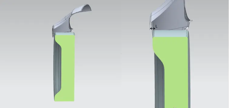
- Horizontal clearance between the Edge of the Fender and Outer most face or Edge of the wheel (Tyre Profile)
Why are there standards between the fender and the wheel?
- The standards state that the wheel of the vehicle should be housed inside the boundaries of the fender so that the purpose of having a fender is met, which is to prevent the wheel from spraying debris and other particles into the engine compartment and onto pedestrians.
- Suppose the wheel is partially/fully placed outside the boundaries of the fender, then the fender cannot prevent or stop particles being thrown up due to the rotation of the wheel and hence all fenders must be designed so that they can house the wheel of the vehicle completely.
What are the different standards?
- There are various standards based on the region the component is being designed for and this is applicable to most components and not just the fender.
- The standards are based on that specific region's environment and conditions which it is being manufactured for.
- For example, there are 3 types of standards mentioned for the fender in the video which are the Japanese, American, and European standards.
JAPAN REGULATION REQUIREMENT
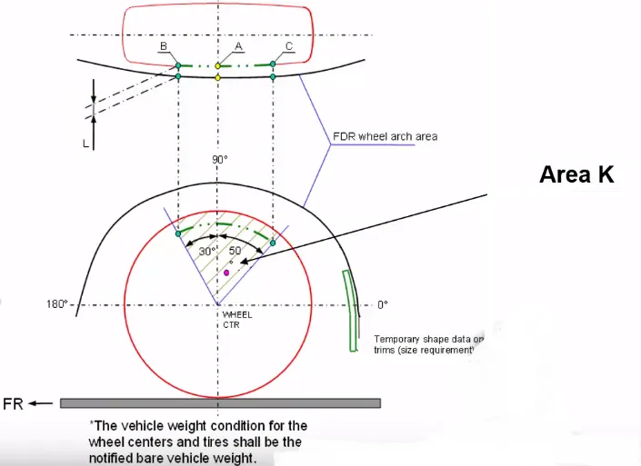
- Measure clearance L of tire,hub, cap & fender in three different positions within area K and produce clearance check chart to validate
- Clearance must be greater than 5 mm in all the three positions.
- Wheel guard reqmt: The value of 'a' shall be more than 5 mm at a line 30* forward and 50* rearward from the central vertical axis of axis of wheel.
EUROPEAN REGULATIONS REQUIREMENT
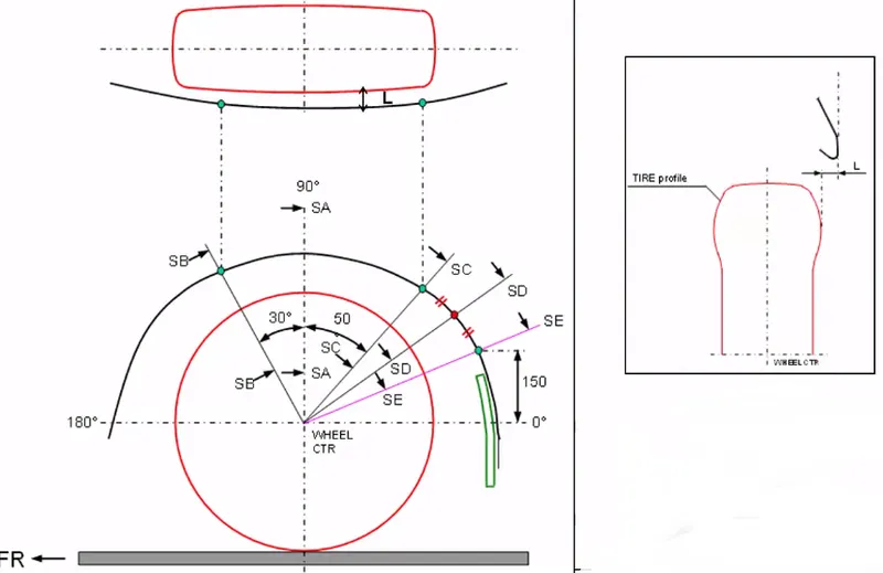
- Measure CL L at sections SA-SA SB-SB SC-SC SD-SD SE-SE and produce CL check chart to validate.
- At all five sections the CL L value should be greater than 10 mm to satisfy the European regulations.
- Wheel guard reqmt: The value of 'a' shall be more than 5 mm at a line 30* forward and 50* rearward from the central vertical axis of axis of wheel.
US REGULATION REQUIREMENTS
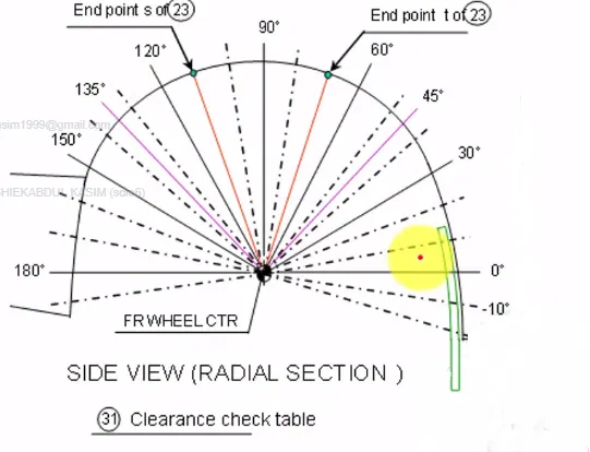
- Make clearance check details on all positions from -100* to 100* & make the clearance check table.
- All values should be greater than 5 mm to satisfy the regulations.
- The value of 'a' shall be more than 5 mm at a line 30* forward and 50* rearward from the central vertical axis of axis of wheel.
- Baffle and ORVM Mount Area
BAFFLE AND ORVM MOUNT AREA
- Baffle is mounted on Car fenders for the purpose of Reducing Noise and Vibration from the Engine compartment to the cabin and pass the NVH Test.
- Noise, vibration, and harshness (NVH) is the study and measurement of aural and tactile feedback in an object. Because sounds can be both an annoyance and a benefit, NVH analysis helps identify where a sound is coming from and why.
- (ORVM) Outside Rear View Mirror mount is normally located on the Front Side Doors, but some case it was mounted on the fenders. Its all about the project.
FRONTAL CRASH REGULATION AND REQUIREMENT
- Frontal crashes are responsible for more deaths and serious injuries than any other accident type. A typical scenario is a head-on collision between two oncoming cars at moderately high speeds. In most collisions of this type, only a part of the vehicle front width structure is involved, i.e. the two colliding vehicles are offset.
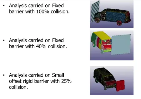
- Optimization for Frontal Impact criteria in which analysis carried on Fixed barrier with 100%, 40% collision and small offset rigid barrier with 25% collision. Done simulation to see how well a passenger vehicle would protect its occupants in the event of a serious real-world frontal crash.
- Design Engineer be responsible for the strengthen the parts and create a design which meets regulation. Importantly selecting material, Force distribution - design of BIW sheet metal parts are must be don't allow the maximum force enter into the cabine so, the impact force is managed, absorbed and distrtibuted to the outer body.
- After the analysis and tests if need of optimaization is there then work on it and optimize the part design which meet regulation.
CRASH ANALYSIS DONE BY SOFTRWARES
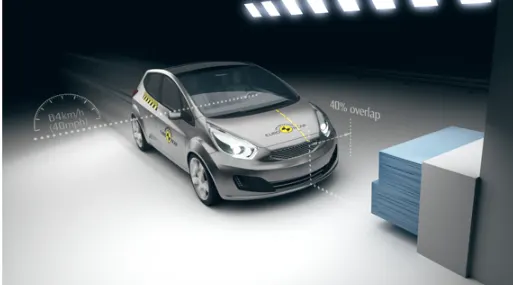
OFFSET DEFORMABLE BARRIER - EURO NCAP
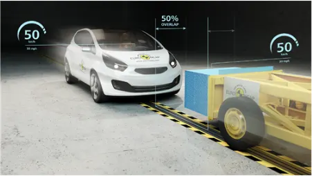
MOBILE PROGRESSIVE DEFORMABLE BARRIER - EURO NCAP
FULL WIDH RIGID BARRIER - EURO NCAP

GAP AND FLUSHNESS
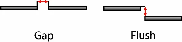
- Gap is defined as the distance perpendicular to the normal surface between two parts, while flush as the distance on the axis of the normal surface between two parts
- As vehicles are assembled, the fit-up of various parts is inspected by measuring the width of the gap between two adjacent panels and the alignment of the two, also called flushness.
- Ensuring good mating and adequate quality control, to keep within tolerances interfaces and related geometrical dimensions, e.g., gap and flushness, is essential for high comfort, noise-vibration-harshness (NVH) performances, low aerodynamic drag and respect some core voice of customer requirements.
DRIP MOUNT DESIGN
FOLLOWING DESIGN REGULATION
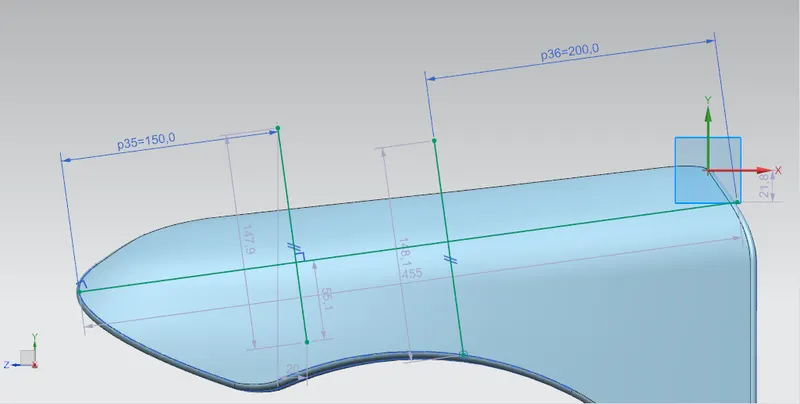
MASTER SECTION SKETCH
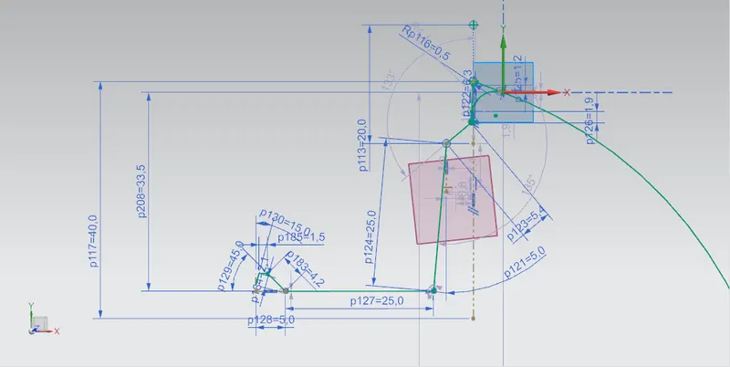
DESIGN IS BASED ON MASTER SECTION
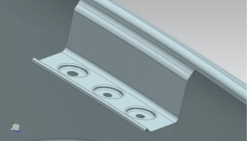
- circular emboss - 16mm dia, depth - 2mm, angle - 7 deg
- blend radius - 1mm
- 3 holes - 5mm dia
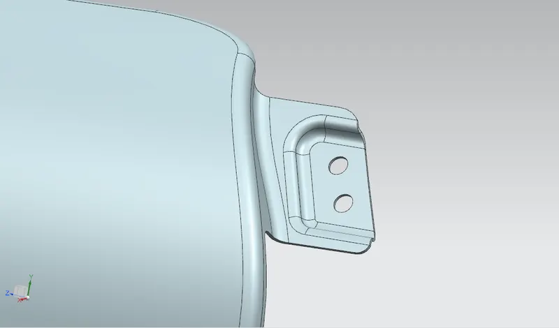
A-PILLER MOUNT DESIGN
- emboss depth - 3.5mm, angle - 12 deg
- blend radius - 3mm
- 2 holes - 5mm dia
- 1 cut out - flange - length 25mm
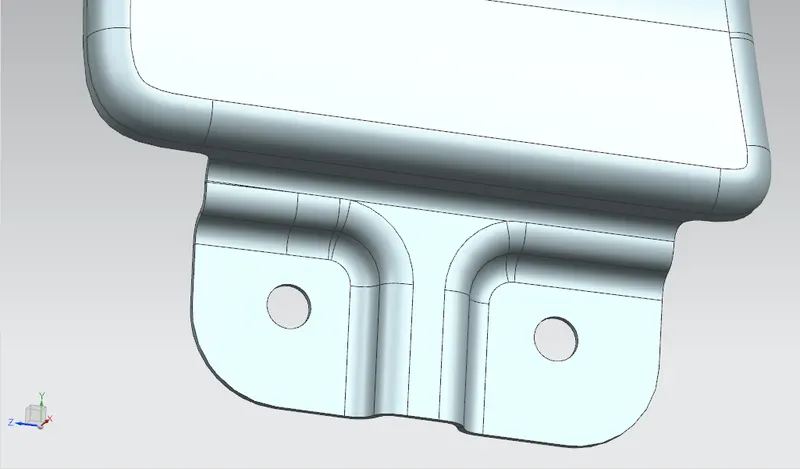
SILL MOUNT DESIGN
- emboss depth - 3.5mm, angle - 12 deg
- blend radius - 3.75mm
- 2 holes - 5mm dia
- 1 cut out - flange - length 25mm
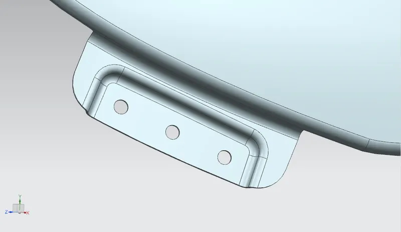
BUMPER MOUNT DESIGN
- emboss depth - 3.5mm, angle - 12 deg
- blend radius - 3.75mm
- 3 holes - 5mm dia
- 1 cut out - flange - length 25mm
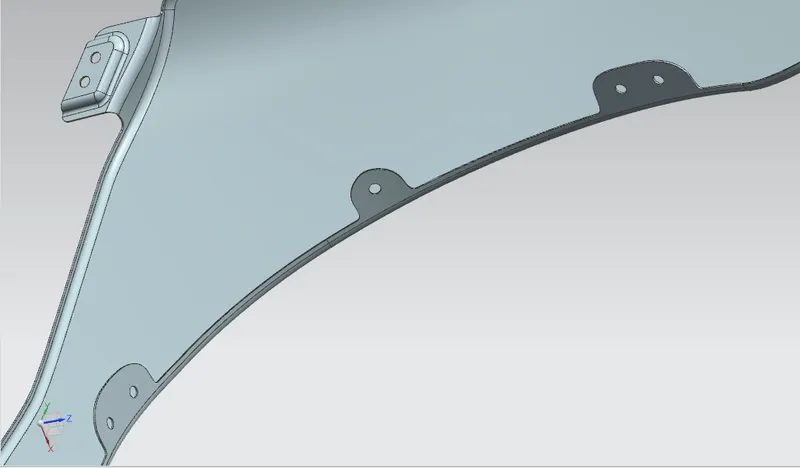
BAFFLE (SPLASH) MOUNT DESIGN
- 3 cut outs - flanges - length 25mm
- 5 holes - 5mm dia
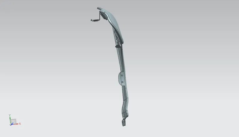
FRONT VIEW
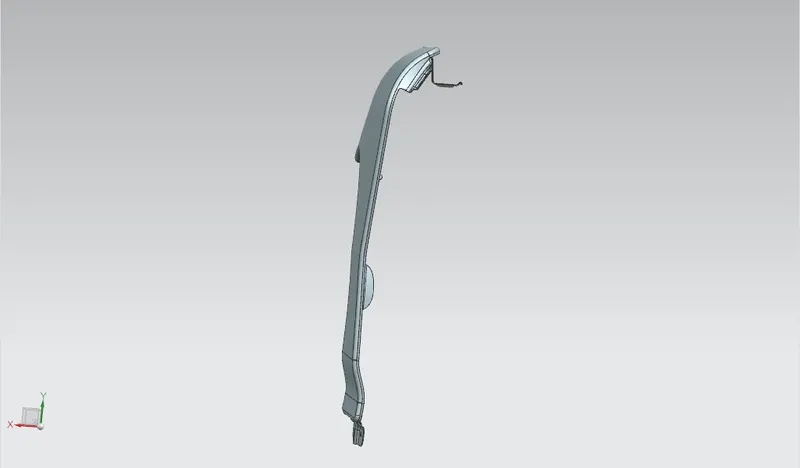
BACK VIEW
SIDE VIEWS
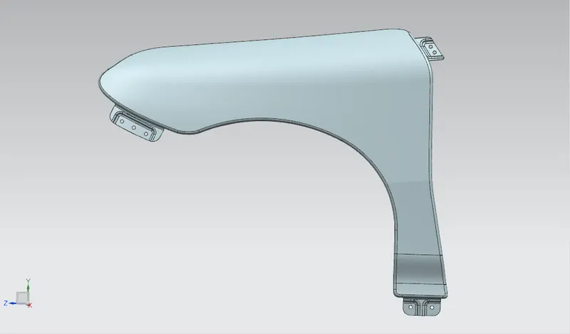
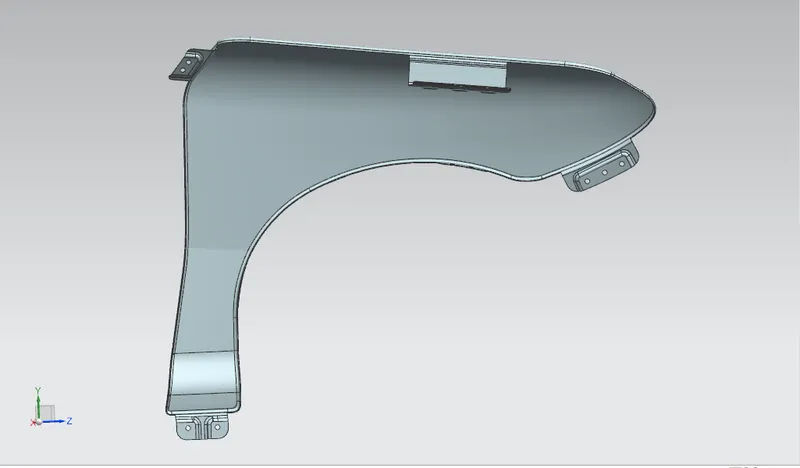
ISOMETRIC VIEWS
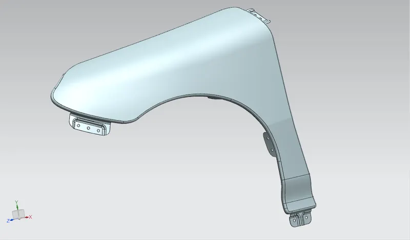
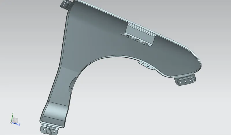
MANUFATURING PROCESS OF FENDER
- Modern vehicles today are equipped with fenders made from plastic, steel, aluminum, and modern plastic composites like thermoplastic and fiberglass. Usually, heavy vehicles like trucks, utility vehicles, and SUVs are equipped with metal or steel fenders, whereas passenger vehicles have plastic fenders
- Sheetmetal generally comes in three forms—mild steel, aluminum, and stainless steel. Of these, aluminum and mild steel are by far the most commonly used for automotive projects.
- One of the most important things about metal is that it can undergo plastic deformation. That doesn't mean metal is made out of plastic, but it can do one of the things that plastics can: It literally can take on almost any shape that we can imagine.
- The process of deformation begins with a blank, a quantity of metal in some basic form that will undergo the change in shape. The blank becomes the workpiece -- the piece of metal to be reshaped -- in the metal forming process. For automotive metal forming, the blank is often made of sheet metal, which can be stamped, cut or bent into a shape needed for an automobile's body. Alternatively, it can be a solid block of metal in a cubical or lens-like shape. Here are some ways that a metal workpiece can be deformed during the automotive manufacturing process:
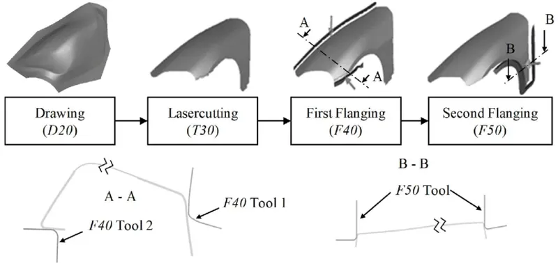
Bending: In bending, force is applied to a sheet metal workpiece to produce a curvature of the surface. Bending is generally used to produce simple curved surfaces rather than complex ones. A mechanically operated press drives a punch against sheet metal, forcing it into a simple die with enough pressure to produce a permanent change in the metal's shape. The amount of pressure is important. If not enough pressure is applied, the metal can simply spring back into its original shape. If too much is applied, it can break.
Drawing: In drawing, the sheet metal is forced against a die that has been cut into the three-dimensional, often curved shape that the sheet metal is to take on. In effect, the die is used as a mold for the metal. This technique can produce relatively complex shapes. Once again, pressure is applied to the workpiece using a hydraulically or mechanically operated punch. There are a number of dangers involved, not so much to people (since the process is largely mechanized) but to the metal itself. It can crack from too much pressure or wrinkle from its interaction with the die. Lubricant can be used to make the metal slide more smoothly against the die, avoiding the possibility of wrinkling. Alternatively, the wrinkled edges can be trimmed from the metal in a separate operation. This method is commonly used to make auto body parts and fuel tanks.
Stamping: In stamping, a device called a stamping press is used with a series of dies to cut and form metal into various shapes. This is commonly used to make auto parts such as hubcaps and fenders.
Extrusion: Extrusion can be used to produce long metal objects, such as rods and tubes. The metal workpiece is forced into a die with a hole in the opposite end. The metal is extruded through the hole to form the shape. Extrusion can be used to manufacture important parts of a car's drive train or the anchors that hold seatbelts in place.
Forging: The forging process uses a hammer or press that is essentially a mechanized version of the hammers used by ancient blacksmiths. The metal is hammered against a surface that serves as an anvil. It can be hammered repeatedly so as to form complex shapes. This can be used as an alternative to the drawing process.
The above processes are generally used with cold metal. Hot metal can also be used, sometimes at high enough temperatures that the molten metal can be poured into a die. This requires very expensive dies that can withstand the heat and must be done quickly, to minimize the exposure of the die to the molten metal.