Wiring harness routing & packaging Rules Week 3 Challenge
WIRING HARNESS ROUTING & PACKAGING RULES WEEK 3 CHALLENGE
IN THIS REPORT:
1. Downloading the P Clamp cad data from given link & defining it as Electrical support using Electrical Part design Workbench. Defining all the necessary properties.
2. Downloading the Back shell cad data from given link (te.com) & defining it as Electrical back shell using Electrical Part design Workbench. Defining all the necessary properties.
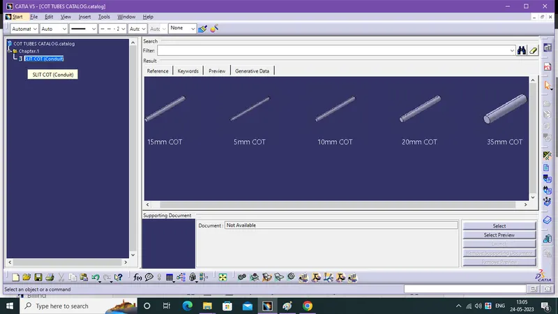
3. Creation of Following Corrugated tubes & Add them into Catalogue under “Slit COT” family.
|
Name |
ID (mm) |
OD (mm) |
Thickness (mm) |
|
15mm COT |
12 |
15 |
1.5 |
|
20mm COT |
17 |
20 |
1.5 |
|
35mm COT |
32 |
35 |
1.5 |
|
10mm COT |
7 |
10 |
1.5 |
|
5mm COT |
3 |
5 |
1 |
*create a axis system similarly as a parent mating product.
1. Downloading the P Clamp cad data from given link & defining it as Electrical support using Electrical Part design Workbench. Defining all the necessary properties:
P - CLAMP
PART WORKBENCH:
- Start from mechanical part workbench, create the couple of points in middle of the two sides (p-clamp).
- create the two planes based on the two points,these two points and planes are bifunctionally work as entry and exit ways of wire bundles.
- clamps had the two entry and two exit ways bifunctionally..
- additionaly create a base palne.
ELECTRICAL PART WORKBENCH: (SUPPORT DEFINTION)
- In this workbench mechanical part is converted into eclectrical support part.
- click a support definition and enter the data point.1, plane.1 in first plane defintion and plane.2 in second plane definition, plane.3 (base plane) in base plane definition.
- do again the support defintion, this time replace point.1, plane.1 by point.2, plane.2 then second plane is taken automatically from first support definition, and select a base plane.
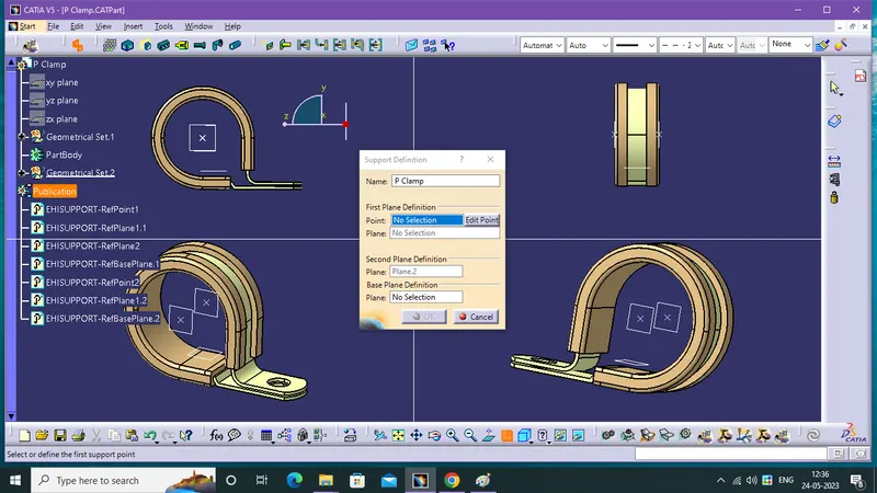
*if you face any issue with point definition, point selection, Right-click on the point definition window and use the reset option.
2. Downloading the Back shell cad data from given link (te.com) & defining it as Electrical back shell using Electrical Part design Workbench. Defining all the necessary properties:
BACKSHELL C-1738312-1
PART WORKBENCH:
- Create a point in the middle of the mating face of the backshell and create a axis system based on that point.
- create a bundle entry point in the middle of the bundle entry face.
ELECTRICAL PART WORKBENCH: (BACK SHELL DEFINTION)
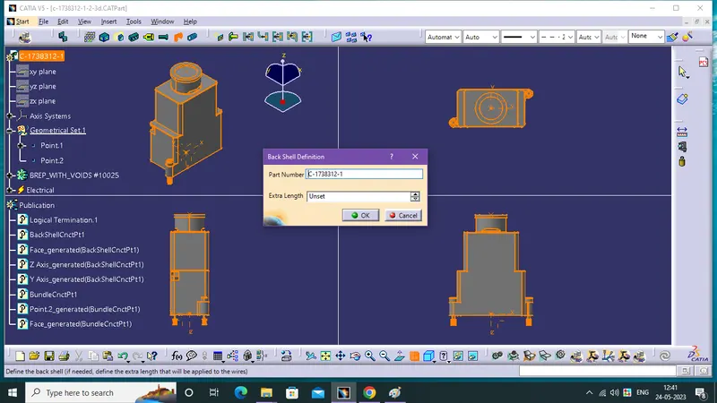
- Click the Back Shell definition and select the backsell then click a ok. now, mechanical part modified into electrical part.
ELECTRICAL PART WORKBENCH: (BACK SHELL CONNECTION POINT)
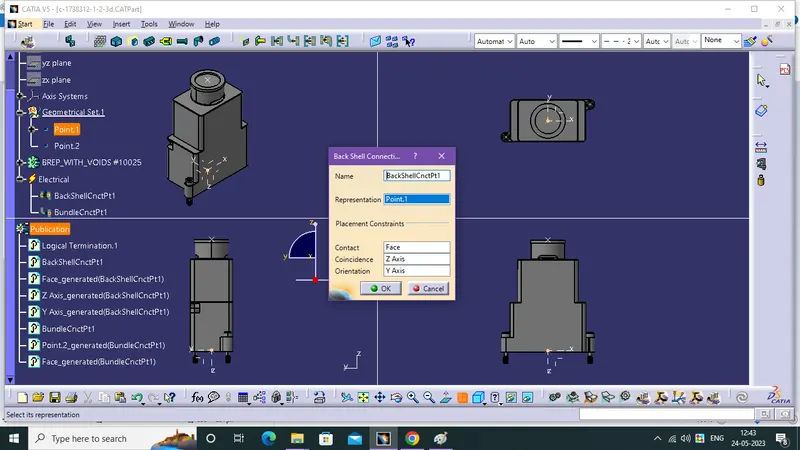
- Click a Back Shell Connection Point, enter the data.
ELECTRICAL PART WORKBENCH: (BUNDLE CONNECTION POINT)
- Click a Bundle Connection Point Definition, enter the data.
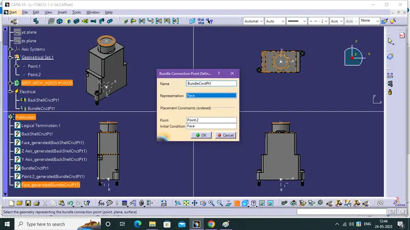
3. Creation of Corrugated tubes & Add them into Catalogue under “Slit COT” family:
35mm COT
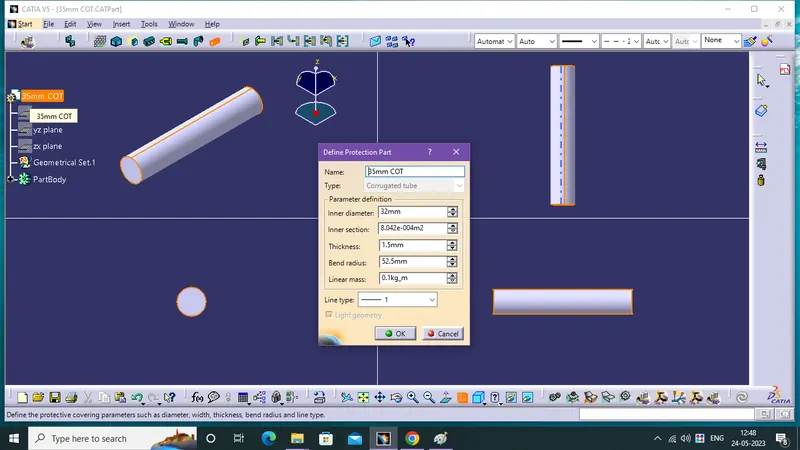
ELECTRICAL PART WORKBENCH: (DEFINE PROTECTION PART)
- Start from the Electrical Part WB, click the Define Protection Part and select the part file then automatically dialog box is opened there.
- Enter the name, inner dia, thick and bend radii in the dialog box.
- bend radius should be 1.5 times of the outer radii.
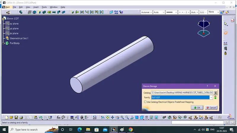
DEVICE STORAGE:
- Click the Device Storage and select a catalog, family then Ok.
COT TUBES CATALOG:
- Catalog reduce the time consuming in designing.
- It is maintaing data of work done catpart, if its here there is no need to start a design from scratch.
- Infrastructure setting is one time effort from design engineer it gives more benefits.
- All Five Cot Tubes are created and saved in the 'SLIT COT' catalog successfully.