Projefct 1_Comparative study of different storey buildings for Seismic forces
AIM :-
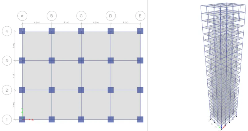
- To model 10 different buildings on ETABS with given structural properties and names as provided in the below picture.
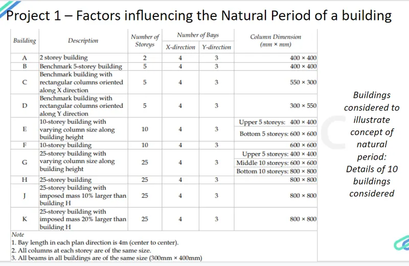
- To compare fundamental natural periods of buildings E & F as well as G & H and find why is there a marginal or significant difference in the fundamental natural periods.
- To Compare fundamental natural periods of buildings H, J and K and to find if the buildings have become more flexible or stiff due to change in mass.
- To observe how do the fundamental natural periods of Buildings A, B, F and H change with change in building height.
- To find how does the fundamental natural periods of Buildings B, C and D change with change in column orientation.
- To compare the fundamental mode shape of Building B in two situations when flexural stiffness of beams relative to that of adjoining columns is very small versus when it is large.
- To compare the fundamental mode shape of Building H in two situations when the axial cross-sectional area of columns is very small versus when it is large.
- To compare the fundamental mode shape of Building B in two situations when the base of columns is pinned versus when it is fixed.
GIVEN :-
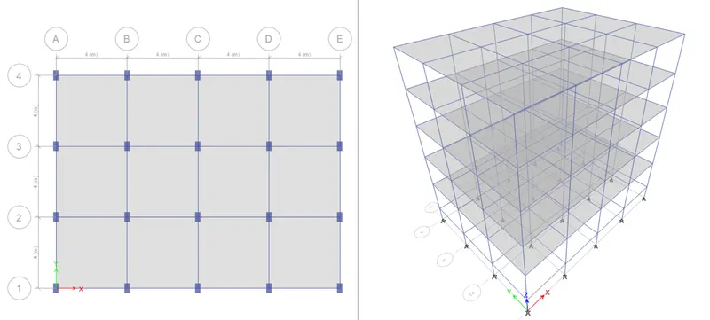
- The grid system for each building is as follow :-
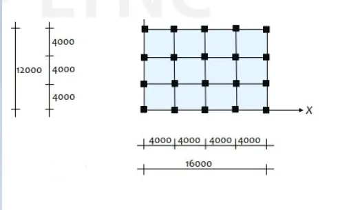
Structural Element Sizes :-
- Beams : 300 × 400 mm
- Columns : columns sizes vary for each building.
- Slab : 150 mm thick
Material Properties :-
- Grade of Concrete : M30
- Grade of Steel Reinforcement Bars : Fe 415
Loads :-
- Dead Load on beams from infill wall = 10 kN/m (Assume the same for roof floor in view of parapet)
- Live load on floor = 3 kN/`m^2`. (Assume the same for roof floor)
PROCEDURE :-
Steps for modelling of "Project Building A" :-
Step 1 :-
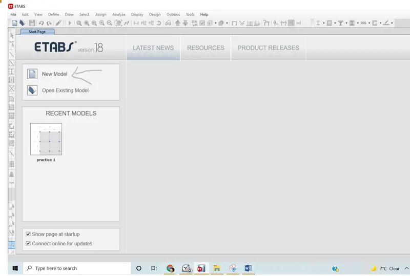
- Open the ETAB software and click on "New Model".
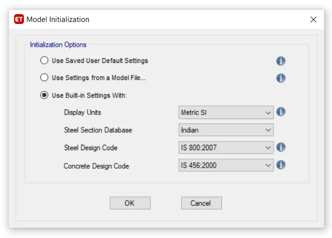
- "Model initialization" dialogue box will open.
- Go to the "Built-in Settings With" option and change the different options as "Select Display unit > Metric SI", "Steel Section Database > Indian", "Steel Design Code > IS 800:2007", "Concrete Design Code > IS 456:2000".
Step 2 :- Creating grids and storeys
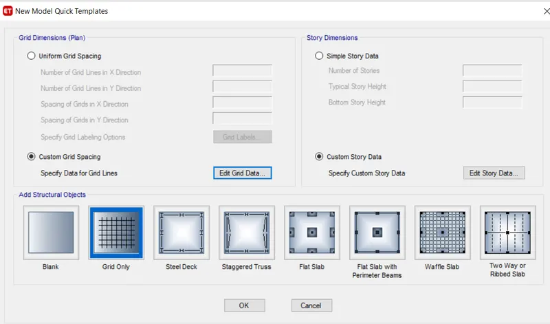
- The "New Model Quick Template" dialogue box will open.
- Check the "Custom Grid Spacing" and click on "Edit Grid data".
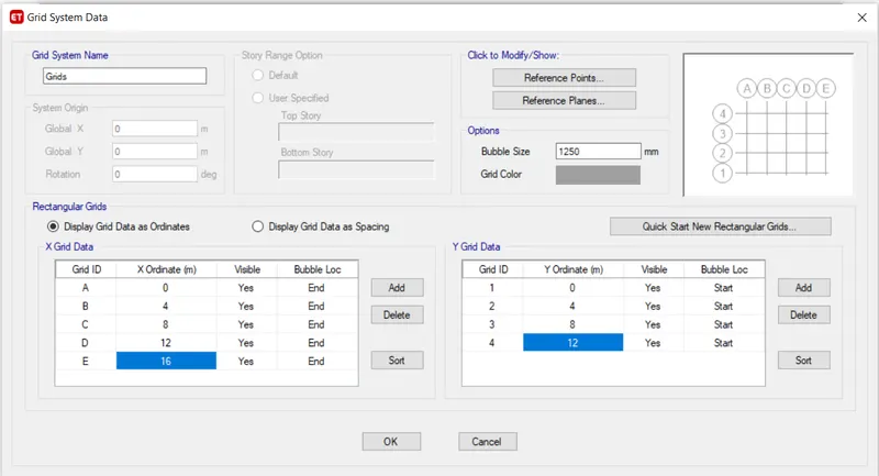
- The "Grid System Data" dialogue box will open.
- Check on the "Display grid data as ordinates" option and provide the grid's data as given for building "A" and then click "OK".
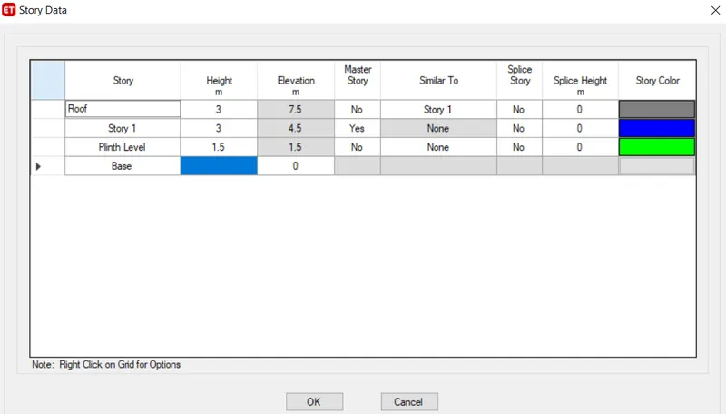
- Now check the "Custom Story Data" and click on "Edit Story data".
- The "Story Data" dialogue box will open.
- Click on "Story1" and rename it as "Plinth Level" and give plinth level height as 1.5m.
- Click on "Story2" and rename it as "Story 1" and give storey height as 3m.
- Again click "Story3" and rename it as "Story 2" and give storey height as 3m.
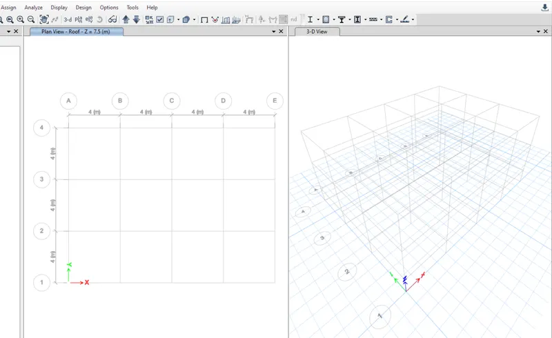
- The following result will shown :-
Step 3 :- Adding Materials
- Close all viewports and select Plan view and on "Storey 1" viewport on the window.
- To select the material, Go to the "define" tab and Select "Material Properties".
- Click on "Add new material". Select Region as "India", Material Type as "Concrete", Standard as "Indian" and Grade as "M30" and then click "OK".
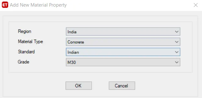
- The "Material Property Data" dialogue box will open.
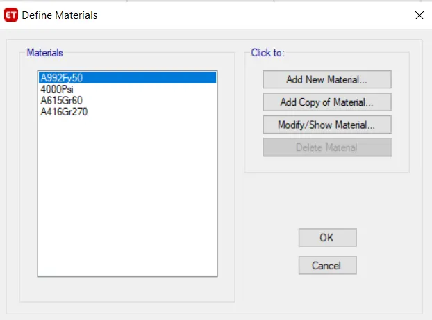
- Click on the "Add New Material" option and add "M30" concrete material to it.
- Check the Data as per requirement or modify it accordingly.
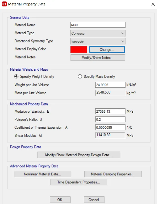
- Click "OK". The concrete material is added.
- Again go to the "Add New Material" option and add the rebar for longitudinal reinforcement.
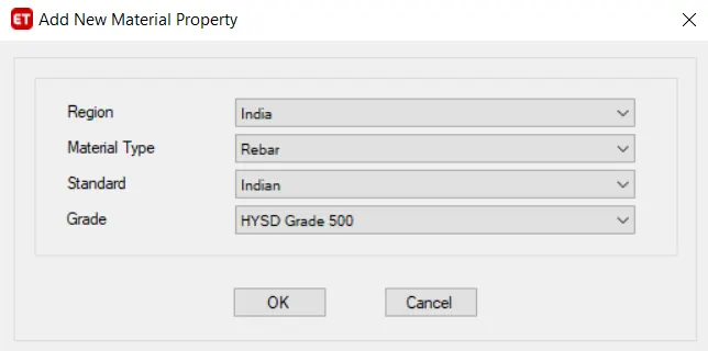
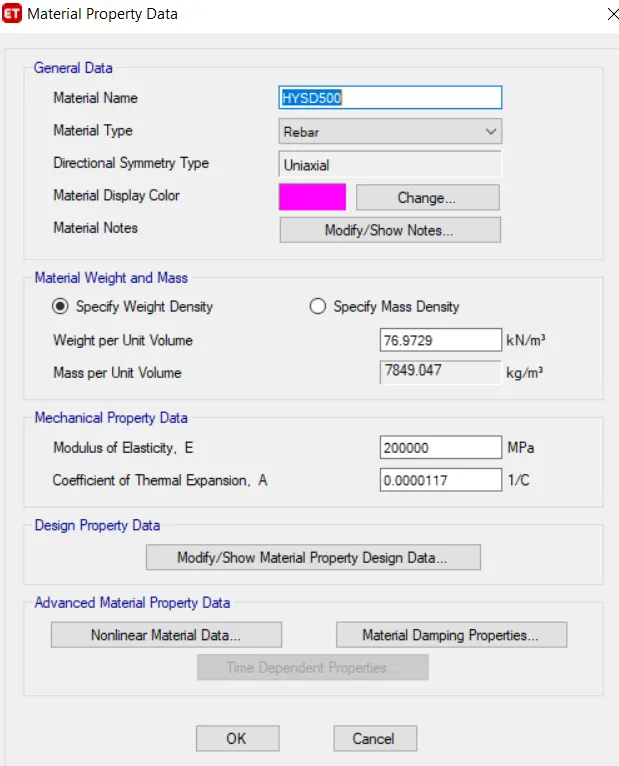
- Provide the data requirement and then click "OK".
- Similarly, add the shear reinforcement.
- Provide "grade 415" for shear reinforcement.
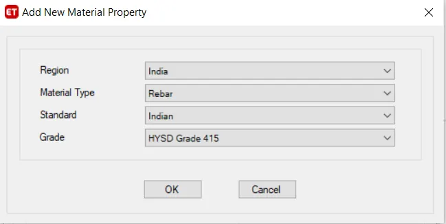
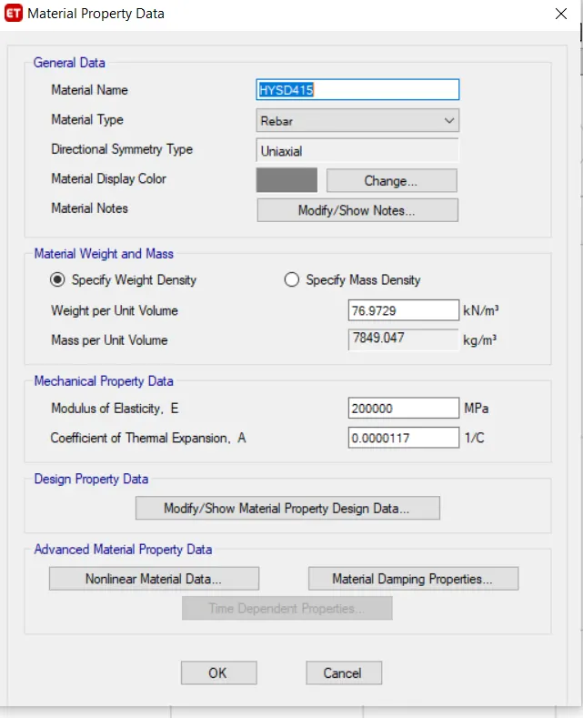
- Click "OK".
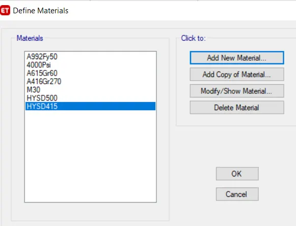
Step 4 :- Adding Columns, Beams and Slabs
- For beam, Go to the "Define" tab and Select "Section properties Select" and then click on "Frame sections".
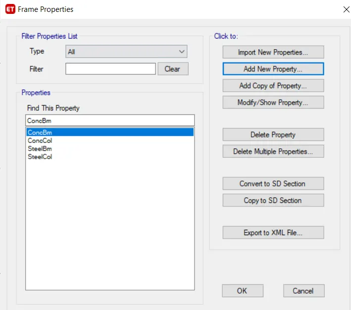
- Click on "Add New Property".
- Select "Rectangular concrete".
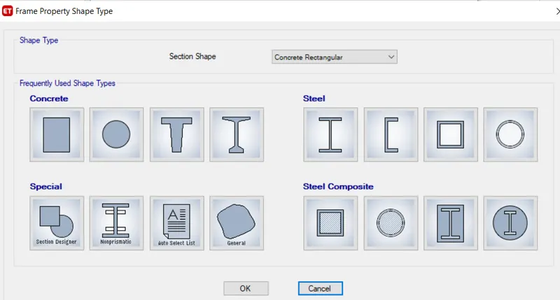
- Change Property name to "B- 300 X 400"
- Provide Material "M30" and give dimensions as "Depth = 400" and "Width = 300".
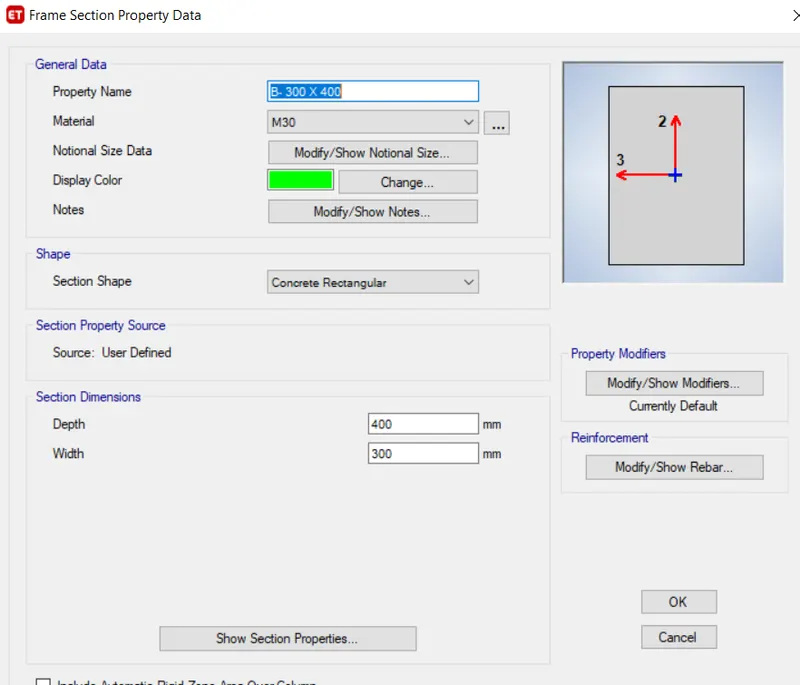
- Keep all other properties as default.
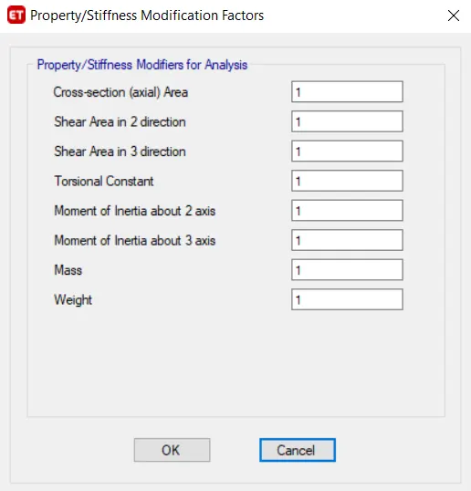
- Select "Modify rebar" and fill in the data as per requirement.
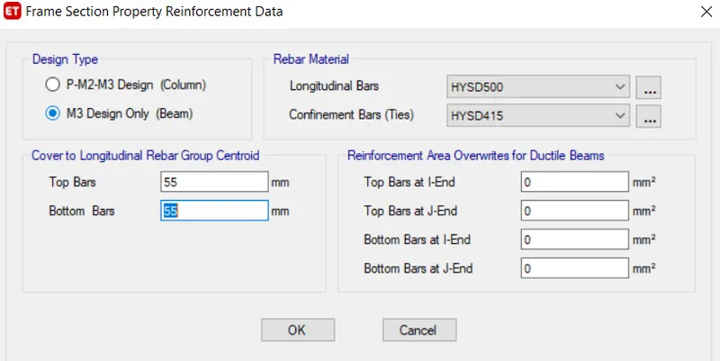
- Click "OK" and the beam is added.
- Now, add another element "Column" by Clicking on "Add new property".
- Select "Rectangular concrete", Rename Property name as "C- 400 X 400", provide Material "M30" and give section dimension as "Depth = 400" and "Width = 400".
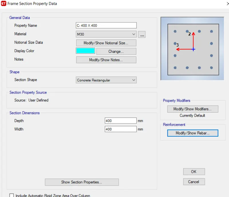
- Select "Modify rebar" and Fill in the data as per requirement.
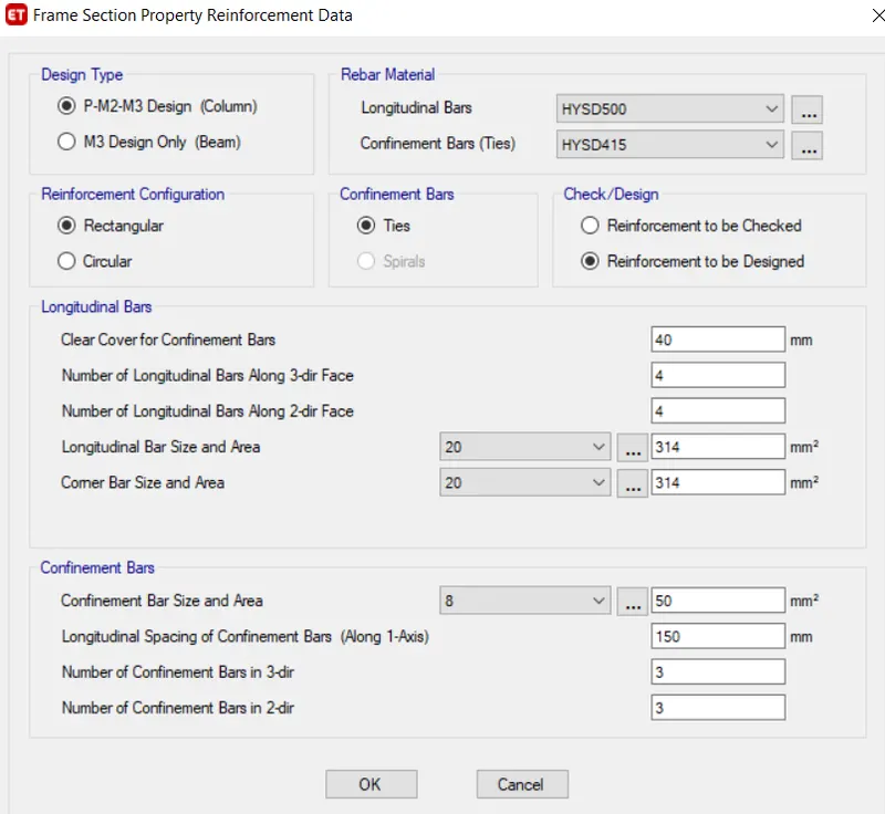
- Keep all other properties as default.
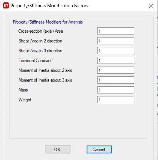
- Click "Ok" and the column is added.
- Now for Slab, Go to the "define" tab and Select "Section properties" then Select the "Slab section".
- Click on "Add New Property".
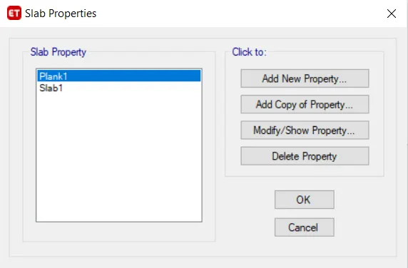
- Change Property name as "Slab 150", Slab material as "M30" and Modeling type as "Membrane" and provide the thickness of slab as 150mm.
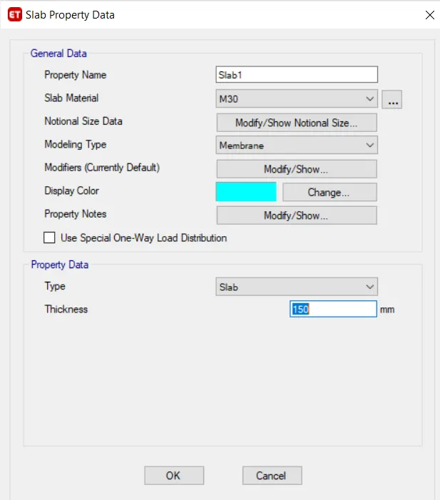
- Click "OK" and the Slab is added.
Step 5 :- Drawing Columns, Beams and Slabs
Drawing Columns :-
- Go to the Plan view of Story 1 and select the "All story" option at the bottom.
- Take the "Quick Draw Column" command and select the column "C- 400 X 400".
-
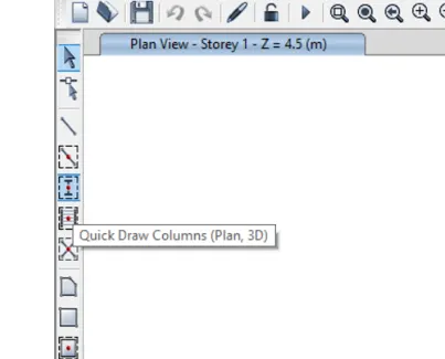
- Provide the columns, by clicking on all the intersection points of grids.
-
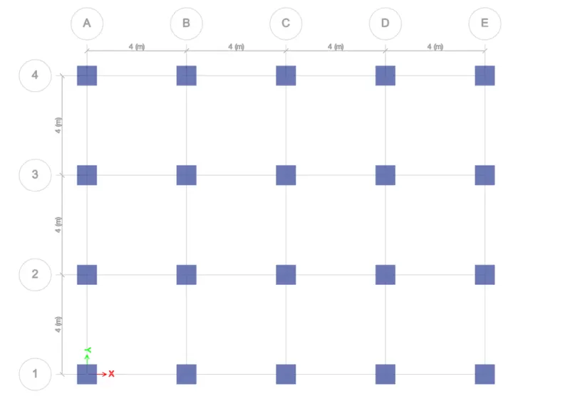
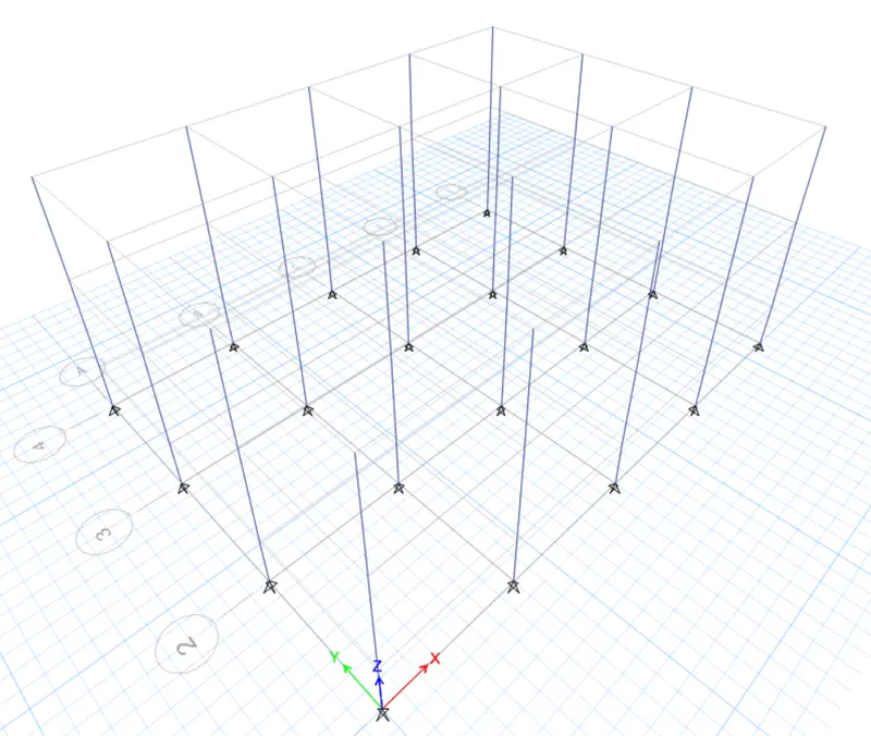
- Check the final result in the 3D view as well.
Drawing Beams :-
- Again open the first story plan view and select the "All story" option at the bottom.
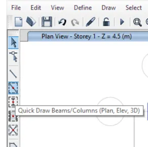
- Go to the "Quick Draw Beam" command and Select Beam "B- 300 x 400".
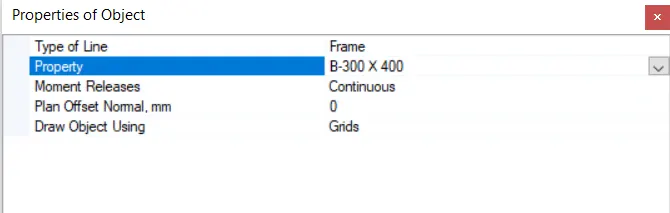
- Click on all grid lines in between columns to provide the beams.
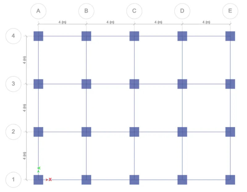
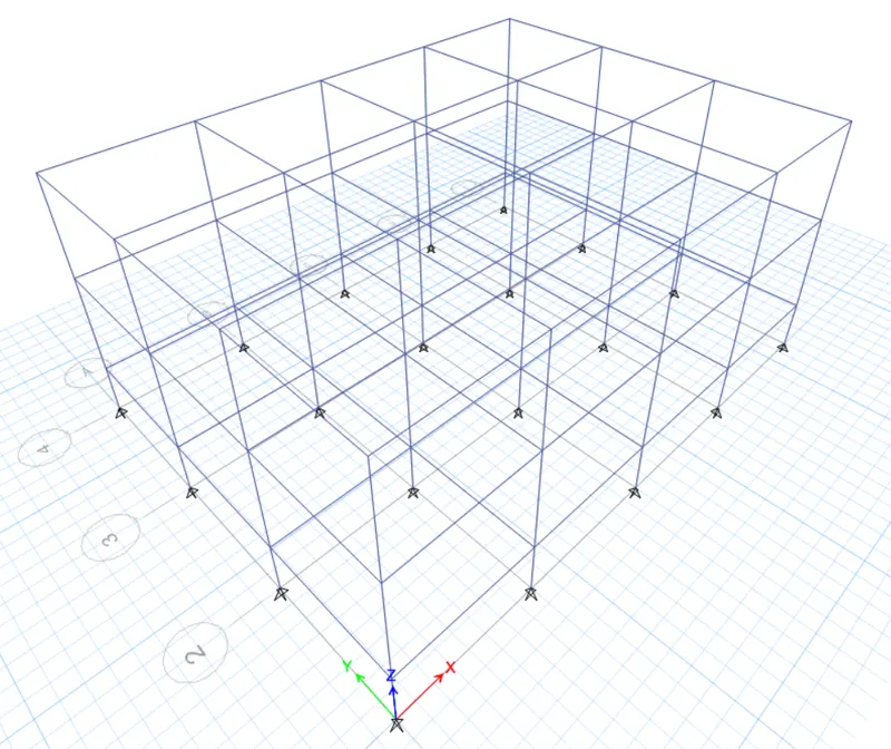
- Check the final result in the 3D view as well.
Drawing Slabs :-
- Again open the first story plan view and select the "Similar story" option at the bottom.
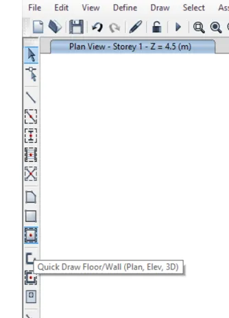
- Click on the "Quick Draw Floor" command and Select Slab "Slab 150".
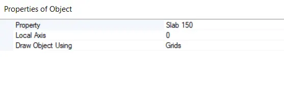
- Now click in between grids where the slab is to be provided.
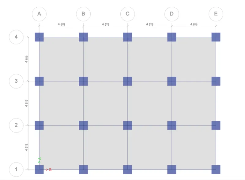
- Check the final result in the 3D view as well.
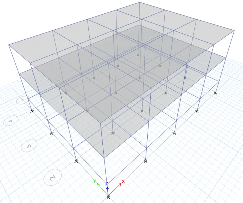
Step 6 :- Adding Support
- The building is assumed to be pinned at the base.
- For assigning pinned support, go to plan view and select "Base plan".
- Select the "One Story" option at the bottom.
- Select all the joints and then click on the "Assign" tab and Select "Joints" then Select "Restraints" and Select the base as "Pinned".
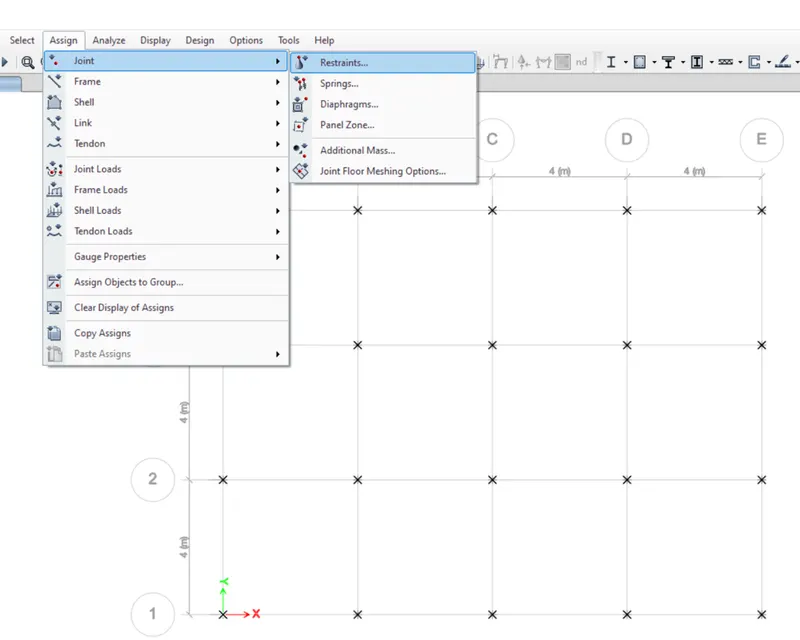
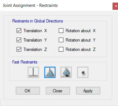
- Click "Apply" and then click "OK".
Step 7 :- Adding Load Pattern
- Click on the "Define" tab and select "Load patterns"
- Add different loads i.e., Dead load, Live load and Infill wall load.
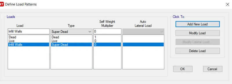
- Click "OK" after adding the loads.
Step 8 :- Assigning Loads to Structural Members
Assigning Live Load to Floors :-
- Open the "Story 1" plan view and select the "Similar story" option at the bottom.
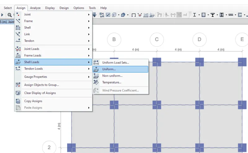
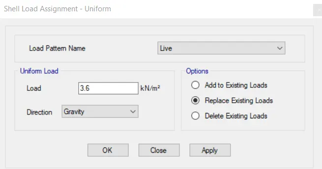
- Select all the shells and then go to the "Assign" tab, then select "Shell loads", and click on "Uniform".
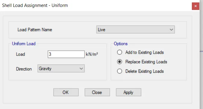
- Give the value of live load as per question requirement.
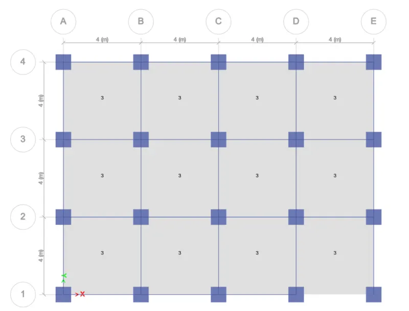
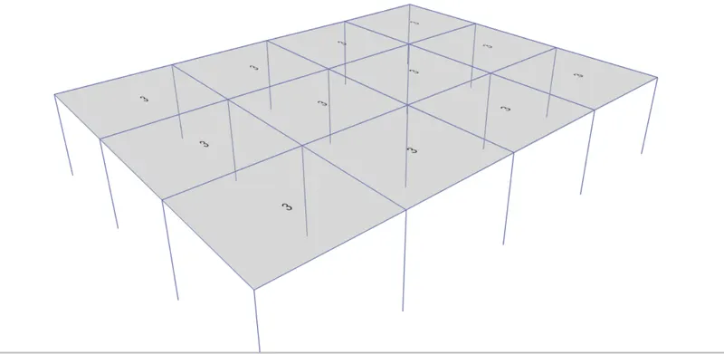
- Perspective view :-
Assigning Infill Walls Load to Beams :-
- Go to the "Select" tab and click on "Object type".
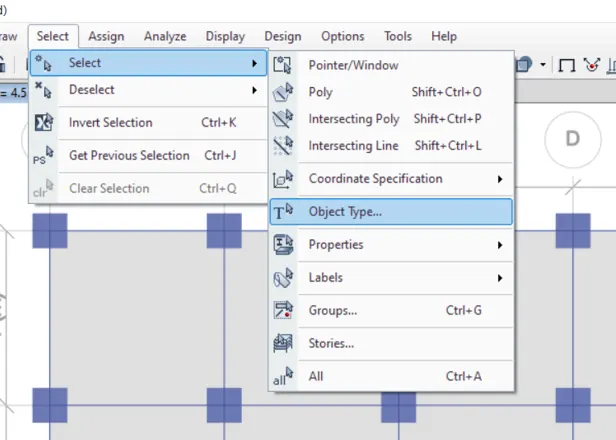
- Now Click on "Beams" and then click "Select"
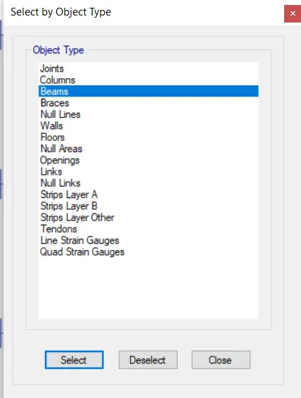
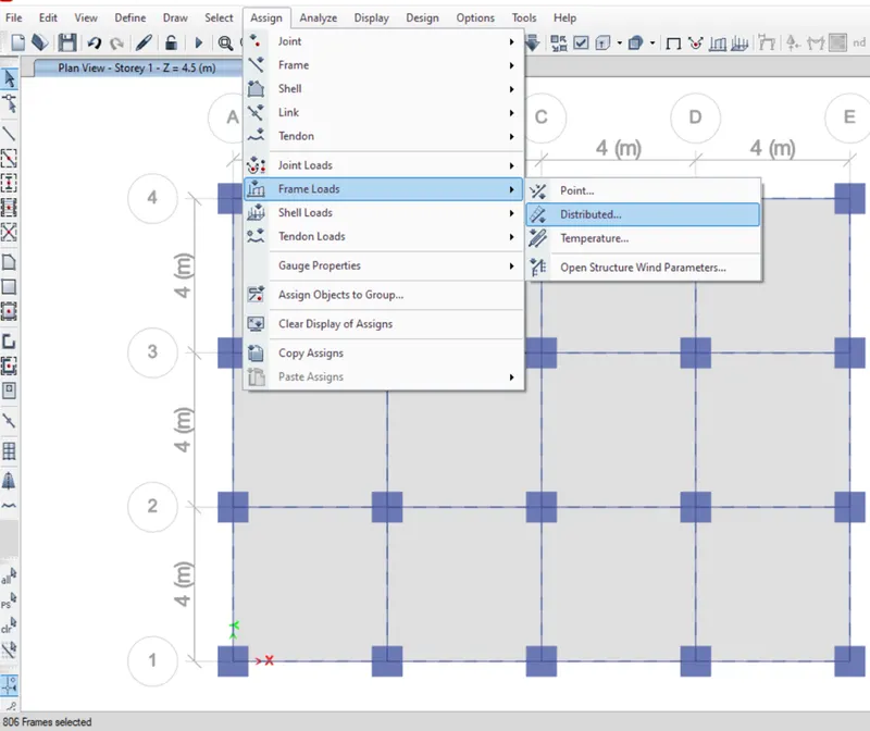
- All the beams are selected and for assurance check the bottom left corner.
- Now go to the "Assign" tab and select "Frame Loads" and then "Distributed".
- Select "Infill Walls" as the load pattern name and give the value of "10 kN/m" in the uniform load section.
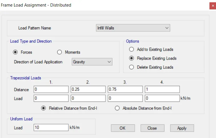
- Click "OK" and then click "Close".
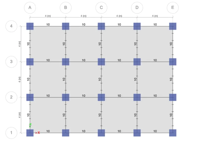
- Perspective view :-
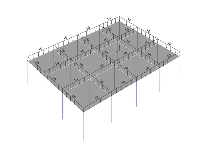
Step 9 :- Assigning the Mass Source
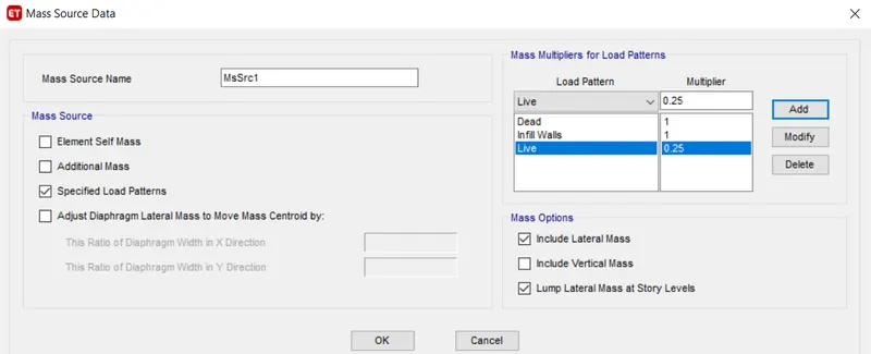
- Go to the "Define" tab and Select "Mass Source".
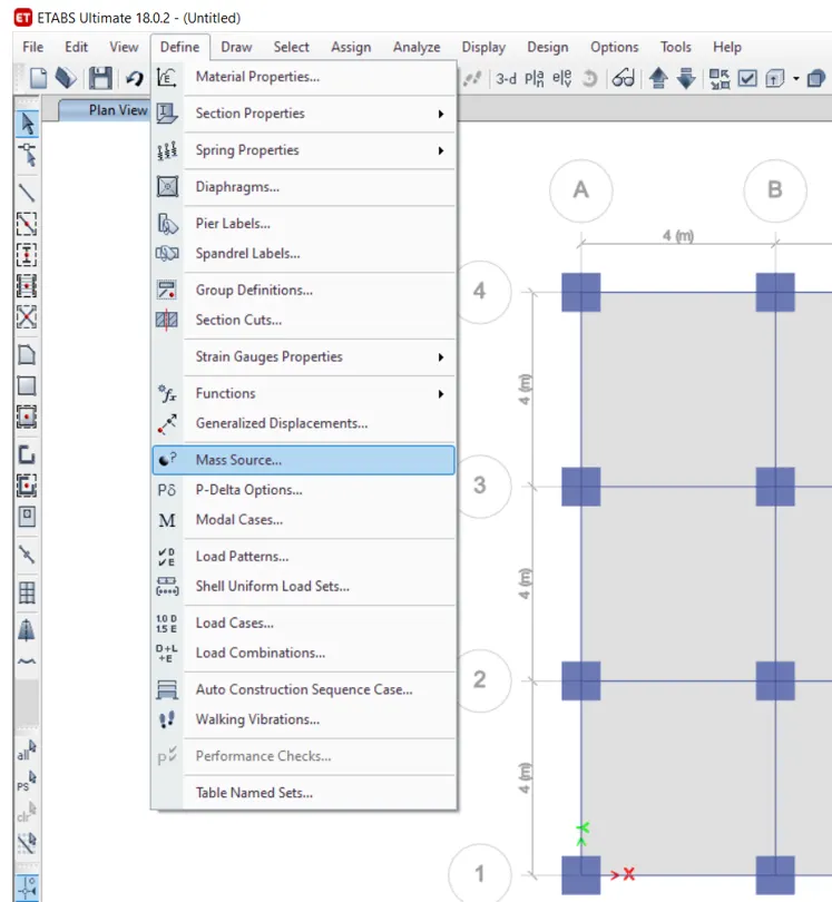
- Select the "Modify/Show mass source" option.
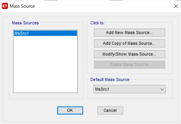
- Define the Seismic mass as per the code and then click "OK".
Step 10 :- Generating the Load combinations
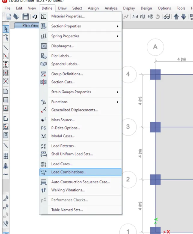
- Go to the "Define" tab and Select "Load Combination".
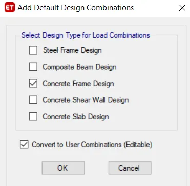
- Click on "Add Default Design Combos".
- Check the "Concrete Frame Design" and "Convert to User Combinations" box and then click "OK".
. 
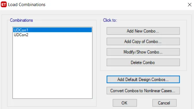
- The load combinations are generated. Click "OK".
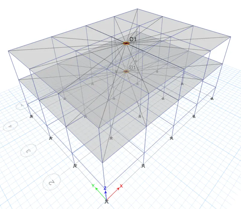
Step 11 :- Assigning the Diaphragm to the Floor
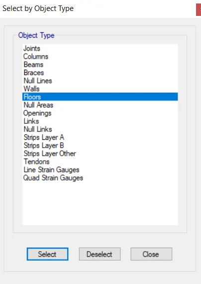
- Go to the "Select" tab and click on "Object type".
- Now Click on "Floors" and then click "Select" and then click on "Close".
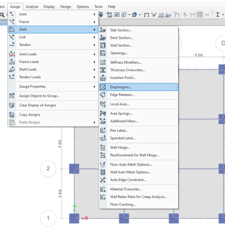
- Now go to the "Assign" tab Select "Shell" and then Click on "Diaphragm".
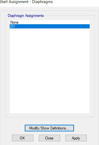
- "Shell Assignment - Diaphragm" dialogue box will open.
- Select "D1" and click on "Apply" and then click "OK". The diaphragms are applied.
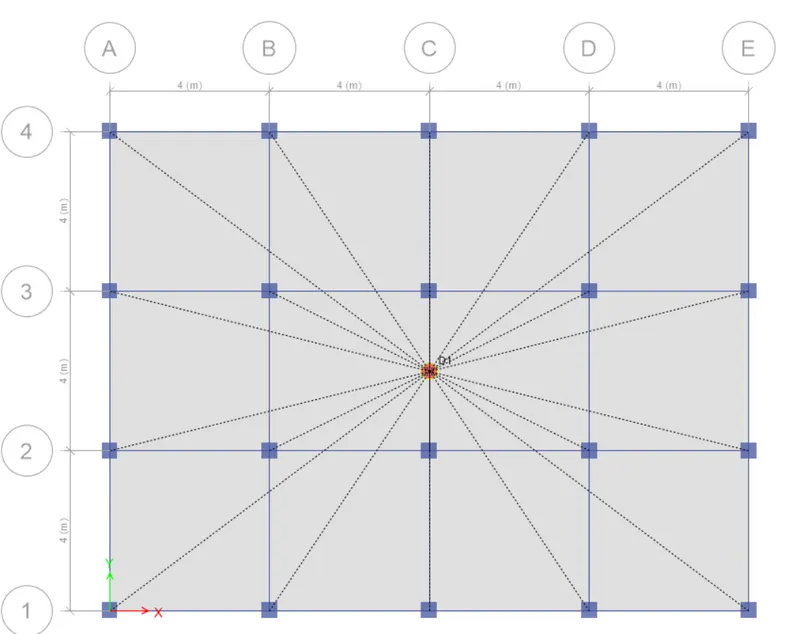
- Check the final result in the 3D view as well.
Step 12 :- Defining Modal Cases
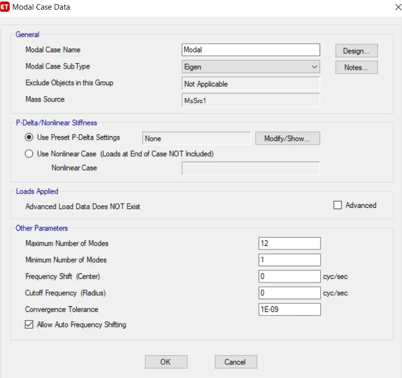
- Go to the "Define" tab and Click on "Modal Cases".
- Click on "Modify/Show Cases" and set the maximum number of modes as per choice.
Step 13 :- Checking Model
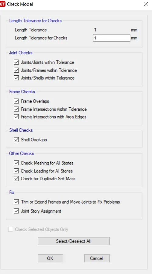
- Go to the "Analyze" tab and click on the "Check the Model" option.
- Select all the checks which are required to be checked and then click "OK".
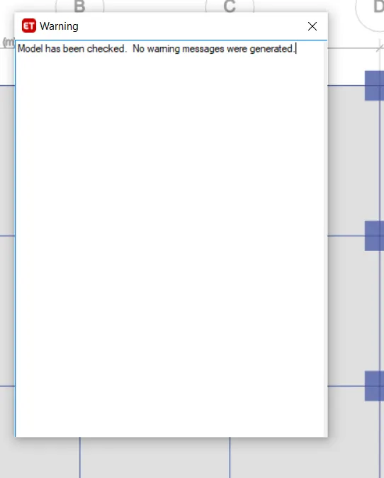
- If "No Warning" arise then the model is ready for analysis.
Step 14 :- Run Analysis
- After checking, click on the "Run Analysis" Icon or press the "F5" function key.
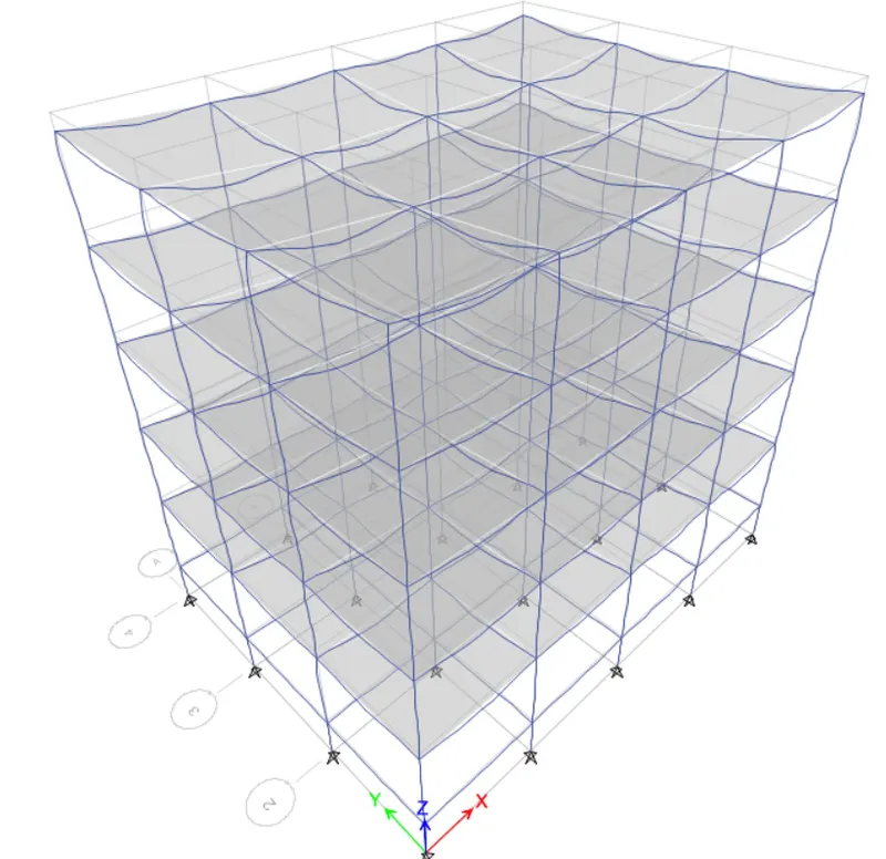
3D View - Displacement :-
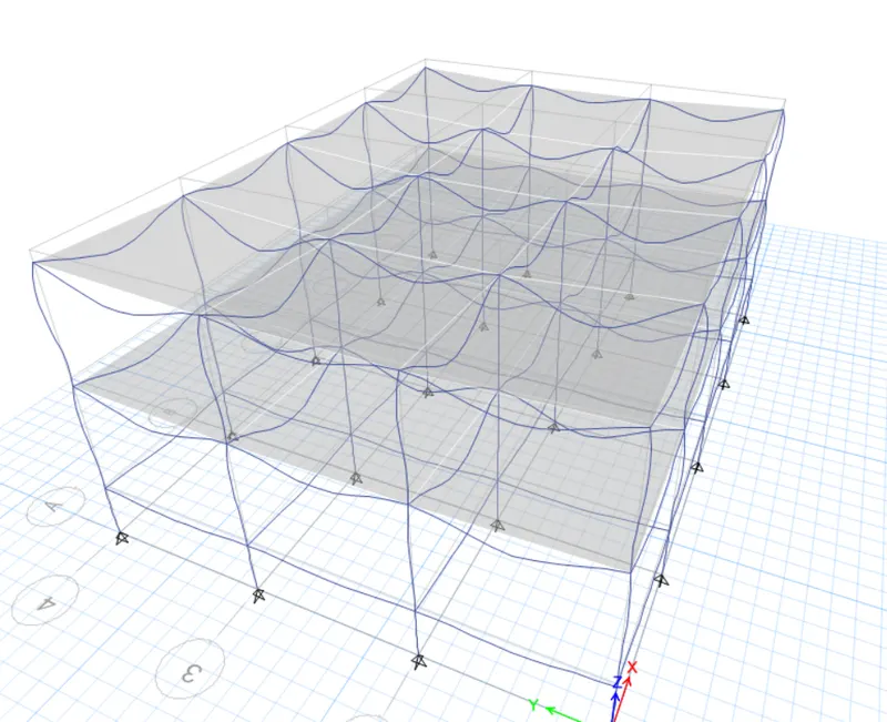
Step 15 :- Checking Deflection
- Click on the "Show Deformed Shapes" icon or press the "F6" function key.
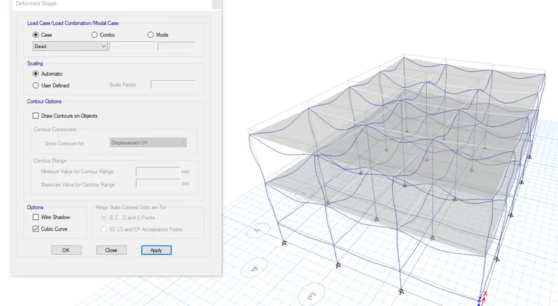
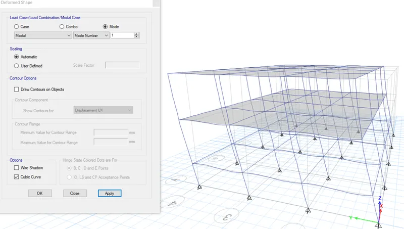
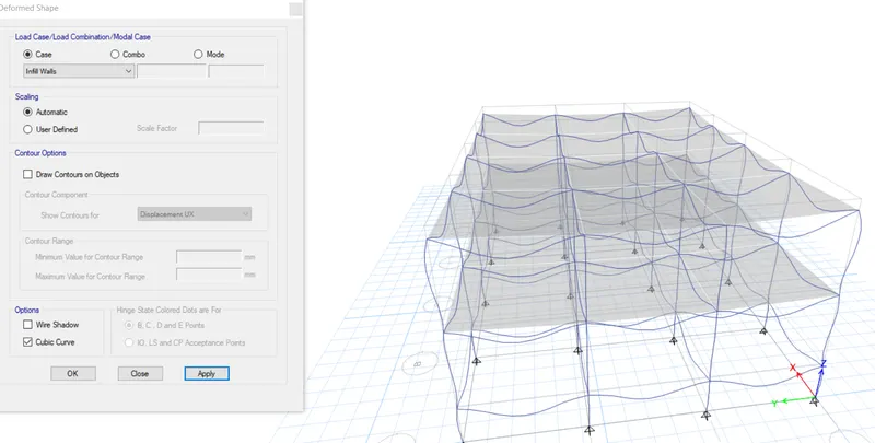
- The "Deformed Shape" dialogue box will open, select the load for which the deflection is required and then click on apply.
Deformed Shape For "Dead Load" Case :-
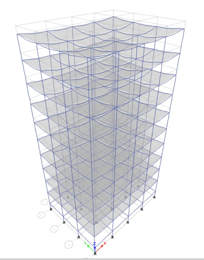
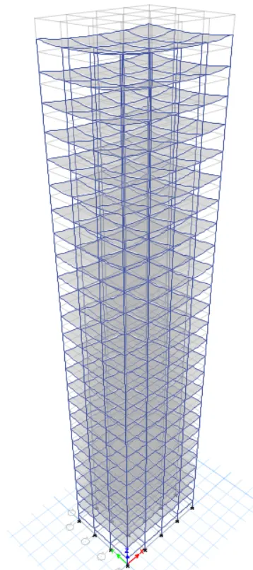
Deformed Shape For "Modal Mode 1" Case :-
Deformed Shape For "Infill Walls Load" Case :-
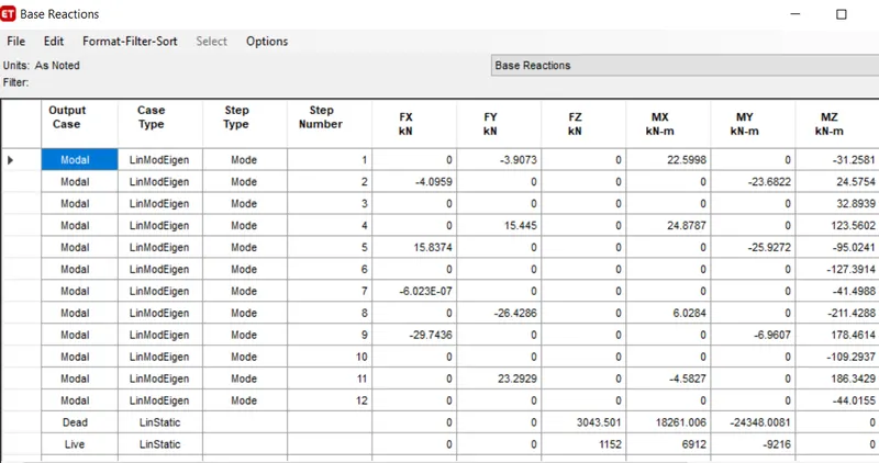
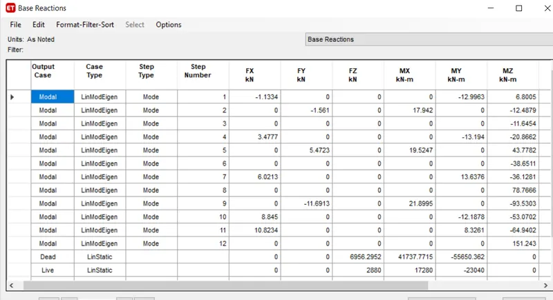
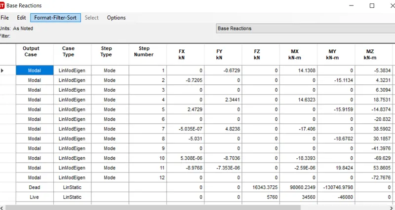
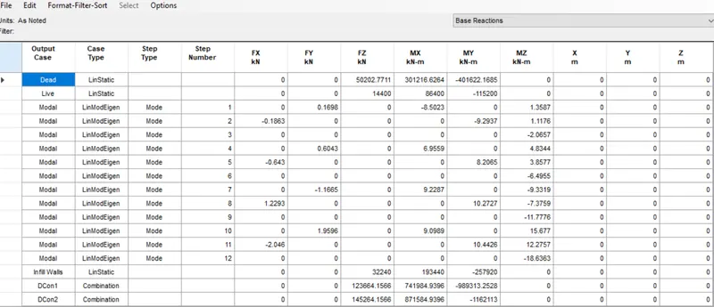
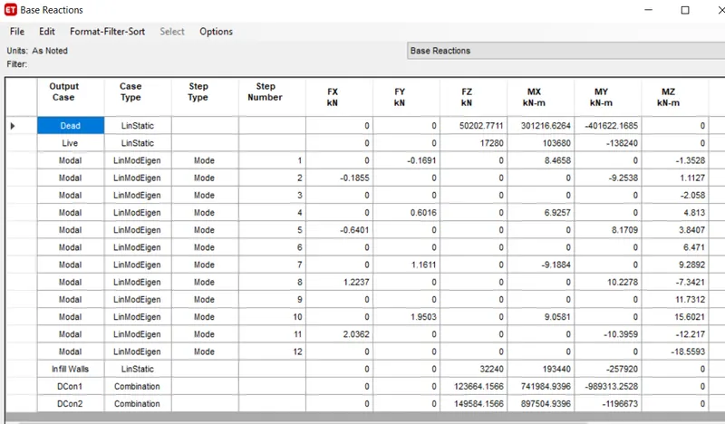
Step 16 :- Checking Base Reactions
- Go to the "Display" tab and select "Show Table".
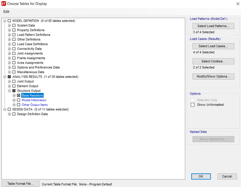
- Select the "Base Reaction" Table and then press "OK".
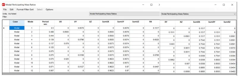
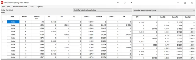
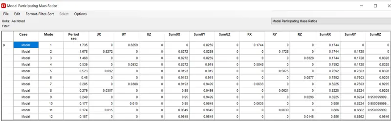
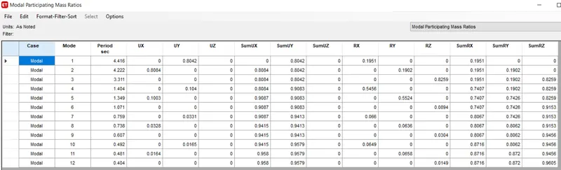
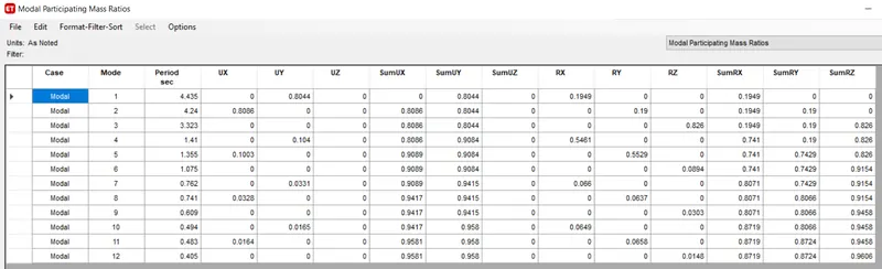
Step 17 :- Checking Modal Results
- Go to the "Display" tab and select "Show Table".
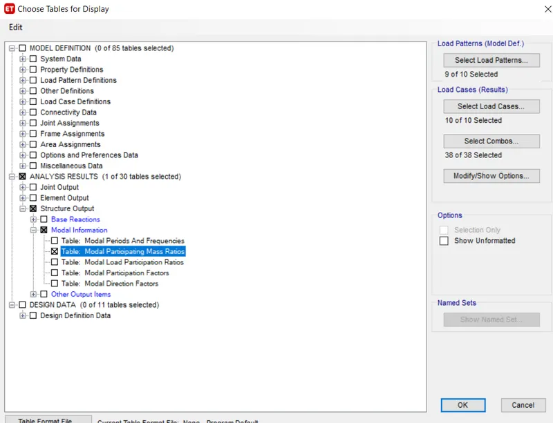
- Select the "Model Participating Mass Ratio" Table and then press "OK".
Modelling of other Buildings :-
- All other buildings are to be modelled the same as Building A.
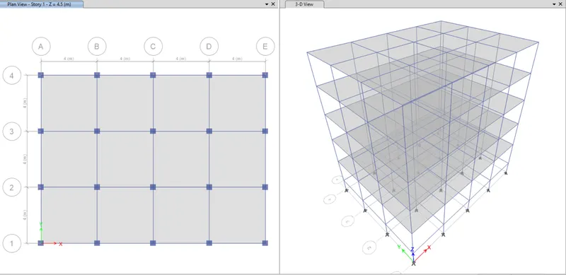
Project Building B :-
- Copy the "Building A" file and paste it on the convenient location of the computer and rename that file as "Building B".
- Now open the newly saved file and make changes in that file on ETABS.
- Add the Stories and add Beam, Slabs and Columns to them as per the question.
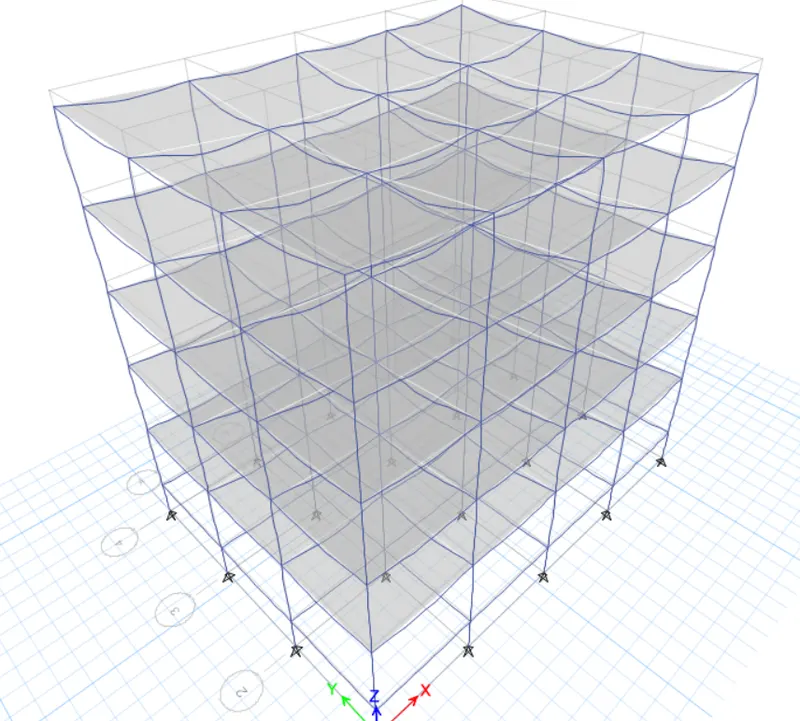
- Run Analyses of the building and check the properties and save them for further comparison.
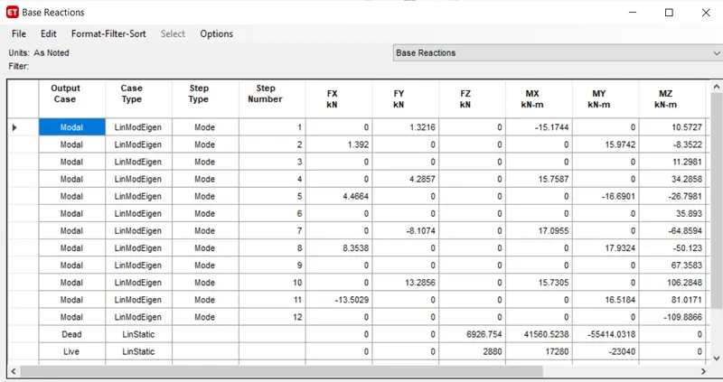
Base Reaction Table for Building "B" :-
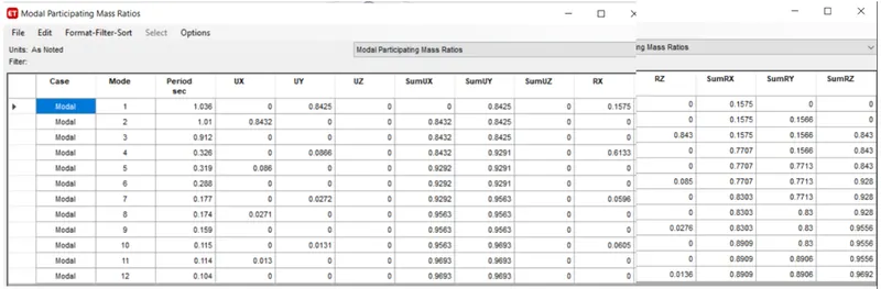
Modal Participating Mass Ratio Table for Building "B" :-
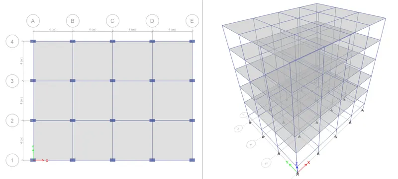
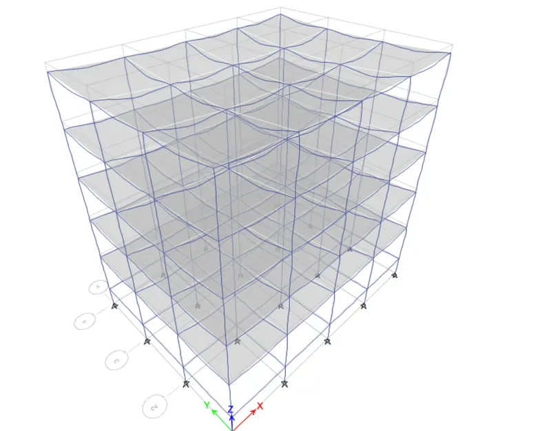
Project Building C :-
- Copy the "Building B" file and paste it on the convenient location of the computer and rename that file as "Building C".
- Now open the newly saved file and make changes in that file on ETABS.
- Add the Stories and add Beam, Slabs and Columns to them as per the question.
- Run Analyses of the building and check the properties and save them for further comparison.
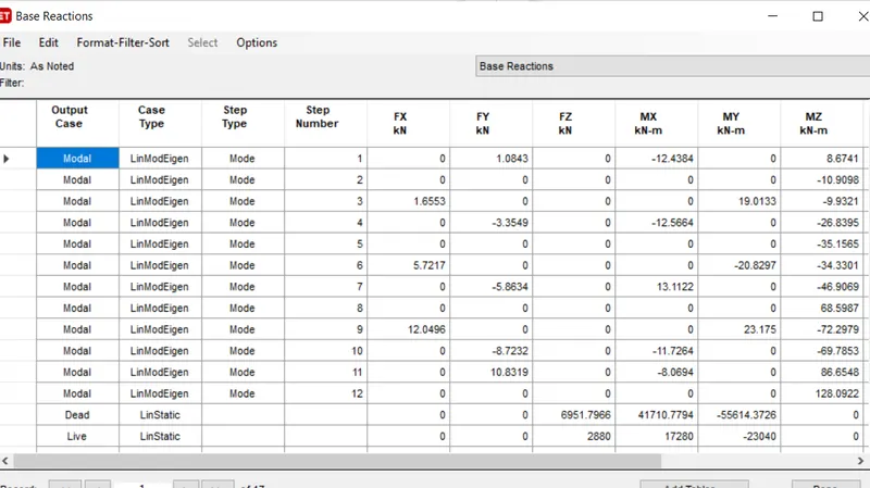
Base Reaction Table for Building "C" :-
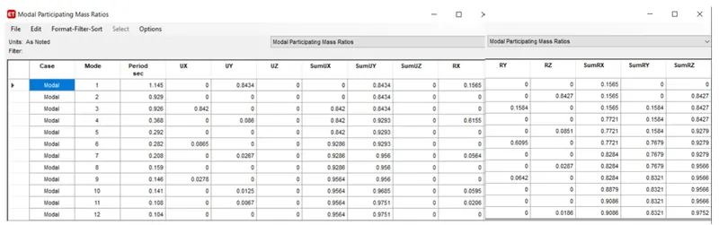
Modal Participating Mass Ratio Table for Building "C" :-
Project Building D :-
- Copy the "Building C" file and paste it on the convenient location of the computer and rename that file as "Building D".
- Now open the newly saved file and make changes in that file on ETABS.
- Add the Stories and add Beam, Slabs and Columns to them as per the question.
- Run Analyses of the building and check the properties and save them for further comparison.
Base Reaction Table for Building "D" :-
Modal Participating Mass Ratio Table for Building "D" :-
Project Building E :-
- Copy the "Building D" file and paste it on the convenient location of the computer and rename that file as "Building E".
- Now open the newly saved file and make changes in that file on ETABS.
- Add the Stories and add Beam, Slabs and Columns to them as per the question.
- Run Analyses of the building and check the properties and save them for further comparison.
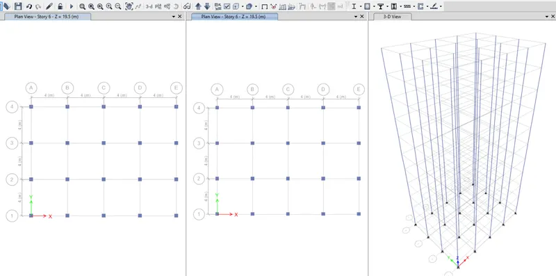
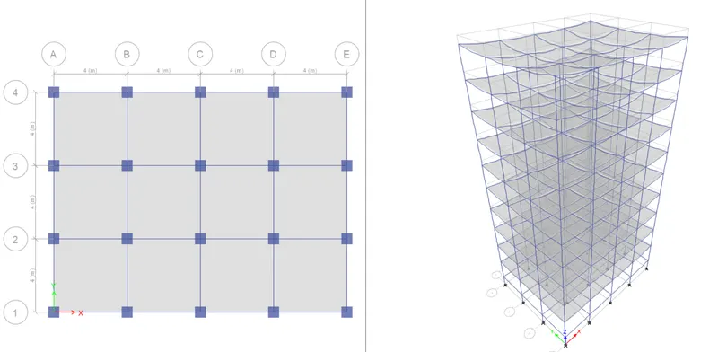
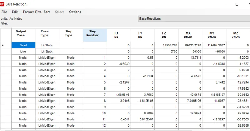
Base Reaction Table for Building "E" :-
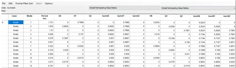
Modal Participating Mass Ratio Table for Building "E" :-
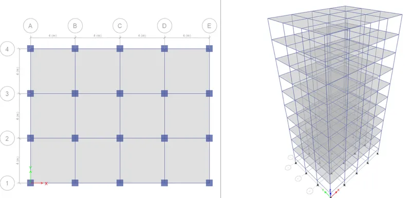
Project Building F :-
- Copy the "Building E" file and paste it on the convenient location of the computer and rename that file as "Building F".
- Now open the newly saved file and make changes in that file on ETABS.
- Add the Stories and add Beam, Slabs and Columns to them as per the question.
- Run Analyses of the building and check the properties and save them for further comparison.
Base Reaction Table for Building "F" :-
Modal Participating Mass Ratio Table for Building "F" :-
Project Building G :-
- Copy the "Building F" file and paste it on the convenient location of the computer and rename that file as "Building G".
- Now open the newly saved file and make changes in that file on ETABS.
- Add the Stories and add Beam, Slabs and Columns to them as per the question.
- Run Analyses of the building and check the properties and save them for further comparison.
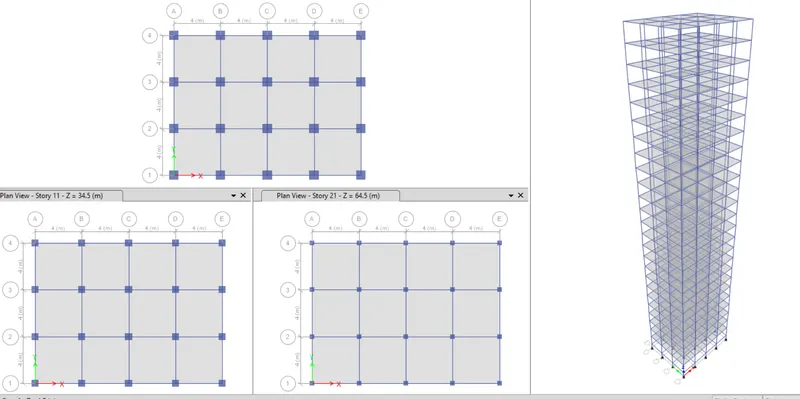
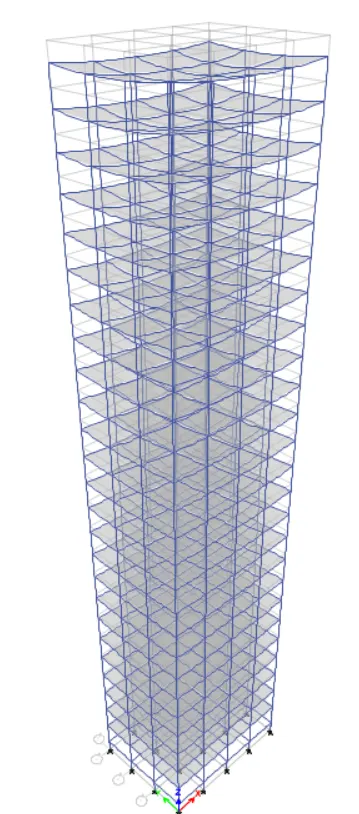
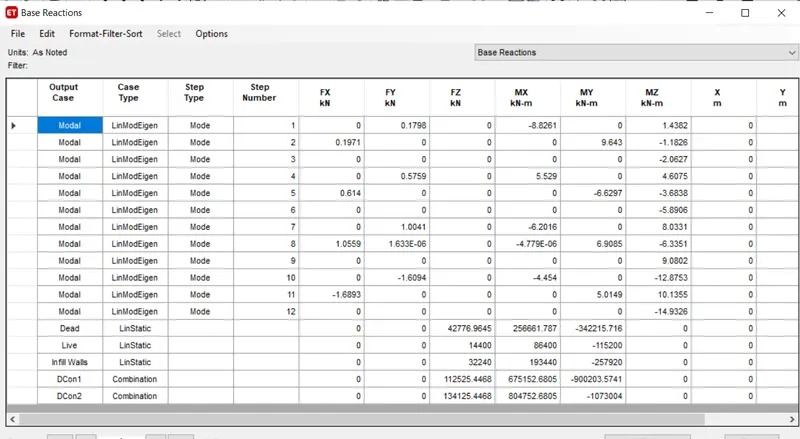
Base Reaction Table for Building "G" :-
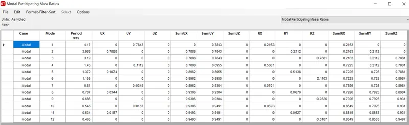
Modal Participating Mass Ratio Table for Building "G" :-
Project Building H :-
- Copy the "Building G" file and paste it on the convenient location of the computer and rename that file as "Building H".
- Now open the newly saved file and make changes in that file on ETABS.
- Add the Stories and add Beam, Slabs and Columns to them as per the question.
- Run Analyses of the building and check the properties and save them for further comparison.
Base Reaction Table for Building "H" :-
Modal Participating Mass Ratio Table for Building "H" :-
Project Building J :-
- Copy the "Building H" file and paste it on the convenient location of the computer and rename that file as "Building J".
- Now open the newly saved file and make changes in that file on ETABS.
- Add the Stories and add Beam, Slabs and Columns to them as per the question.
- Run Analyses of the building and check the properties and save them for further comparison.
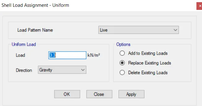
- Increase the imposed load(Live Load) by 10% i.e., 3.3 kN/`m^2`.
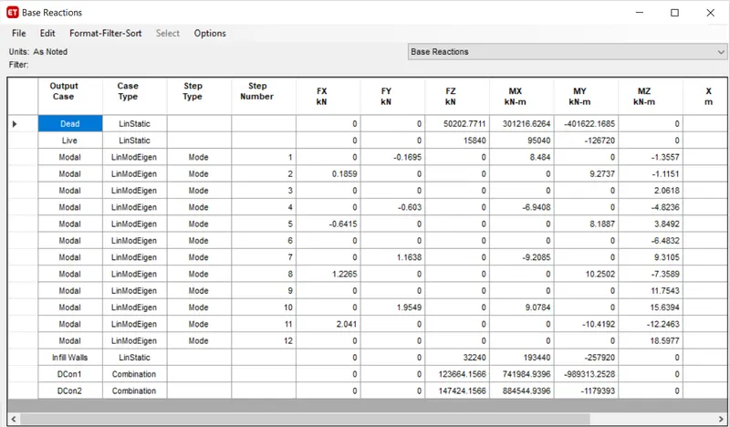
Base Reaction Table for Building "J" :-
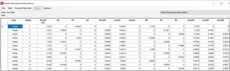
Modal Participating Mass Ratio Table for Building "J" :-
Project Building K :-
- Copy the "Building J" file and paste it on the convenient location of the computer and rename that file as "Building K".
- Now open the newly saved file and make changes in that file on ETABS.
- Add the Stories and add Beam, Slabs and Columns to them as per the question.
- Run Analyses of the building and check the properties and save them for further comparison.
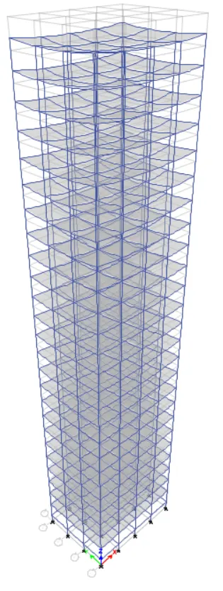
- Increase the imposed load(Live Load) by 20% i.e., 3.6 kN/`m^2`.
Base Reaction Table for Building "K" :-
Modal Participating Mass Ratio Table for Building "K" :-
COMPARISON :-
To compare fundamental natural periods of buildings E & F as well as G & H and find why is there a marginal or significant difference in the fundamental natural periods.
| Building E | Building F | |
|
Tx1 |
1.731 s | 1.735 s |
| Ty1 | 1.676 s | 1.678 |
| Building G | Building H | |
|
Tx1 |
4.17 s | 4.416 s |
| Ty1 | 3.988 s | 4.222 s |
- Here, the time period of Building "F" and building "H" is marginally greater than the building "E" and building "G" because of uniformity in column sizes of building "F" and building "H" throughout the heights.
- The time period is directly proportional to the mass of the building. So, in building "E" and building "F" the mass is increased and thats why it results in increase in the time period.
Tn = 2`pi``sqrt (m/k)`
- The impact on stiffness of the buildings are negligible.
To Compare fundamental natural periods of buildings H, J and K and to find if the buildings have become more flexible or stiffer due to change in mass.
| Building H | Building J | Building K | |
| Tx1 | 4.416 s | 4.425 s | 4.435 s |
| Ty1 | 4.222 s | 4.231 s | 4.24 s |
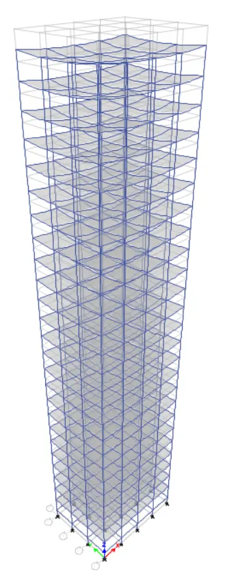
- Here, each building are 25 story building but the Building "J" and Building "K" has 10 % and 20 % more imposed mass than the mass of building "H".
- The time period is directly proportional to the mass of the building, hence, in building "J" and building "K", the mass is increased and thats why it results in increase in the time period.
- More the time period of a building results in the more flexible and so the building "K" and building "J" is more flexible than the building H.
To observe how do the fundamental natural periods of Buildings A, B, F and H change with change in building height.
| Building A | Building B | Building F | Building H | |
| Tx1 | 0.5 s | 1.036 s | 1.735 s | 4.416 s |
| Ty1 | 0.488 s | 1.01 s | 1.678 s | 4.222 s |
- Here, we see that the funamental natural period of buiding is increase with increase in the height of building.
- As the height of the building increases, its mass increases but the overall stiffness will be decreases with increase in height.
To find how does the fundamental natural periods of Buildings B, C and D change with change in column orientation.
| Building B | Building C | Building D | |
| Tx1 | 1.036 s | 1.145 s | 1.12 s |
| Ty1 | 1.01 s | 0.929 s | 0.953 s |
- Here, the buiding "B" has the square columns, so the building B has nearly same natural period along the X axis and along the Y axis.
- In Building C, the columns are oriented along the X-axis so thats why, the building C has greater natural time period in X-axis compared to the Y-axis.
RESULT :-
- Thus, all the ETABS models with different structural configurations are analysed and compared the impacts in their time period with changes in sectional parameters and each result is uploaded in images above.