Creating a Layout, Section and Elevation with dimensions using AutoCad
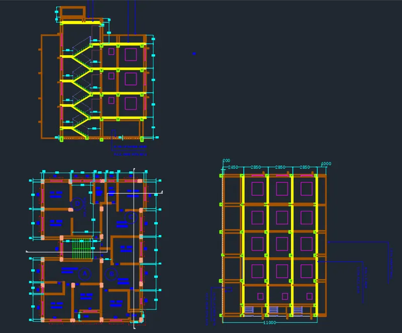
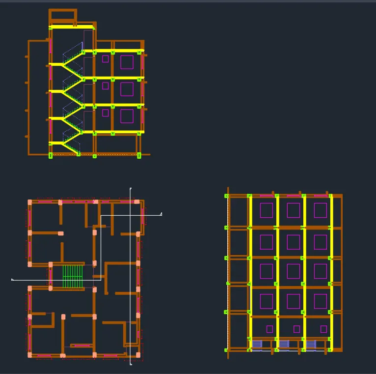
Aim :- To create the floor plan and sections A-A and B-B as given in the figure using AutoCAD.
Introduction :-
- The assumed dimensions of doors and windows are :-
- Main Door(D) = 1000mm X 2200mm
- Door 1(D1) = 700mm X 2000mm
- Door 2(D2) = 900mm X 2000mm
- Window 1(W1) = 1000mm X 1400mm
- Window 2(W2) = 1300mm X 1400mm
- Window 3(W3) = 1500mm X 1400mm
- Window 4(W4) = 600mm X 700mm
Procedure :-
- Open new file in AutoCAD and Type 'un' in command box and press enter.
- Change unit type to decimal and precision to 0.00 and insertion scale to millimeters.
Step 1 :- Creating Floors plan
- Type "XL" in command box and press enter.
- Click on "hor" in command box and select any point on the screen.
- Type "XL" in command box and press enter.
- Click on "ver" in command box and select any point on the horizontal xline.
- Type "O" for offset in command box and press enter.
- Specify offset distance as 250 and press enter.
- Select horizontal xline and click on bottom.
- Select vertical xline and click on right.
- Type "O" for offset in command box and press enter.
- Specify offset distance as 3100 and press enter.
- Select the vertical offsetted xline of wall thickness and click on right.
- Type "O" for offset in command box and press enter.
- Specify offset distance as 125 and press enter.
- Select last offset line to give wall thickness and click on right.
- Type "O" for offset in command box and press enter.
- Specify offset distance as 2550 and press enter.
- Select the last vertical offset line and click on right.
- Type "O" for offset in command box and press enter.
- Specify offset distance as 125 and press enter.
- Select last offset to give wall thickness and click on right.
- Type "O" for offset in command box and press enter.
- Specify offset distance as 1250 and press enter.
- Select the last vertical offset line and click on right.
- Type "O" for offset in command box and press enter.
- Specify offset distance as 125 and press enter.
- Select last offset to give wall thickness and click on right.
- Type "O" for offset in command box and press enter.
- Specify offset distance as 1250 and press enter.
- Select the last vertical offset line and click on right.
- Type "O" for offset in command box and press enter.
- Specify offset distance as 125 and press enter.
- Select last offset to give wall thickness and click on right.
- Type "O" for offset in command box and press enter.
- Specify offset distance as 3000 and press enter.
- Select the last vertical offset line and click on right.
- Type "O" for offset in command box and press enter.
- Specify offset distance as 250 and press enter.
- Select last offset line to give wall thickness and click on right.
- Type "TR" in command box for Trim command and trim the outer portions and extra lines.
- Type "O" for offset in command box and press enter.
- Specify offset distance as 3100 and press enter.
- Select the horizontal offset xline of wall thickness and click on bottom.
- Type "O" for offset in command box and press enter.
- Specify offset distance as 125 and press enter.
- Select horizontal offset xline to give wall thickness and click on bottom.
- Type "O" for offset in command box and press enter.
- Specify offset distance as 3200 and press enter.
- Select the last offset line of wall thickness and click on bottom.
- Type "O" for offset in command box and press enter.
- Specify offset distance as 250 and press enter.
- Select last offset line to give wall thickness and click on bottom.
- Type "L" for line command and Draw a line connecting the two bathrooms.
- Type "O" for offset in command box and press enter.
- Specify offset distance as 2400 and press enter.
- Select the line drawn above of wall thickness and click on bottom.
- Type "O" for offset in command box and press enter.
- Specify offset distance as 125 and press enter.
- Select last offset line to give wall thickness and click on bottom.
- Type "O" for offset in command box and press enter.
- Specify offset distance as 3775 and press enter.
- Select the last offset line of wall thickness and click on bottom.
- Type "O" for offset in command box and press enter.
- Specify offset distance as 250 and press enter.
- Select the last offset line and give wall thickness and click on bottom.
- Type "EX" for extend line command in the command box and extend the last 2 offset lines to left wall edge.
- Type "O" for offset in command box and press enter.
- Specify offset distance as 3225 and press enter.
- Select the line drawn earlier and click on bottom.
- Type "O" for offset in command box and press enter.
- Specify offset distance as 125 and press enter.
- Select the last offset line and click on bottom.
- Type "O" for offset in command box and press enter.
- Specify offset distance as 2950 and press enter.
- Select the last offset line and click on bottom.
- Type "O" for offset in command box and press enter.
- Specify offset distance as 4475 and press enter.
- Select the left edge of the living room in flat C and click on right.
- Adjust the right wall of flat C living room as shown in question.
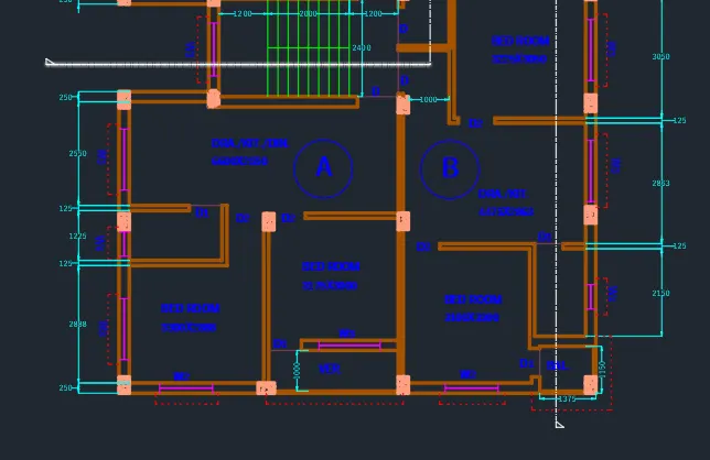
Step 2 :- Creating stairs and flat A and flat B
- Type "O" for offset in command box and press enter.
- Specify offset distance as 2400 and press enter.
- Select the bottom outer wall edge of flat D and click on bottom
- Type "O" for offset in command box and press enter.
- Specify offset distance as 250 and press enter.
- Select the last offset line and click on bottom
- Type "L" for line command and draw lines connecting the edges of columns.
- Type "L" for line command and draw a line at the left edge of stair way.
- Type "O" for offset in command box and press enter.
- Specify offset distance as 1200 and press enter.
- Select the line drawn earlier and click on left.
- Type "O" for offset in command box and press enter.
- Specify offset distance as 2000 and press enter.
- Select the line drawn earlier and click on left.
- Type "O" for offset in command box and press enter.
- Specify offset distance as 250 and press enter.
- Select the last offset line and click on right.
- Select the last offset line and click on right.
- Select the last offset line and click on right.
- Select the last offset line and click on right.
- Select the last offset line and click on right.
- Select the last offset line and click on right.
- Select the last offset line and click on right.
- Select the last offset line and click on right.
- Type "L" for line command and draw line connecting mid points of the stairs.
- Type "L" for line command and draw left wall with reference of stairs.
Step 3 :- Creating flat A and flat B
- Type "L" for line command and draw the top wall of flat B starting from the middle of stairway.
- Type "O" for offset in command box and press enter.
- Specify offset distance as 125 and press enter.
- Select top wall of the bedroom of flat B and click at bottom.
- Type "O" for offset in command box and press enter.
- Specify offset distance as 3050 and press enter.
- Select the last offset line at top and click on bottom.
- Type "O" for offset in command box and press enter.
- Specify offset distance as 125 and press enter.
- Select the last offset line and click on bottom.
- Type "O" for offset in command box and press enter.
- Specify offset distance as 2863 and press enter.
- Select the last offset line and click on bottom.
- Type "O" for offset in command box and press enter.
- Specify offset distance as 125 and press enter.
- Select the last offset line and click on bottom.
- Type "L" for line command and draw a line at the right wall edge of top bed room of flat B on vertical xline
- Type "O" for offset in command box and press enter.
- Specify offset distance as 3225 and press enter.
- Select the line drawn earlier at right wall and click on left.
- Type "O" for offset in command box and press enter.
- Specify offset distance as 125 and press enter.
- Select the last offset line and click on left.
- Type "O" for offset in command box and press enter.
- Specify offset distance as 2563 and press enter.
- Select the bottom edge of stair way and click on bottom.
- Type "O" for offset in command box and press enter.
- Specify offset distance as 125 and press enter.
- Select the last offset line and click on bottom.
- Type "O" for offset in command box and press enter.
- Specify offset distance as 3000 and press enter.
- Select the bottom edge of stair way and click on bottom.
- Type "O" for offset in command box and press enter.
- Specify offset distance as 250 and press enter.
- Select the last offset line and click on bottom.
- Type "O" for offset in command box and press enter.
- Specify offset distance as 2550 and press enter.
- Select the bottom edge of wall left of stairway and click on bottom.
- Type "O" for offset in command box and press enter.
- Specify offset distance as 125 and press enter.
- Select the last offset line and click on bottom.
- Type "TR" in command box for Trim command and trim the extra portions.
- Type "O" for offset in command box and press enter.
- Specify offset distance as 1225 and press enter.
- Select the last offset line and click on bottom.
- Type "O" for offset in command box and press enter.
- Specify offset distance as 125 and press enter.
- Select the last offset line and click on bottom.
- Type "O" for offset in command box and press enter.
- Specify offset distance as 2888 and press enter.
- Select the last offset line and click on bottom.
- Type "O" for offset in command box and press enter.
- Specify offset distance as 250 and press enter.
- Select the last offset line and click on bottom.
- Type "TR" in command box for Trim command and trim the extra portions of xlines drawn at different points.
- Type "L" in command box for line command and press enter.
- Draw line at the left inner wall edge of flat A.
- Type "O" for offset in command box and press enter.
- Specify offset distance as 2275 and press enter.
- Select the line drawn earlier and click on right.
- Type "O" for offset in command box and press enter.
- Specify offset distance as 125 and press enter.
- Select the last offset line and click on right.
- Type "O" for offset in command box and press enter.
- Specify offset distance as 3300 and press enter.
- Select the line drawn earlier and click on right.
- Type "O" for offset in command box and press enter.
- Specify offset distance as 125 and press enter.
- Select the last offset line and click on right.
- Type "TR" in command box for Trim command and trim the extra portions.
- Type "O" for offset in command box and press enter.
- Specify offset distance as 1250 and press enter.
- Select the line drawn earlier and click on left.
- Type "O" for offset in command box and press enter.
- Specify offset distance as 125 and press enter.
- Select the last offset line and click on left.
- Type "L" in command box for line command and press enter.
- Draw line at the top edge of bathroom above.
- Type "O" for offset in command box and press enter.
- Specify offset distance as 2150 and press enter.
- Select the line drawn earlier and click on left.
- Type "O" for offset in command box and press enter.
- Specify offset distance as 250 and press enter.
- Select the last offset line and click on left.
- Type "L" in command box for line command and press enter.
- Draw balcony using line command.
- Type "TR" in command box for Trim command and trim the extra portions.
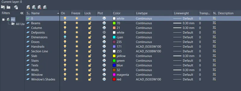
Step 4 :- Creating Layers
- Type "LA" in the command box and press enter.
- In Layer properties manager, create new layers by clicking on new layer icon.
- Define different layers and assign colours and line type to them as follow :-
Step 5 :- Creating Doors and Windows
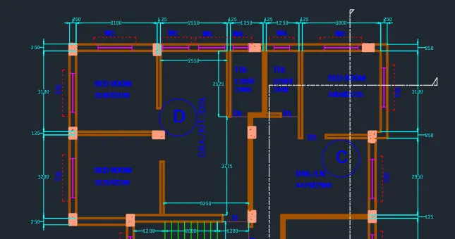
Creating Doors :-
- Create the door openings as per the dimensions assumed and Assign layers accordingly.
- Type "L" in command box for line command and press enter.
- Using line command, draw a line across the wall where door openings are created.
- Door Lines are created as per dimension assumed earlier of 700(for D1), 900(for D2), 1000(for D).
Creating Windows :-
- Create window openings as per dimensions assumed and Assign layers accordingly.
- Type "L" in command box for line command and press enter.
- Using line command, draw a line across the wall Offset the line through a distance of 1000(for W1), 1300(for W2), 1500(for W3), 600(for W4).
- Using line command, draw two lines connecting the above drawn lines at the middle.
- All windows are created with same procedure and position is specified in the question figure.
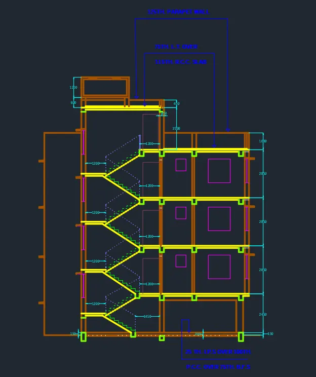
Step 6 :- Creating Section View A-A
- Type "XL" in command box and press enter.
- Click on "ver" in command box.
- Select the points required to take the projection for Section A-A.
- Draw a Horizontal line for Ground level which cuts all vertical line projections.
- Now, type "Breakpoint" in the command box and break all the vertical projection lines from the point of intersection with horizontal line.
- Type "E" for erase command and press enter.
- Select all the vertical line below the horizontal line and press enter.
- Type "O" for offset in command box and press enter.
- Specify offset distance as 150 and press enter.
- Select the horizontal line drawn earlier and click on top.
- Type "O" for offset in command box and press enter.
- Specify offset distance as 50 and press enter.
- Select the horizontal line drawn earlier and click on bottom.
- Type "O" for offset in command box and press enter.
- Specify offset distance as 25 and press enter.
- Select the top offset line and click on bottom.
- Type "O" for offset in command box and press enter.
- Specify offset distance as 100 and press enter.
- Select the top offset line and click on bottom.
- Type "O" for offset in command box and press enter.
- Specify offset distance as 2450 and press enter.
- Select the horizontal line drawn at the beginning and click on top.
- Type "O" for offset in command box and press enter.
- Specify offset distance as 2850 and press enter.
- Select the last offset line and click on top.
- Select the last offset line and click on top.
- Select the last offset line and click on top.
- Type "O" for offset in command box and press enter.
- Specify offset distance as 125 and press enter.
- Select each floors line and give the slab thickness offset in bottom.
- Type "TR" in command box for Trim command and trim the extra portions.
- Change the current layer to window layer.
- Type "L" in the command box and press enter.
- Draw a line connecting two window line projections at the first-floor level.
- Type "O" for offset in command box and press enter.
- Specify offset distance as 800 and press enter.
- Select the last line drawn and click on top.
- Type "rec" in the command box and press enter.
- Draw a window with 1300X1400 as per W2 dimensions.
- Again draw a window with 600X700 as per W4 dimensions.
- Copy the rectangles to all the floors as shown in question figure.
- Type "TR" in command box for Trim command and trim the extra portions.
- Change the layer to stairs.
- Draw an offset point of 1450mm from the right edge of stair way for the ground floor stairs.
- Draw an offset point of 1200mm from the left edge of stair way for the ground floor stairs.
- Type "L" in command box and press enter.
- Turn on OSNAPS and Ortho Mode.
- Specify first point and click on the bottom point of the offset line drawn at 1450 from the right edge.
- Specify next point : Keep curser to top and type 143.75 and press enter.
- Specify next point : Keep curser to left and type 250 and press enter.
- Repeat the steps till the floor reaches.
- For the rest floors specify riser height as 158.33.
- Repeat the same process until landing is reached Drawn land slab.
- Type "rec" in the command box and press enter.
- Draw door of flat "D" at each floor entrance as shown in the question figure above.
- Type "O" for offset in command box and press enter.
- Specify offset distance as 75 and press enter.
- Select the top edge and click on top.
- Type "O" for offset in command box and press enter.
- Specify offset distance as 1000 and press enter.
- Select the top edge and click on top.
- Type "O" for offset in command box and press enter.
- Specify offset distance as 2500 and press enter.
- Select the top edge and click on top.
- Type "O" for offset in command box and press enter.
- Specify offset distance as 450 and press enter.
- Select the last offset line and click on top.
- Type "TR" in command box for Trim command and trim the extra portions.
- Type "rec" in the command box and press enter.
- Draw the top tank using rectangle command.
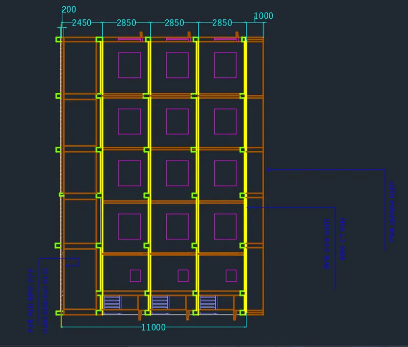
Step 7 :- Creating Section View B-B
- Type "XL" in command box and press enter.
- Click on "Hor" in command box.
- Select the points required to take the projection for Section B-B.
- Draw a Vertical line for Ground level which cuts all horizontal line projections.
- Now, type "Breakpoint" in the command box and break all the vertical projection lines from the point of intersection with horizontal line.
- Type "E" for erase command and press enter.
- Select all the vertical line below the horizontal line and press enter.
- Type "O" for offset in command box and press enter.
- Specify offset distance as 200, 2450, 2850, 2850, 2850, 1000.
- Type "O" for offset in command box and press enter.
- Specify offset distance as 115 and give the slab thickness.
- Use trim command to trim extra portions of drawing.
- Draw the windows(W3 and W4) and use copy command to paste it in desire locations.
- Specify the obects to different created layers.
- Give dimensions and Create Text in the drawing.
Result :-
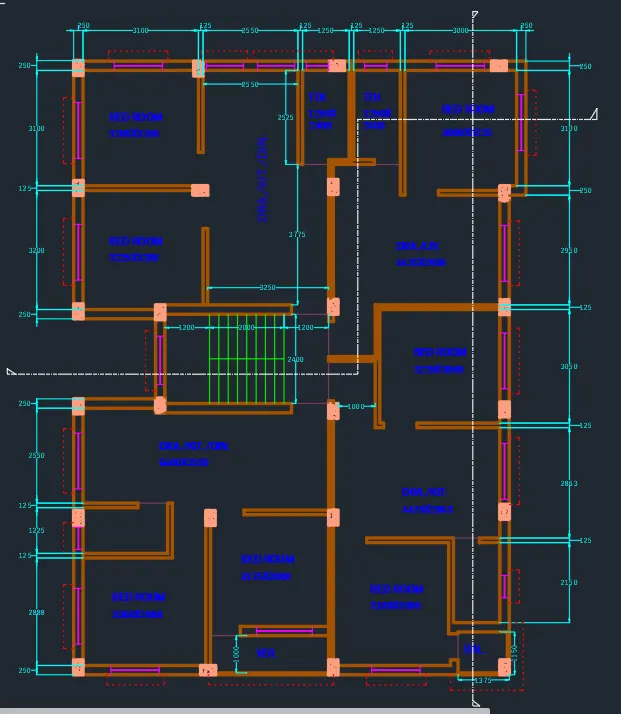
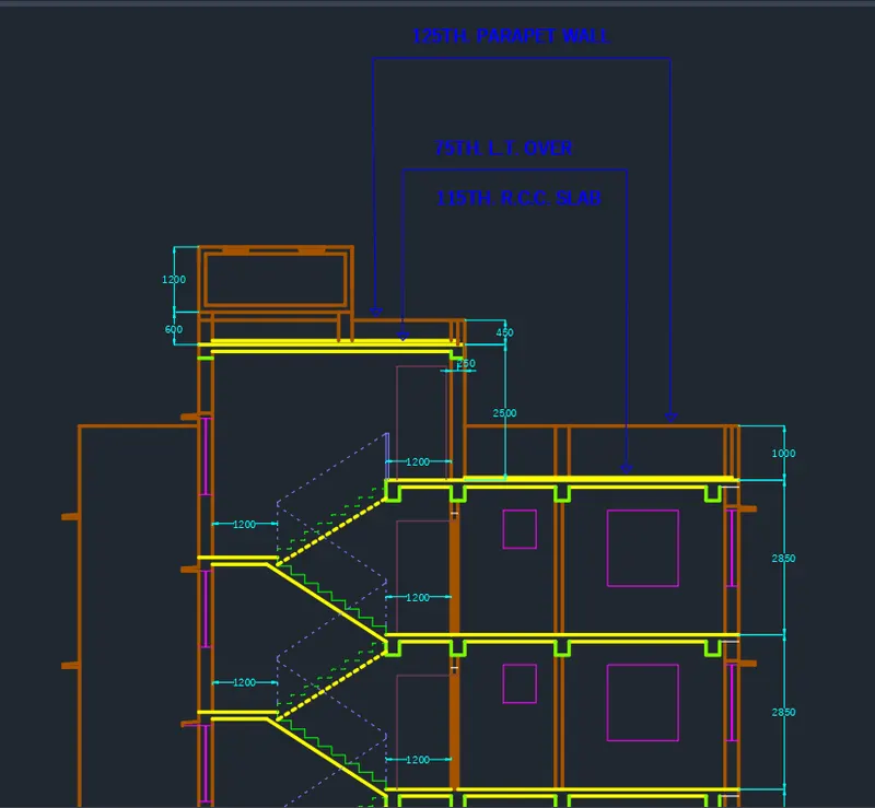
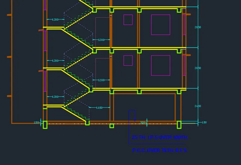
- The Floor plan of 1st,2nd and 3rd floors with two section views from front side are drawn using AutoCAD.
- In the first step flat C and flat D are made as per given dimensions from the plan.
- Then flat A and flat B are made as per given dimensions from the plan.
- Then stairs are made.
- where thread size is Taken as 250 and riser as 143.75 for ground floor and 158.33 for rest of the floors.
- Then Layer is created and the property and name is provided to each layer and the obejects created are assigned to the respected layers.
- The dimensions and text are added according to plan after creating flats A, B, C and D.
- Section views are drawn from projection lines from the plan view.
- The result provided consists of pics dividing each drawing.
FLOOR PLAN :-
Section A-A :-
Section B-B :-