Modelling of 25 storey building with the specified properties using ETABS
AIM :-
- To model a 25 storey building on ETABS with given structural properties.
- To check if the translational fundamental natural period of vibration in both the x and y direction is approximate, Tx1 = 4.4 seconds Ty1 = 4.2 seconds.
- To check if the provision in Table 5 of IS 1893 (part 1) – 2016, on torsional irregularity is satisfied.
- To check if the two provisions of clause 7 in Table 6 (shown below) of IS 1893 (part 1) – 2016, regarding vertical irregularity is satisfied.
- To check if provision on inter-storey drift limitations in clause 7.11.1.1 is satisfied.
GIVEN :-
- Ground floor or plinth floor level is at a height of 1.5 metres from the base.
- Each of the successive 25 storeys has a storey height of 3 metres.
- Buildings are assumed to be pinned at the base.
- All columns in all storeys are of the same size.
- All beams in all storeys are of the same size.
- The building is located on Soil type-II and in Zone-III.
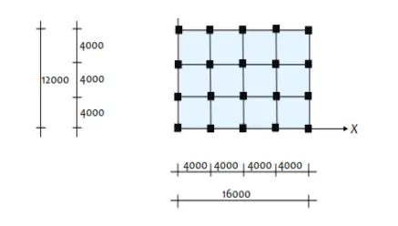
Structural Element Sizes :-
- Beams : 300 × 400 mm
- Columns : 800 × 800 mm
- Slab : 150 mm thick
Material Properties :-
- Grade of Concrete : M30
- Grade of Steel Reinforcement Bars : Fe 415
Loads :-
- Dead Load on beams from infill wall = 10 kN/m (Assume the same for roof floor in view of parapet)
- Live load on floor = 3 kN/m2 (Assume the same for roof floor)
PROCEDURE :-
Step 1 :-
- Open the ETAB software and click on "New Model".
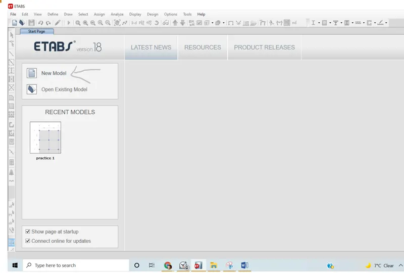
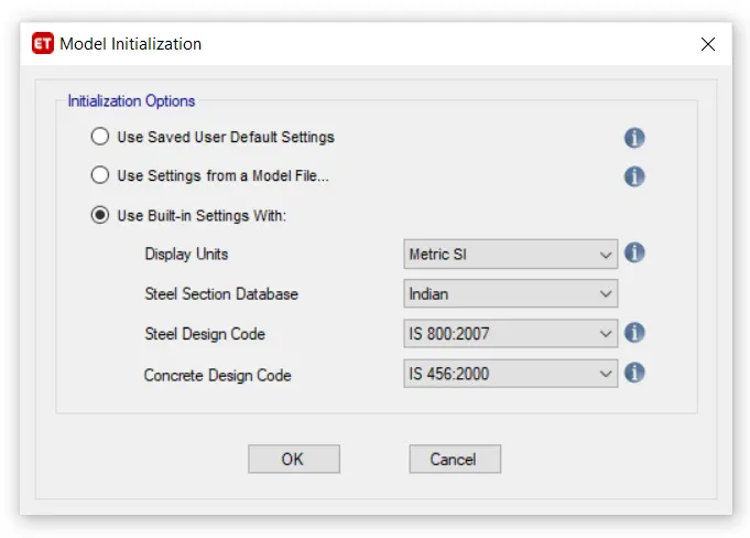
- "Model initialization" dialogue box will open.
- Go to the "built-in settings with" option and change the different options as "Select Display unit > Metric SI", "Steel section database > Indian", "Steel design code > IS 800:2007", "Concrete design code > IS 456:2000"
Step 2 :- Creating grids and storeys
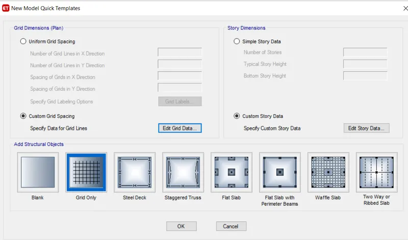
- "New Model Quick Template" dialogue box will open.
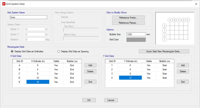
- Check the "Custom Grid Spacing" and click on "Edit Grid data".
- The "Grid System Data" dialogue box will open.
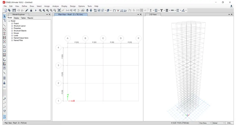
- Check on the "Display grid data as ordinates" option and provide the grid's data as given in the question and then click "OK".
- Now check the "Custom Story Data" and click on "Edit Story data".
- The "Story Data" dialogue box will open.
- Click on Story 1and rename it as "Plinth Level" and give plinth level height as 1.5m.
- Click on Story 2 and rename it as "Storey 1" and give storey height as 3m.
- Again click Story 3 and rename it as "Storey 2" and give storey height as 3m.
- Again click Story 4 and rename it as "Storey 3" and give storey height as 3m.
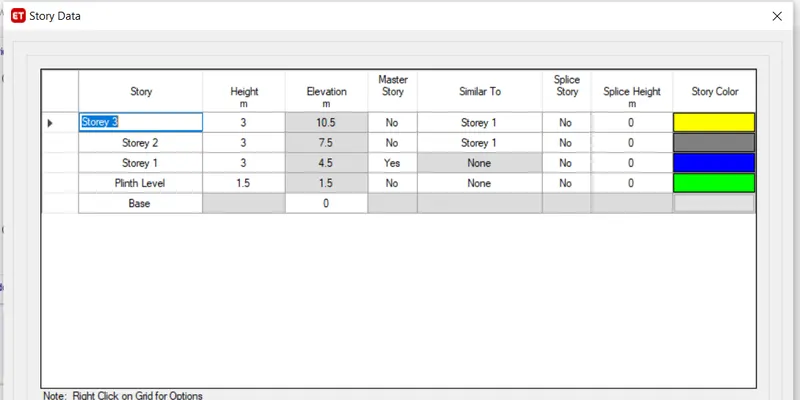
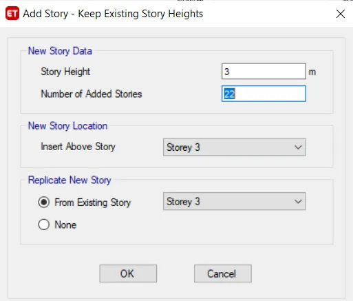
- Now Right-click in the window and select "add story" and Select "Keep Existing Story Height".
- The "Add Story" dialogue box will open.
- Fill in the required data as per the question requirements.
- Click "OK" and rename all other storeys.
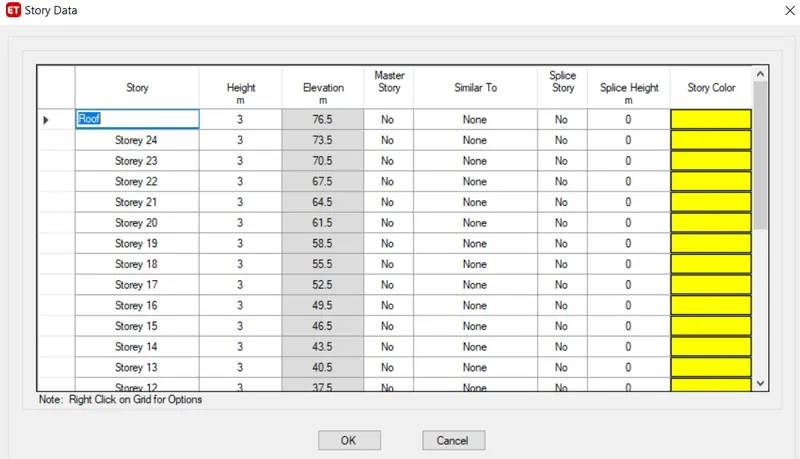
- The following result will shown :-
Step 3 :- Adding Materials
- Close all viewports and select Plan view and on "Storey 1" viewport on the window.
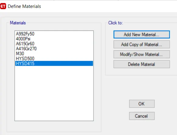
- To select the material, Go to the "define" tab and Select "Material Properties".
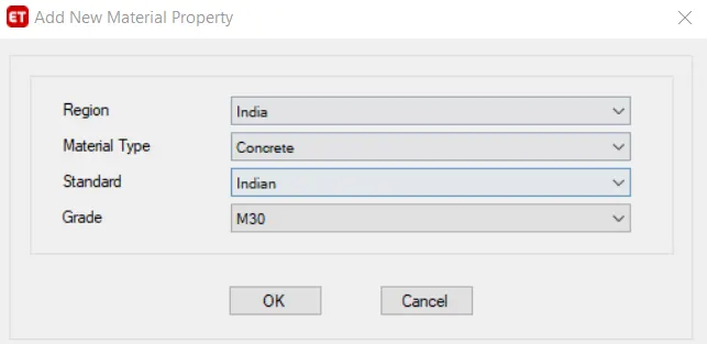
- Click on "Add new material". Select Region as "India", Material Type as "Concrete", Standard as "Indian" and Grade as "M30" and then click "OK".
- The "Material Property Data" dialogue box will open.
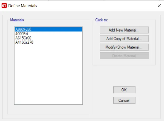
- Check the Data as per requirement or modify it accordingly.
- Click "Modify Material Property Design Data" and Select "Lightweight concrete".
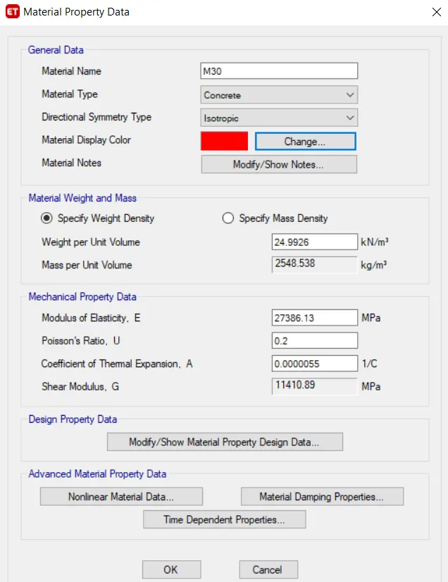
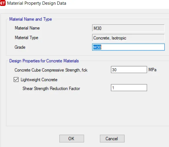
- Click "OK". The concrete material is added.
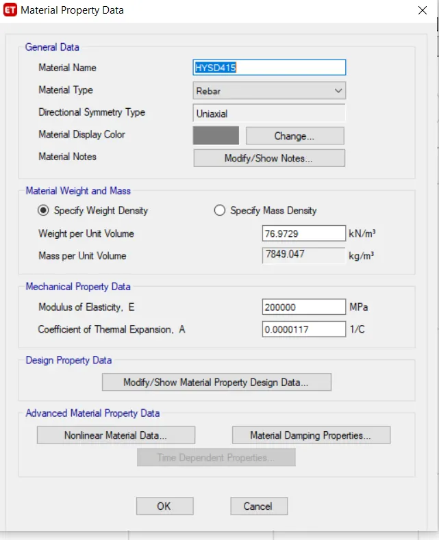
- Again go to add material and add the rebar for longitudinal reinforcement.
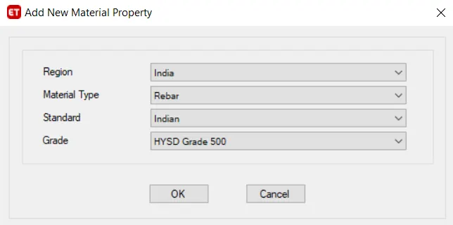
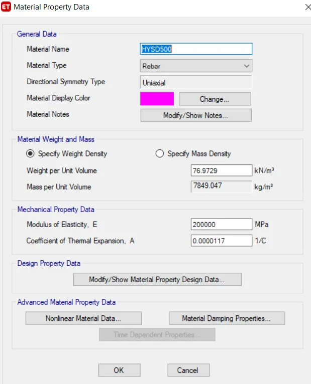
- Provide the data requirement and then click "OK".
- Similarly, add the shear reinforcement.
- Provide "grade 415" for shear reinforcement.
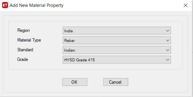
- Click "OK".
Step 4 :- Adding Columns, Beams and Slabs
- For beam, Go to the "Define" tab and Select "Section properties Select" and then click on "Frame sections".
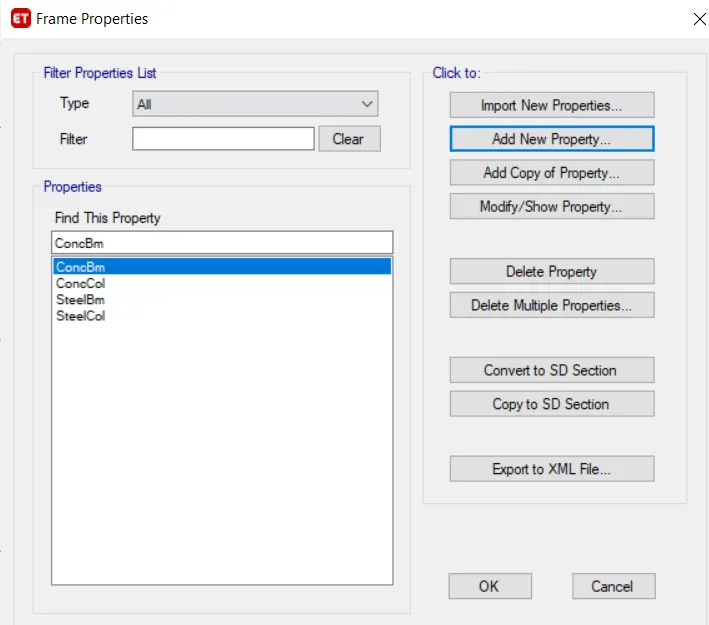
- Click on "Add New Property".
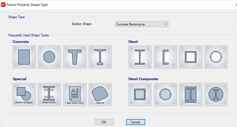
- Select "Rectangular concrete".
- Change Property name to "B-300 X 400"
- Provide Material "M30" and give dimensions as "Depth = 400" and "Width = 300".
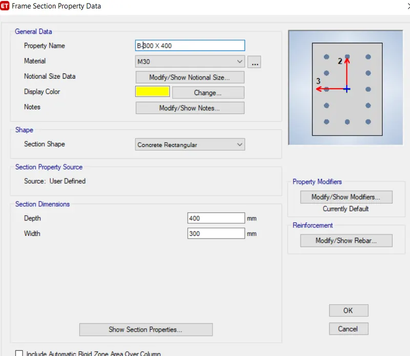
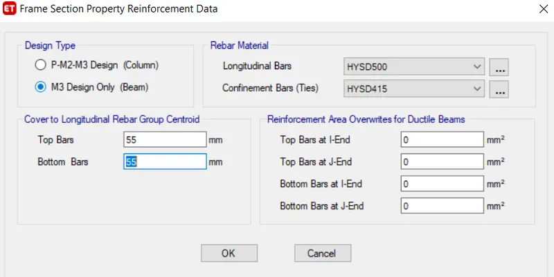
- Select "Modify rebar" and fill in the data as per requirement.
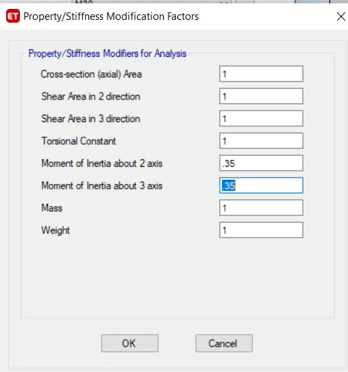
- Go to properties modifier and change the "MOI about the axes to 0.35" as per IS 1893 ( Part1): 2016 clause no 6.4.3.1.
- Click "OK" and the beam is added.
- Now, add another element "Column" by Clicking on "Add new property".
- Select "Rectangular concrete", Rename Property name as "C-800 X 800", provide Material "M30" and give section dimension as "Depth = 800" and "Width = 800".
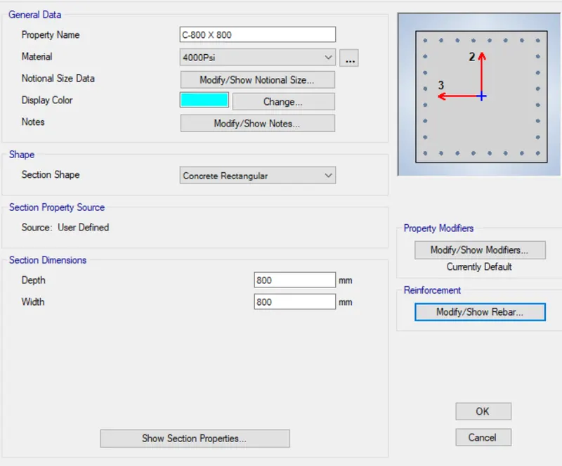
- Select "Modify rebar" and Fill in the data as per requirement.
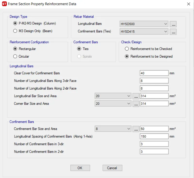
- Go to "Properties Modifier" and change the "MOI about the axes to 0.70" as per IS 1893 ( Part1): 2016 clause no 6.4.3.1.
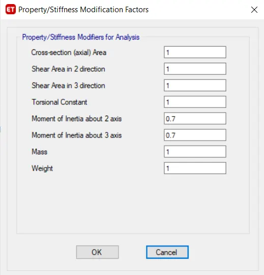
- Click "Ok" and the column is added.
- Now for Slab, Go to the "define" tab and Select "Section properties" then Select the "Slab section".
- Click on "Add New Property".
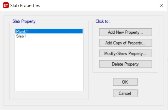
- Change Property name as "Slab 150", Slab material as "M30" and Modeling type as "Membrane" and provide the thickness of slab as 150mm.
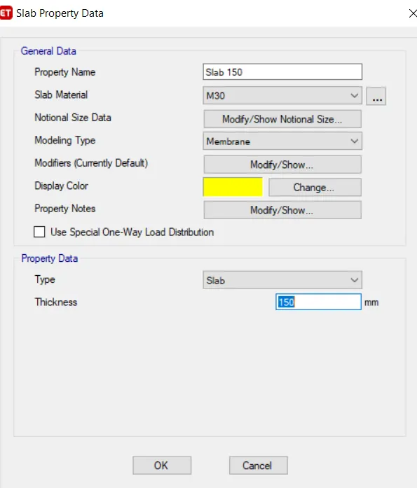
- Click "OK" and the Slab is added.
Step 5 :- Drawing Columns, Beams and Slabs
Drawing Columns :-
- Go to the Plan view of Story 1 and select the "All story" option at the bottom.
- Take the "Quick Draw Column" command and select the column "C-800 X 800".
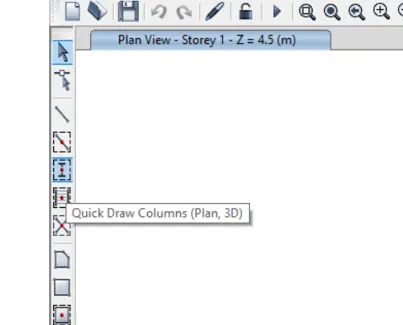
- Provide the columns, by clicking on all the intersection points of grids.
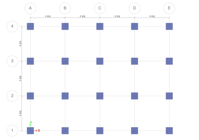
- Check the final result in the 3D view as well.
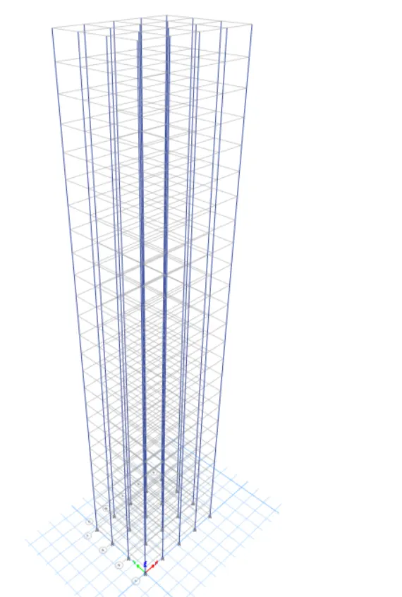
Drawing Beams :-
- Again open the first story plan view and select the "All story" option at the bottom.
- Go to the "Quick Draw Beam" command and Select Beam "B- 300 x 400".
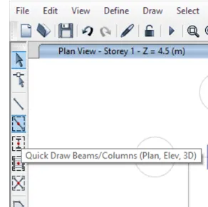
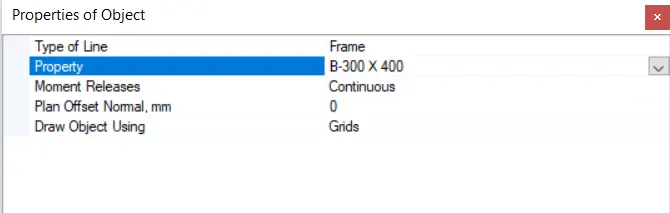
- Click on all grid lines in between columns to provide the beams.
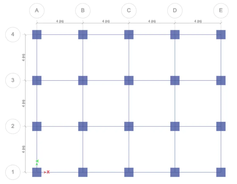
- Check the final result in the 3D view as well.
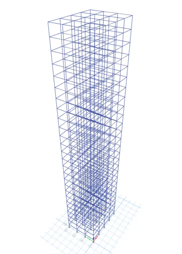
Drawing Slabs :-
- Again open the first story plan view and select the "Similar story" option at the bottom.
- Click on the "Quick Draw Floor" command and Select Slab "Slab 150".
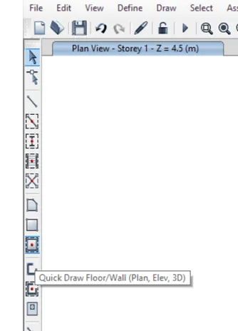
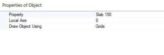
- Now click in between grids where the slab is to be provided.
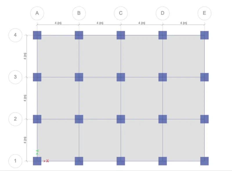
- Check the final result in the 3D view as well.
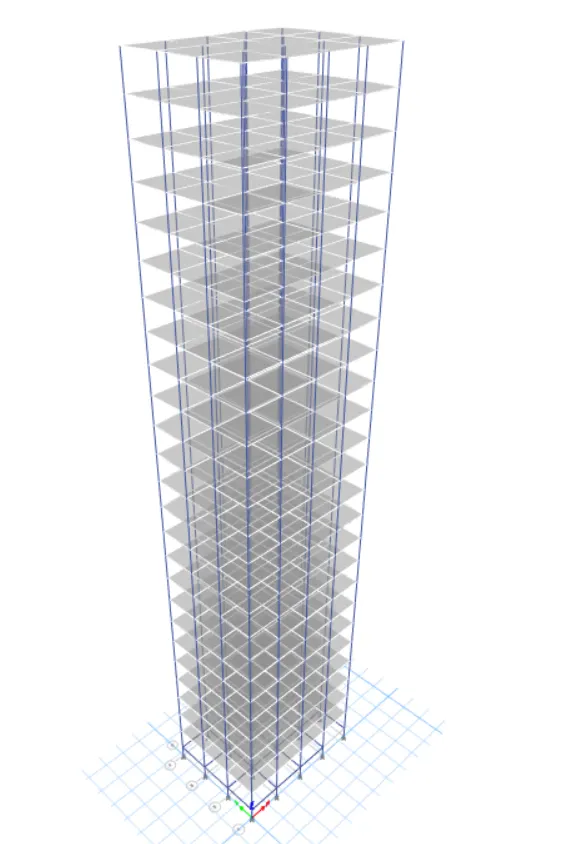
Step 6 :- Adding Support
- The building is assumed to be pinned at the base.
- For assigning pinned support, go to plan view and select "Base plan".
- Select the "One Story" option at the bottom.
- Select all the joints and then click on the "Assign" tab and Select "Joints" then Select "Restraints" and Select the base as "Pinned".
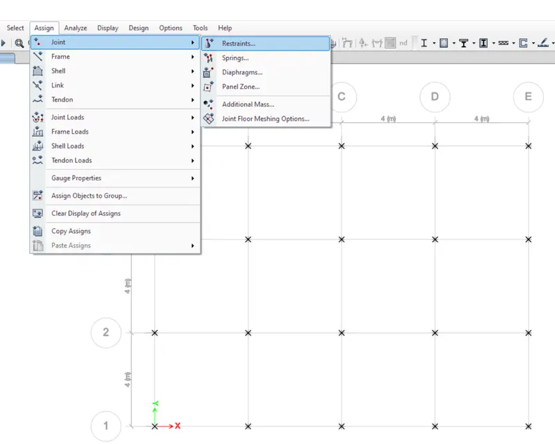
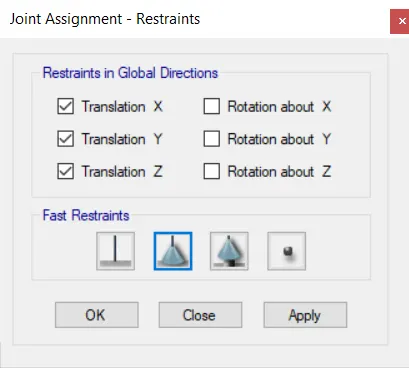
- Click "Apply" and then click "OK".
Step 7 :- Adding Load Pattern
- Click on the "Define" tab and select "Load patterns"
- Add different loads i.e., Dead load, Live load, Infill wall load, Earthquake load in both principal directions and Earthquake load with eccentricity in both principal directions.
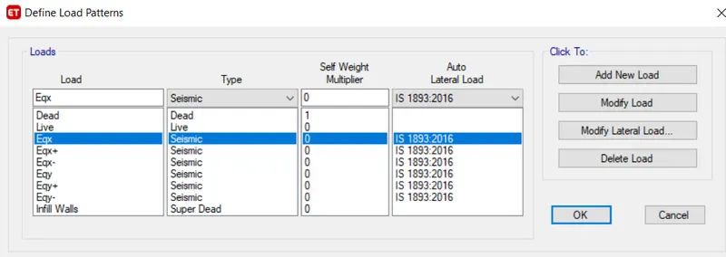
- Select "Eqx" load and click on "Modify Lateral Load".
- Fill in all the factors as per the conditions given in the question.
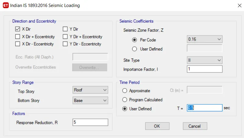
- Then click "OK".
- Now Select "Eqx+" load and click on "Modify Lateral Load".
- Provide Eccentric Ratio as "5%" and all other parameters are the same.
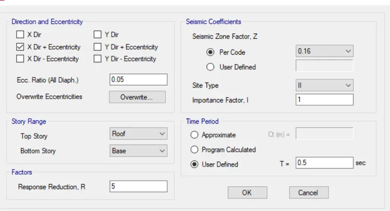
- Similarly, modify all the lateral load and click "OK".
Step 8 :- Assigning Loads to Structural Members
Assigning Live Load to Floors :-
- Open the "Storey 1" plan view and select the "Similar story" option at the bottom.
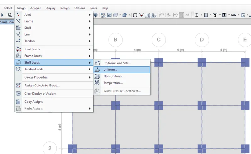
- Select all the shells and then go to the "Assign" tab, then select "Shell loads", and click on "Uniform".
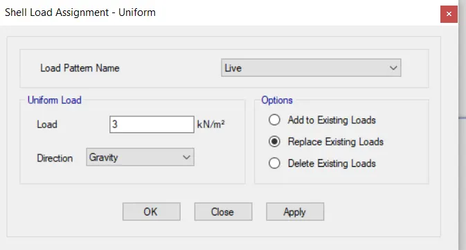
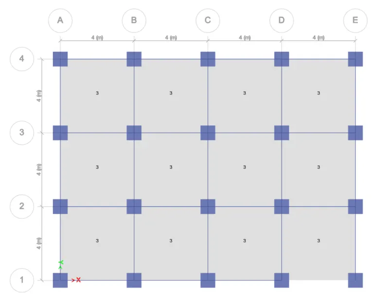
- Give the value of live load as per question requirement.
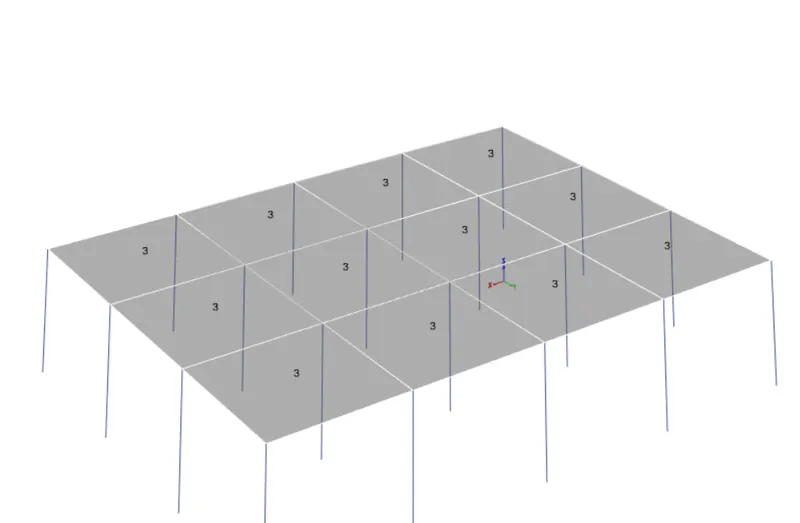
- Perspective view :-
Assigning Infill Walls Load to Beams :-
- Go to the "Select" tab and click on "Object type".
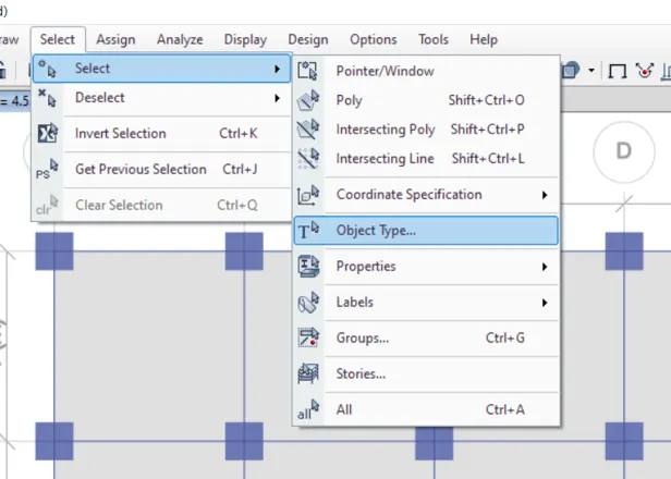
- Now Click on "Beams" and then click "Select"
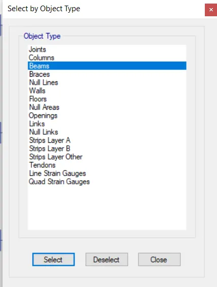
- All the beams are selected and for assurance check the bottom left corner.
- Now go to the "Assign" tab and select "Frame Loads" and then "Distributed".
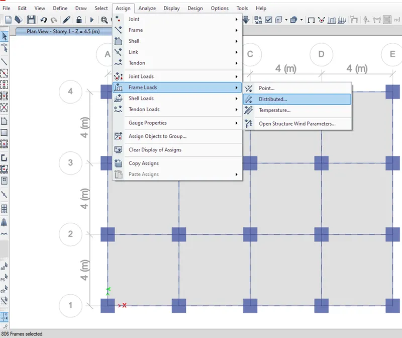
- Select "Infill Walls" as the load pattern name and give the value of "10 kN/m" in the uniform load section.
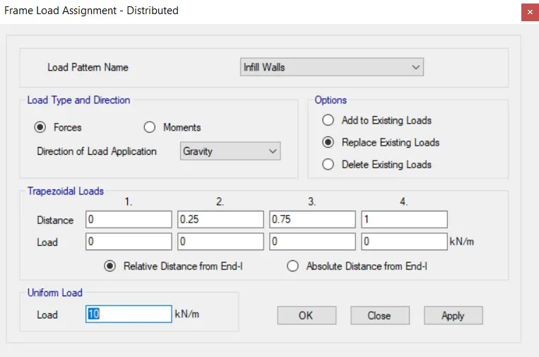
- Click "OK" and then click "Close".
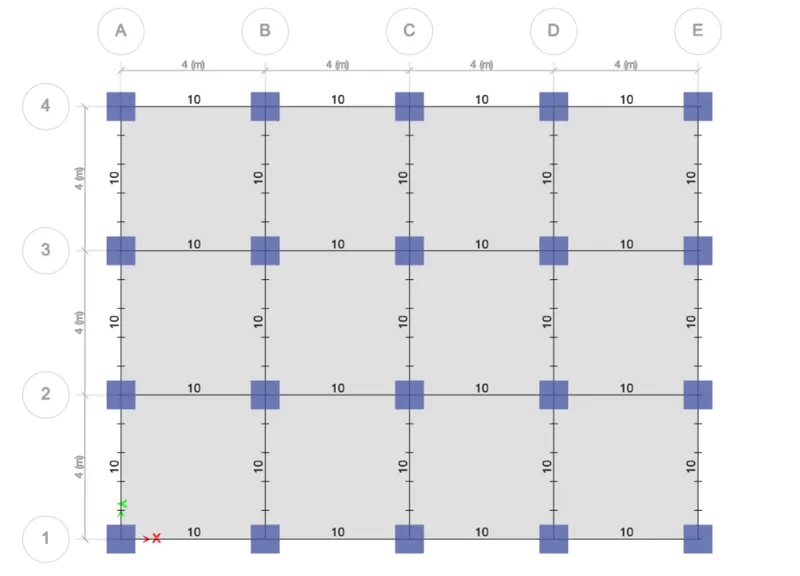
- Perspective view :-
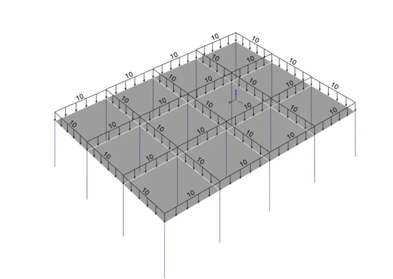
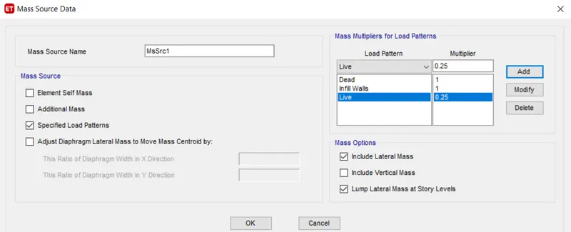
Step 9 :- Assigning the Mass Source
- Go to the "Define" tab and Select "Mass Source".
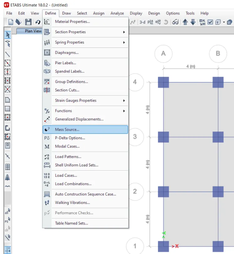
- Select the "Modify/Show mass source" option.
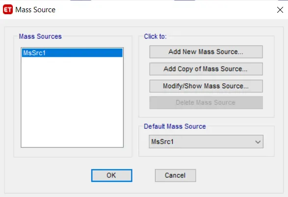
- Define the Seismic mass as per the code and then click "OK".
Step 10 :- Generating the Load combinations
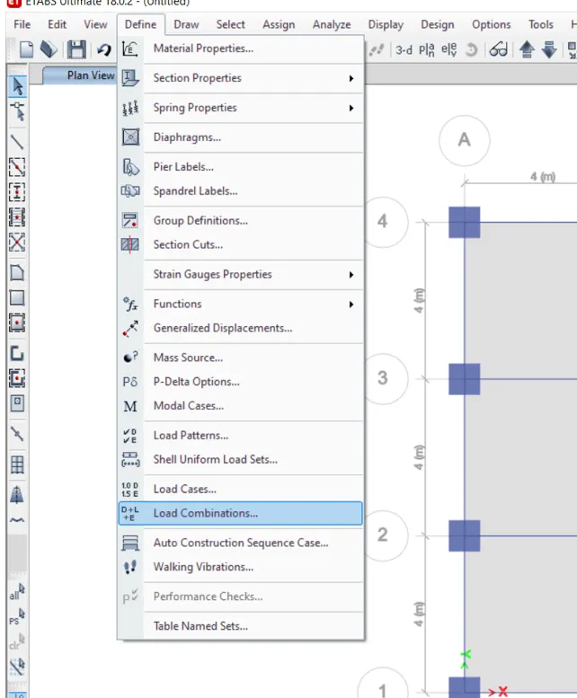
- Go to the "Define" tab and Select "Load Combination".
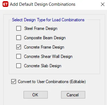
- Click on "Add Default Design Combos".
- Check the "Concrete Frame Design" and "Convert to User Combinations" box and then click "OK".
. 
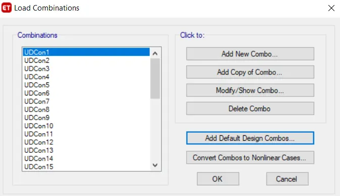
- The load combinations are generated. Click "OK".
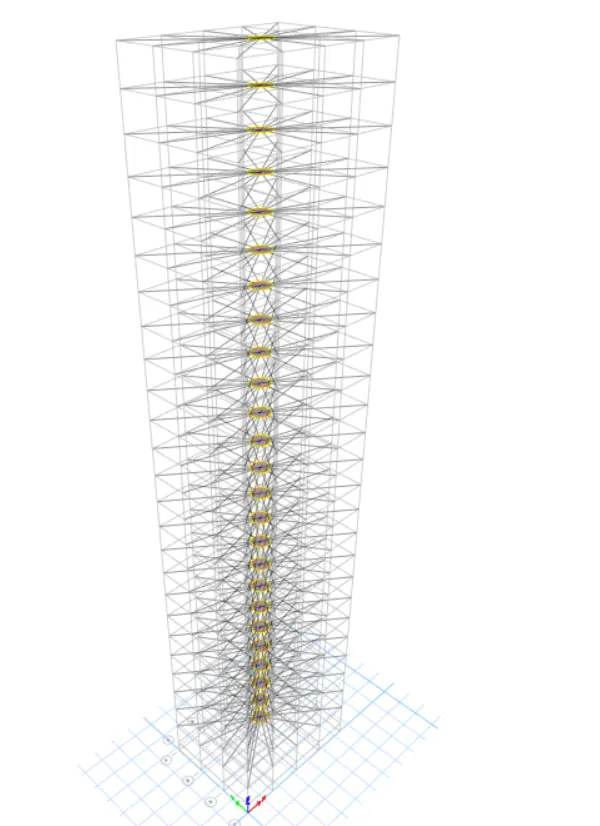
Step 11 :- Assigning the Diaphragm to the Floor
- Go to the "Select" tab and click on "Object type".
-
- Now Click on "Floors" and then click "Select" and then click on "Close".
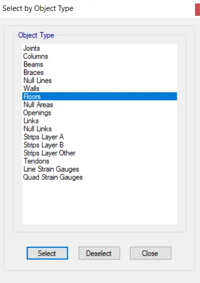
- Now go to the "Assign" tab Select "Shell" and then Click on "Diaphragm".
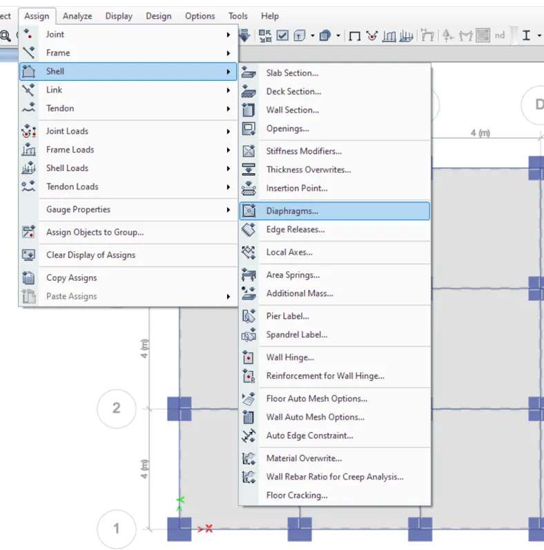
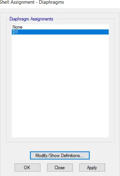
- "Shell Assignment - Diaphragm" dialogue box will open.
- Select "D1" and click on "Apply" and then click "OK". The diaphragms are applied.
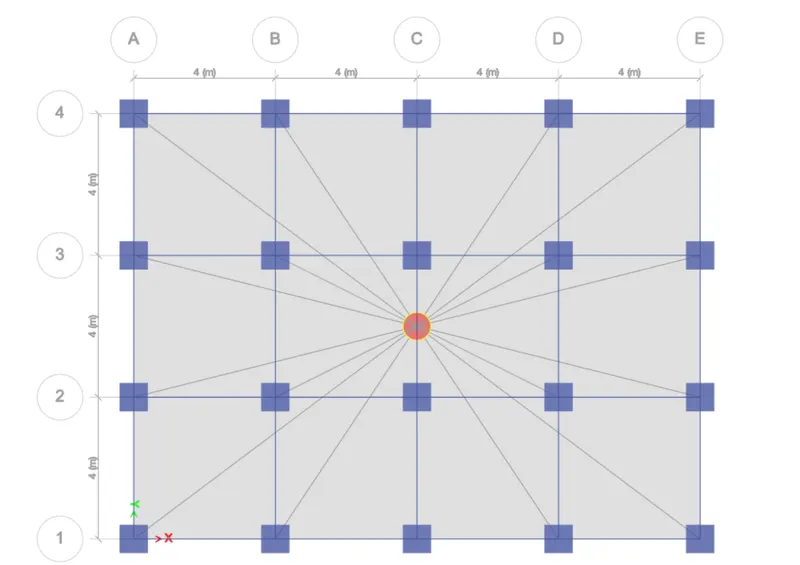
- Check the final result in the 3D view as well.
Step 12 :- Defining Modal Cases
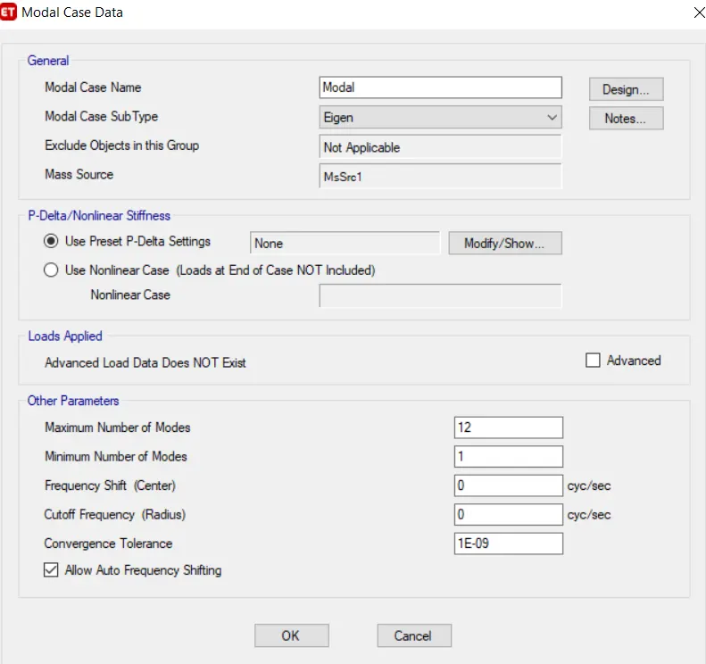
- Go to the "Define" tab and Click on "Modal Cases".
- Click on "Modify/Show Cases" and set the maximum number of modes as per choice.
Step 13 :- Checking Model
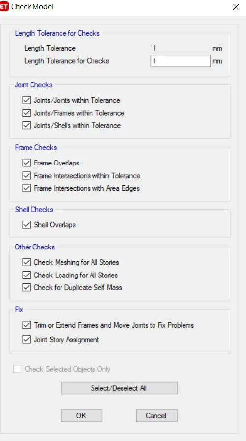
- Go to the "Analyze" tab and click on the "Check the Model" option.
- Select all the checks which are required to be checked and then click "OK".
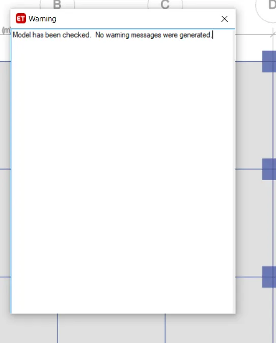
- If "No Warning" arise then the model is ready for analysis.
Step 14 :- Run Analysis
- After checking, click on the "Run Analysis" Icon or press the "F5" function key.
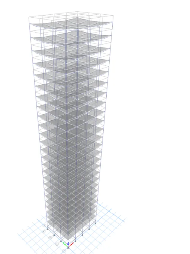
Step 15 :- Checking Deflection
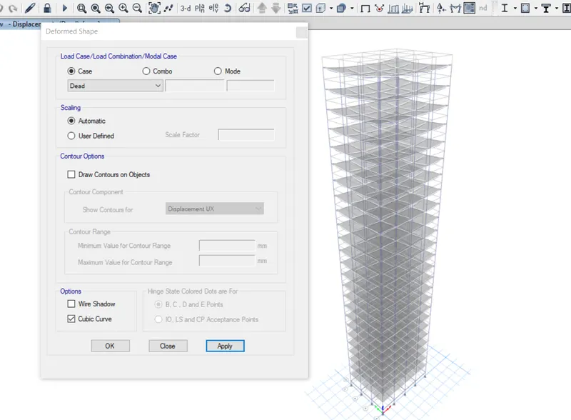
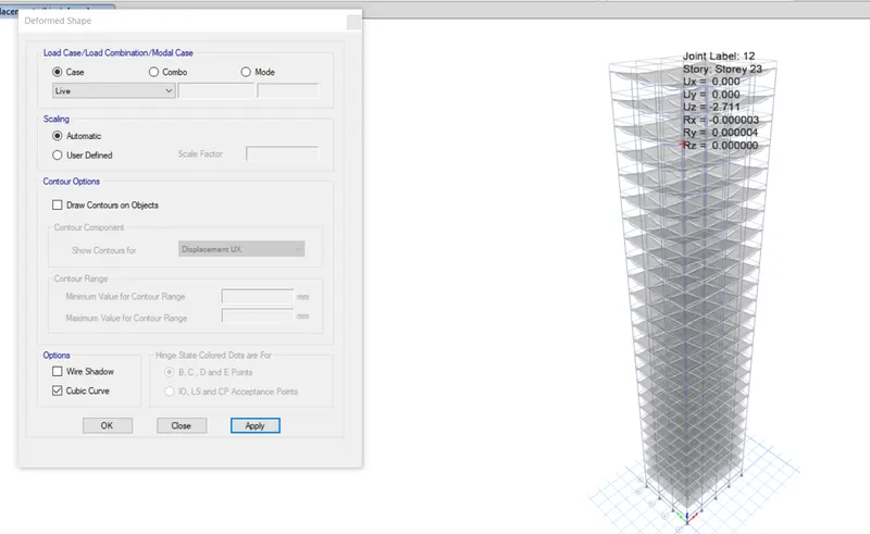
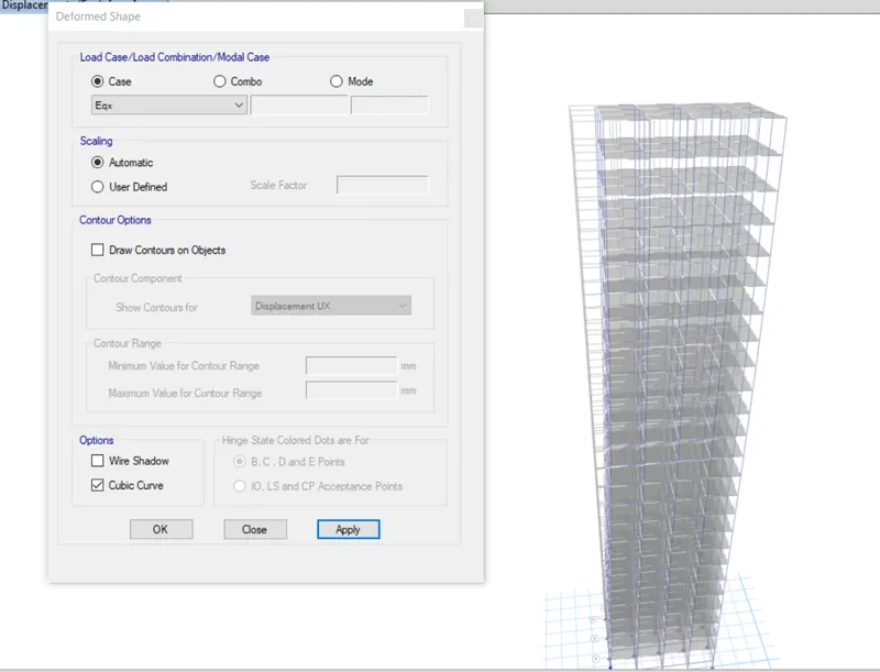
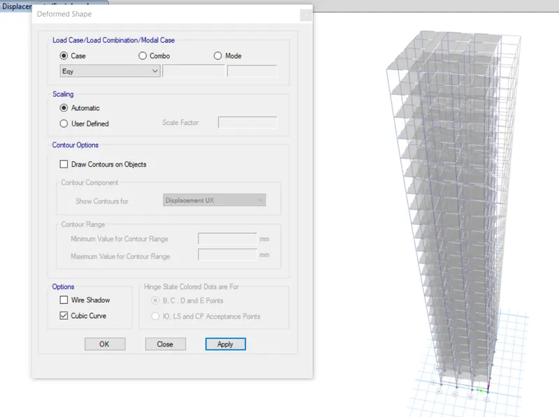
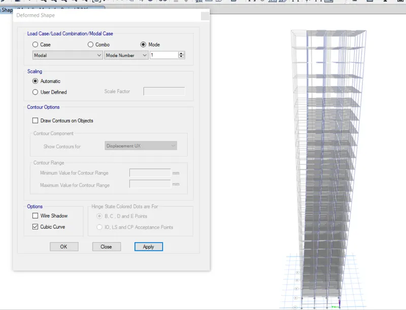
- Click on the "Show Deformed Shapes" icon or press the "F6" function key.
- The "Deformed Shape" dialogue box will open, select the load for which the deflection is required and then click on apply.
Step 16 :- Checking Base Reactions
- Go to the "Display" tab and select "Show Table".
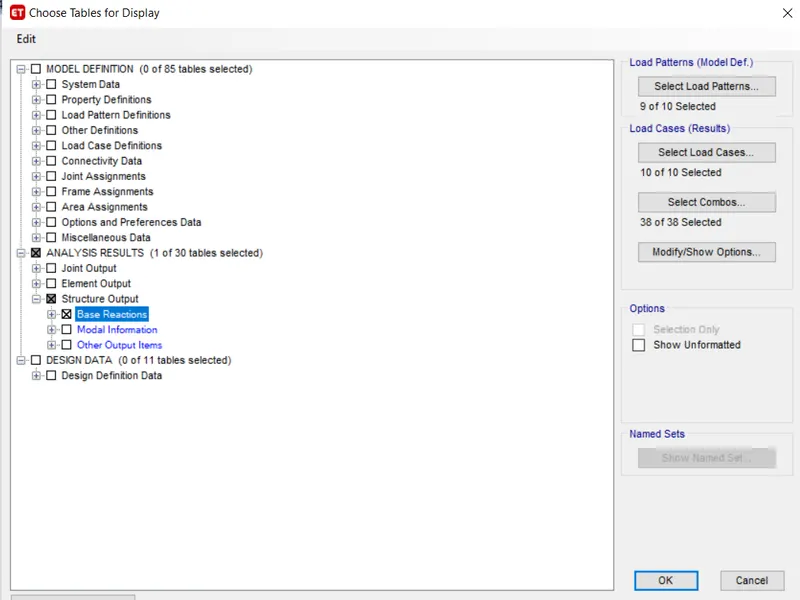
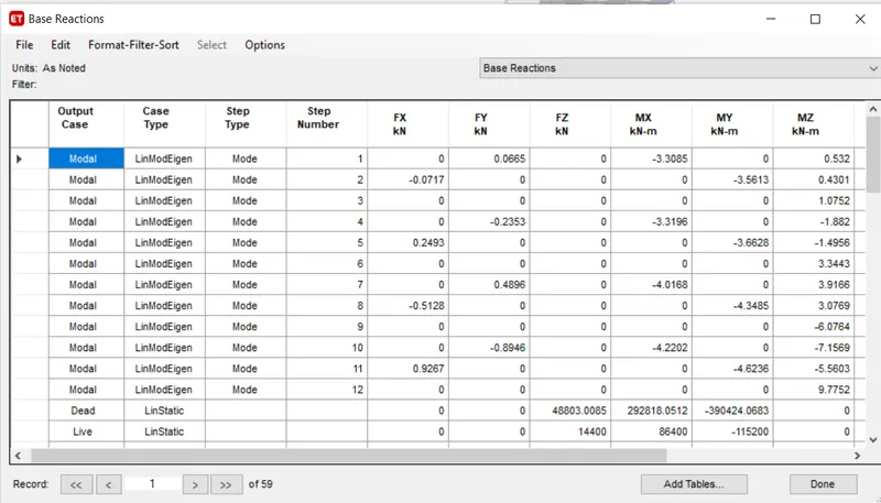
- Select the "Base Reaction" Table and then press "OK".
Step 17 :- Checking Modal Results
- Go to the "Display" tab and select "Show Table".
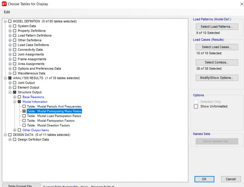
- Select the "Model Participating Mass Ratio" Table and then press "OK".
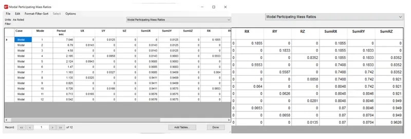
- From the table, the time periods,
Tx1 = 7.046 seconds and Ty1 = 6.79 seconds.
-
The mass participation ratios for first three modes are noted as follow :-
Tx1 = 0.8125
Tx2 = 0.1833
- By summing the three mode mass ratios, we are getting Tx1 + Tx2 = 0.995, which means the first two modes of seismic oscillation contribute more than 65% of building weight as per ETABS analysis. Thus, the code requirement is satisfied.
Storey Response Plot :-
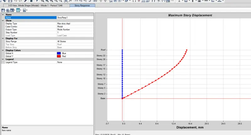
Modal Periods and Frequencies :-
- Go to the "Display" tab and select "Show Table".
- Select the "Modal periods and frequencies" Table and then press "OK".
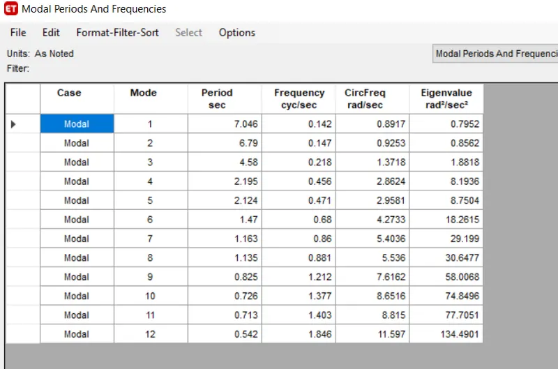
- From the table, the time periods,
Tx1 = 7.046 seconds and Ty1 = 6.79 seconds.
RESULT :-
- The 25-storey building has been modelled and analyzed on ETABS with the structural properties and load conditions provided in the questions.
- The requested data are verified as per Indian seismic standards.
- The time period separation of at least 10% is not achieved in the given practice.