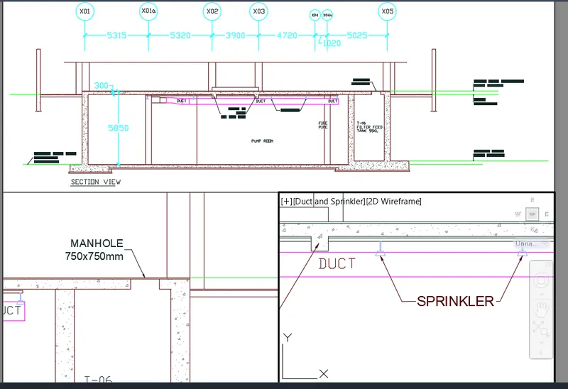
Creation of Multiple viewports, Scaling the drawing and setting in Template in AutoCad
Problem 1 :-
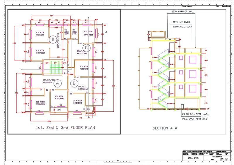
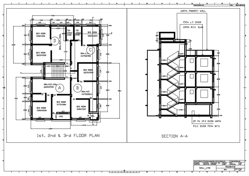
Aim :- To create a layout of the Plan and Section A-A of the Challenge of week 7, using the template Tutorial-mArch.dwt in a scale as given in the question figure using AutoCAD.
Introduction :-
1) Layout :-
- Layout viewports are objects that display views of model space.
- One can create, scale, and place viewport in paper space on a layout.
- On each layout, one can create one or more layout viewports.
- Each layout viewport is like a closed circuit TV monitor of a view of the model at a scale and orientation that user specify.
2) Plotting drawing :-
- Plot command is used to print the file or drawing in AutoCAD.
- Plots the view in the current viewport on the Model tab or the current view in the layout, depending on which tab you select to plot.
- Plots all of the objects in the current viewport, except objects on frozen layers. From a layout tab, all the geometry in paper space is plotted.
Procedure :-
- Open AutoCAD application.
- Type "Un" and press enter.
- Set Units to scale inserted content as "milimeter" and press Enter.
- Sets limits by typing "limits" in command box.
Step 1 :- Importing Drawing from Challenge of week 7
- Type xref in command box and press enter.
- Click on "Attachement".
- Keep scale as 1.
- Click on insertion point as specify on screen.
- Click on okay and specify the point of insertion.
- Right click on the W7Q1 drawing and select the bind option.
- In pop up click on insert the drawing into "W10Q1" along with layers.
Step 2 :- Creating Layout
- Go to layout tab and delete the current viewports available.
- Right click on the layout tab.
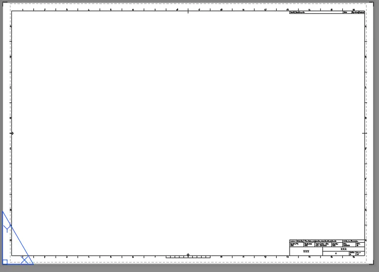
- Click on 'From template'.
- From pop up click on 'Tutorial -mArch'.
- Right click on layout and click on rename and type "Floor Plan-Section A-A".
Step 3 :- Creating Views
- Go to model tab.
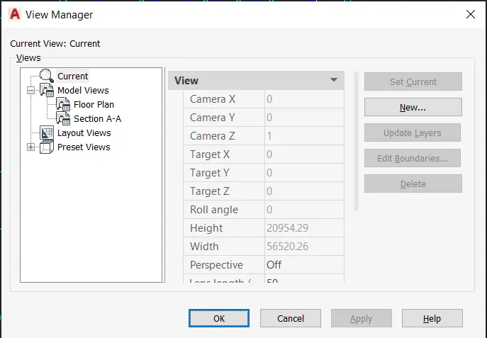
- Type V and press enter.
- Click on new.
- Type name as "Floor Plan".
- Click on define window.
- Select the Floor Plan.
- Click on new.
- Type name as "Section AA".
- Click on define window.
- Select the Section view.
Step 3 :- Creating Viewports
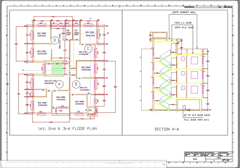
- Draw rectangle from the top of layout of dimensions 400mm x 445mm.
- Draw another rectangle adjacent to the rectangle from the top right corner with dimensions 375mm x 445mm.
- Type "PS" and press enter to go to paper space.
- Type "MV" in command box and click on object in command box.
- Select the first rectangle drawn as object to viewport.
- Type "MS" and press enter to go to model space.
- Type "V" and press enter.
- Select the Floor Plan view created and click on set current and then click okay.
- Change the scale to 1:50/2%.
- Type "PAN" in the command box and press enter and adjust the figure in viewport.
- Type "PS" and press enter to go to paper space.
- Type "MV" in command box and click on object in command box.
- Select the second rectangle drawn as object to viewport.
- Type "MS" and press enter to go to model space.
- Type "V" and press enter.
- Select the Section A-A view created and click on set current and then click okay.
- Change the scale to 1:50/2%.
- Type "PAN" in the command box and press enter and adjust the figure in viewport.
- Type "PS" and press enter to go to paper space.
- Select the two viewports created and go to properties.
- Change the display locked to "YES".
Step 4 :- Changing layers property
- Type "LA" in the command box and press enter.
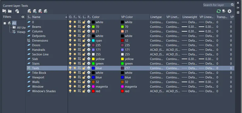
- Change the colour property of Layers of viewport 1 and 2 for better visibility.
- Layers for Viewport 1 & 2 respectively are as follows :-
Step 5 :- Adding Details to Template
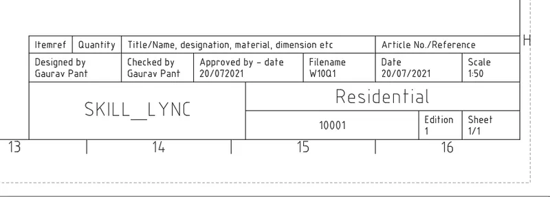
- For changing the data of the attribute goto BATTMAN or double to enter the value.
- Change the values as per the question requirement.
- Give dimensions of the view ports and text regarding scale as 1:50.
Step 6 :- Plotting
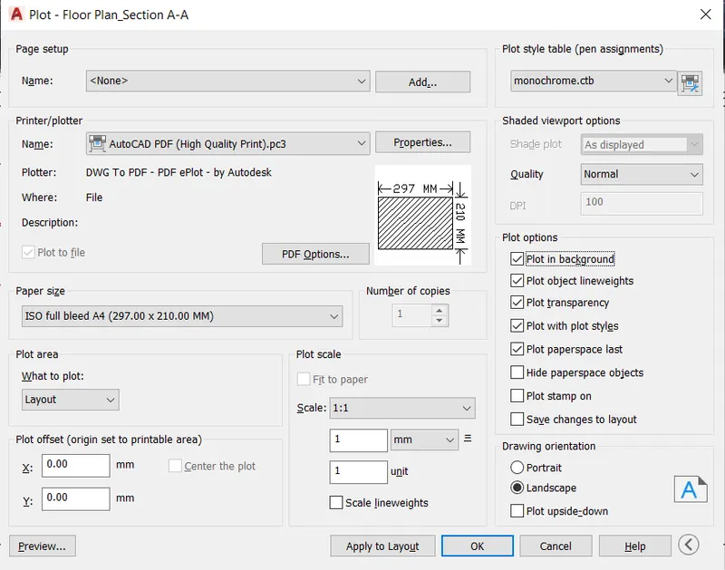
- Type plot and press enter.
- Set name as "Week_10_Q1".
- Change printer to AutoCAD PDF.
- Set paper size as ISO A1.
- Change plot area to "Layout".
- Change plot style table to "monochrome.ctb".
- Check the preview for adjustments.
- Click "OK" on the plot box.
- Select the path and set name.
Result :-
- The result of this question consists of layout of floor plan and section A-A created from standard AutoCAD template "Tutorial-mArch".
Problem 2 :-
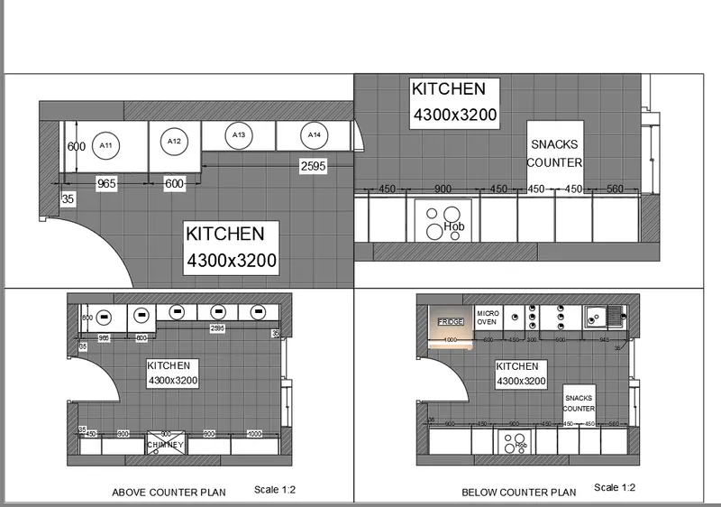
Aim :- To create a layout of the Kitchen drawn in challenge of week 9 and use the scale as shown in the question figure and take a plot using AutoCAD.
Procedure :-
- Open AutoCAD application.
- Type "Un" and press enter.
- Set Units to scale inserted content as "milimeter" and press Enter.
- Sets limits by typing "limits" in command box.
Step 1 :- Importing Drawing from challenge of week 9
- Type xref in command box and press enter.
- Click on 'Attachement'.
- Keep scale as 1.
- Click on insertion point as specify on screen.
- Click on okay and specify the point of insertion.
- Right click on the W9Q1 drawing and select the bind option.
- In pop up click on insert the drawing into W10Q2 along with layers.
Step 2 :- Creating Layout
- Go to layout tab and delete the current viewports available.
- Right click on the layout tab.
- Click on rename and type 'Kitchen Layout W10Q2'
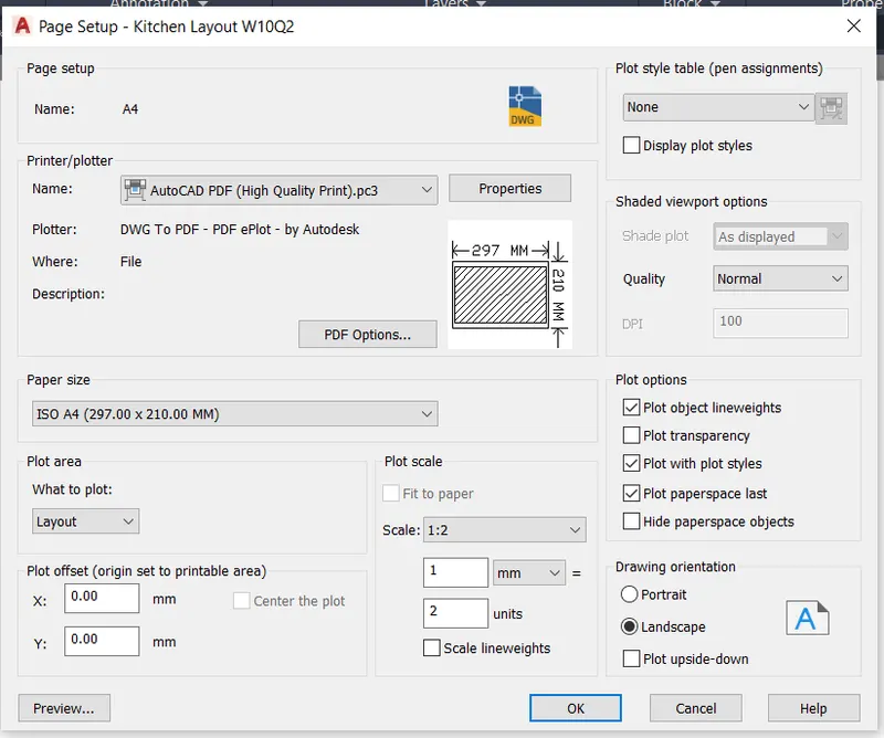
- Go to Page setup manager.
- Click on new.
- Set name as A4.
- Change printer to AutoCAD PDF.
- Set paper size as ISO full bleed A4.
- Change plot area to "Layout".
- Click "ok".
Step 3 :- Creating Views
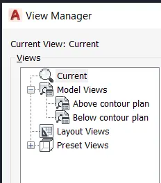
- Go to model tab.
- Type "V" and press enter.
- Click on new.
- Type name as "Below contour plan".
- Click on define window
- Select the "below contour plan" view.
- Click on new
- Type name as "Above contour plan".
- Click on define window.
- Select the "above contour plan" view.
Step 4 :- Creating Viewports
- Type 'mv' and press enter.
- Click on Layer 4 option in the command box and press enter.
- Specify the corner points of view port.
- Type "MS" and press enter to go to model space.
- Click inside of bottom left viewport.
- Type "V" and press enter.
- Click on "Above contour plan" and click on set current.
- Change the scale to 1:2.
- Click inside of bottom right viewport.
- Type "V" and press enter.
- Click on "Below contour plan" and click on set current.
- Change the scale to 1:2.
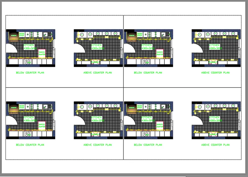
- Create other 2 views as shown in question figure with custom scale 1:1.
Step 6 :- Changing Viewport Layers
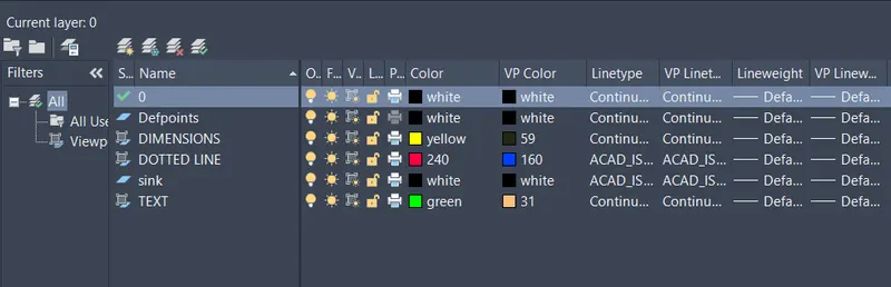
- Type "LA" in the command box and press enter.
- Change the colour property of Layers of all four viewport for better visibility.
- Layers for all Viewports respectively are as follows :-
Step 7 :- Plotting
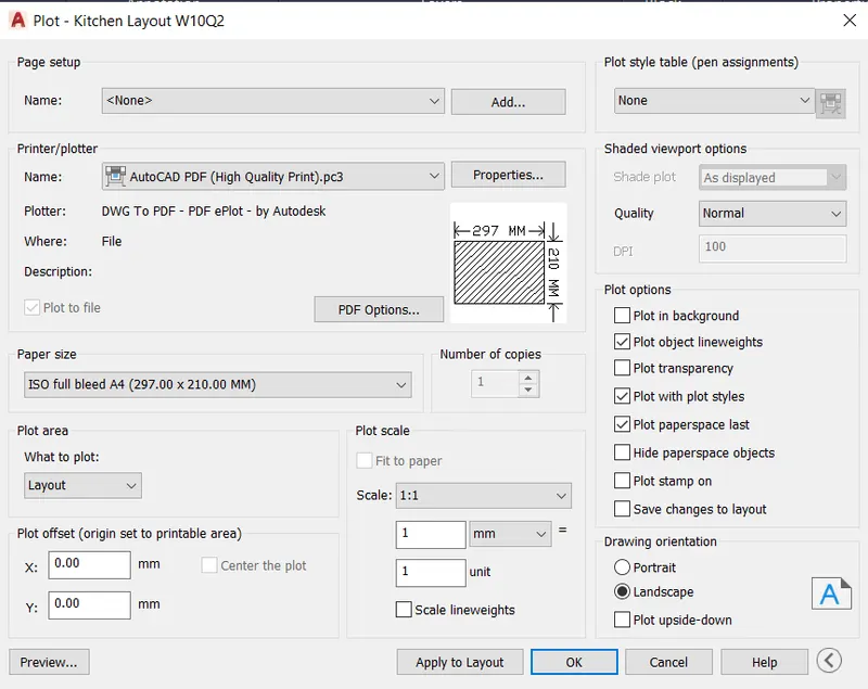
- Type "plot" and press enter.
- Set name as "Kitchen_Layout".
- Change printer to AutoCAD PDF.
- Set paper size as ISO full bleed A4.
- Change plot area to "Layout".
- Change plot style table to "monochrome.ctb".
- Check the preview for adjustments.
- Click "ok" to plot.
- Select the path and set name.
Result :-
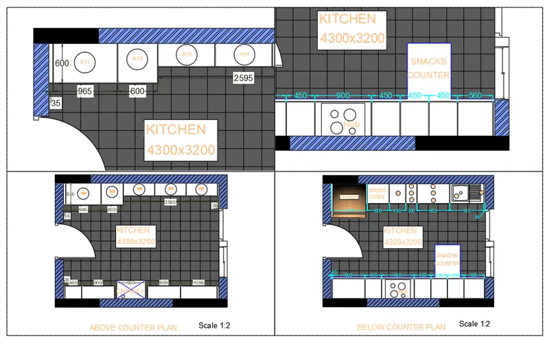
- The result of this question consists of four viewports of kitchen layout plans from challenge of week 9.
Problem 3 :-
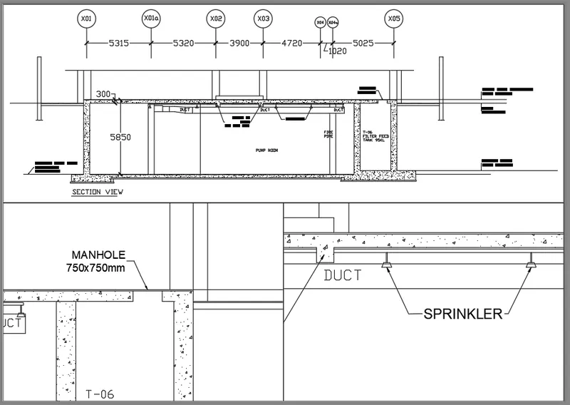
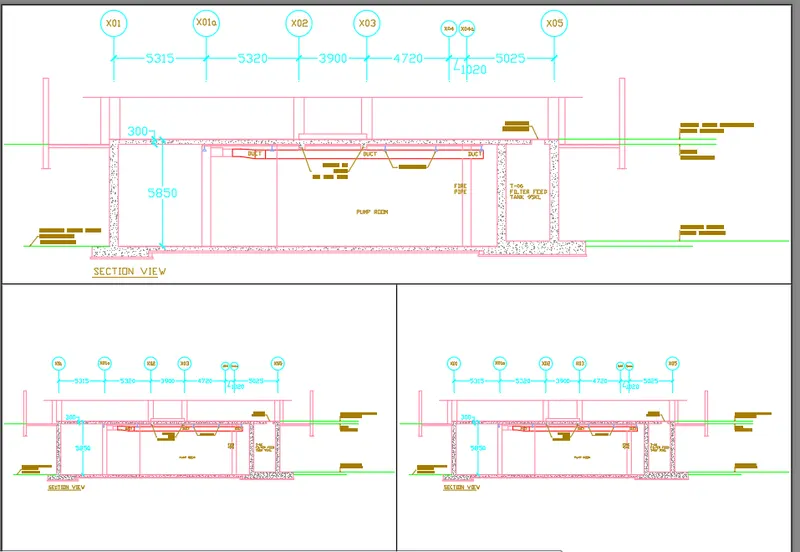
Aim :- To create a layout of the section created in Challenge of week 9, use scale as mentioned in the question Figure and take a plot by using AutoCAD.
Procedure :-
- Open AutoCAD application.
- Type "Un" and press enter.
- Set Units to scale inserted content as "milimeter" and press Enter.
- Sets limits by typing "limits" in command box.
Step 1 :- Importing Drawing from Challenge of week 9
- Type xref in command box and press enter.
- Click on 'Attachement'.
- Keep scale as 1.
- Click on insertion point as specify on screen.
- Click on okay and specify the point of insertion.
- Right click on the W9Q3 drawing and select the bind option.
- In pop up click on insert the drawing into W10Q3 along with layers.
Step 2 :- Creating Layout
- Go to layout tab and delete the current viewports available.
- Right click on the layout tab.
- Click on rename and type "Industrial Building section layout".
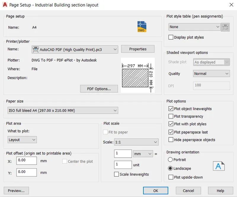
- Go to Page setup manager.
- Click on new.
- Set name as A4.
- Change printer to AutoCAD PDF.
- Set paper size as ISO full bleed A4.
- Change plot area to "Layout".
- Click "ok".
Step 3 :- Creating Views
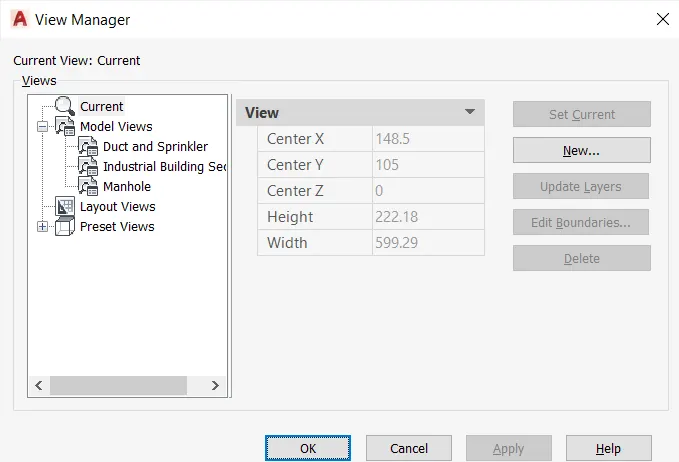
- Go to model tab.
- Type "V" and press enter.
- Click on new.
- Type name as "Industrial Building Section".
- Click on define window.
- Select the entire drawing to fit
- Click on new.
- Type name as "Manhole".
- Click on define window.
- Select the area around the manhole.
- Click on new.
- Type name as "Duct and Sprinkler".
- Click on define window.
- Select the area around the middle sprinkler and right duct.
Step 4 :- Creating Viewports
- Type 'mv' and press enter.
- Click on Layer 3 option in the command box and press enter.
- Specify the corner points of view port.
- Type "MS" and press enter to go to model space.
- Enter viewport arrangement as "Above".
- Type "F" to fit the viewport.
- Type "MS" and press enter to go to model space.
- Click inside of top viewport.
- Type "V" and press enter.
- Click on "Industrial Building" and click on set current.
- Change the scale to 1:100.
- Click inside of bottom left viewport.
- Type "V" and press enter
- Click on "Manhole" and click on set current.
- Change the scale to 1:30.
- Click inside of bottom right viewport.
- Type "V" and press enter.
- Click on "Duct and sprinkler" and click on set current.
- Change the scale to 1:30.
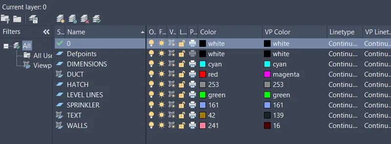
Step 6 :- Changing Viewport Layers
- Type "LA" in the command box and press enter.
- Change the colour property of Layers of all four viewport for better visibility.
- Layers for all Viewports respectively are as follows :-
Step 7 :- Plotting
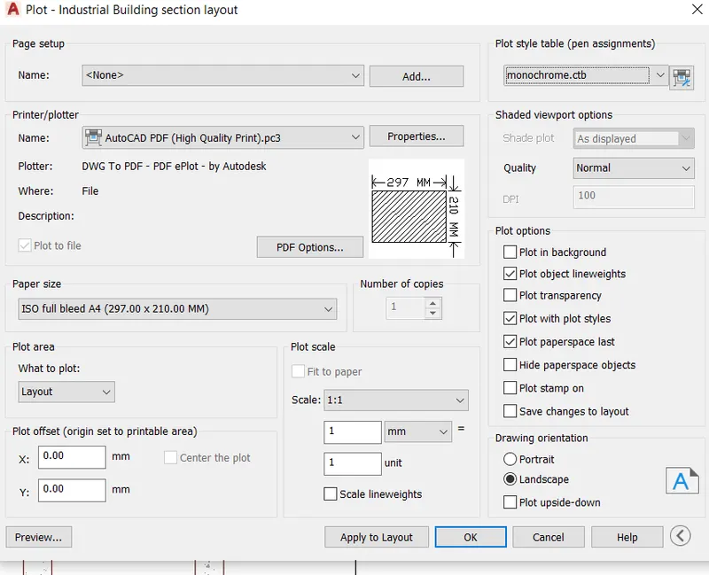
- Type "plot" and press enter.
- Set name as lndustrial_Building_Layout.
- Change printer to AutoCAD PDF.
- Set paper size as ISO full bleed A4.
- Change plot area to "Layout".
- Change plot style table to "monochrome.ctb".
- Check the preview for adjustments.
- Click "ok" to plot.
- Select the path and set name.
Result :-
- The result of this question consists of three viewports of Industrial Building layout plans from challenge of week 9.