Creating Conceptual mass in REVIT and Creation of Sinusoidal curve and a Parametric stadium using Dynamo
Question 1 :-
- Using Dynamo create a set of sinusoidal points and create a curve and create a surface out of the curve.
Answer :-
AIM :-
- To create a set of sinusoidal points and create a curve and create a surface out of the curve using Dynamo.
Introduction to DYNAMO :-
- Dynamo is an Open Source Visual Programming Language for Revit, written by designers and construction professionals. It is a programming language that allows you to type lines of code; while also creating an algorithm that consists of nodes.
- Using Dynamo, one can work with enhanced BIM capabilities in Revit.
- Dynamo and Revit together can be utilized to model and analyze complex geometries, automate repetitive processes, minimize human error and export data to Excel files and other file-types not typically supported by Revit.
- Dynamo can make the design process more efficient, with an intuitive interface and many pre-made scripting libraries available as well.
- User can connect different elements to define the custom algorithms that consist of relationships and sequences.
- These algorithms can be used on many applications, from data processing to geometry generation, with minimal programming code.
- Dynamo is considered a specific Visual Programming tool for designers, as well as a software that can create tools. These tools can use external libraries or any Autodesk product that has an API.
- Dynamo provides the framework as a Revit Internal Generative Design Tool. An understanding of how to work with a Dynamo Script created for Generative Design will help improve knowledge of Generative Design.
- User can be able to manipulate the Revit tool and the way it acts in the process. By adjusting the nodes and values in Dynamo that are linked to Generative Design parameters, one can change the options once the Generative Design tool has been run in Revit.
Procedure :-
Step 1 :-
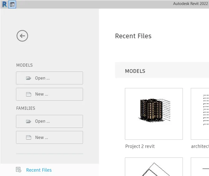
- Double click on the Revit application icon and opens the app.
- Open a new Architectural Template Project File.
Step 2 :-
- Go to "Manage" Tab and Click on "Dynamo" from "Visual Programming" Panel.
- Dynamo window will Open.
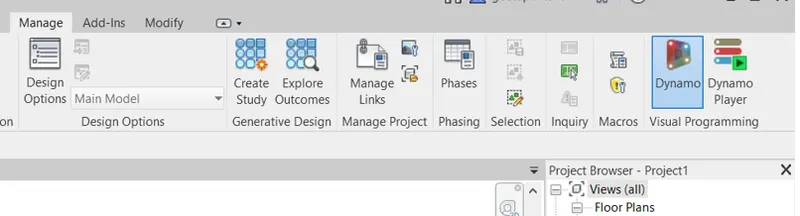
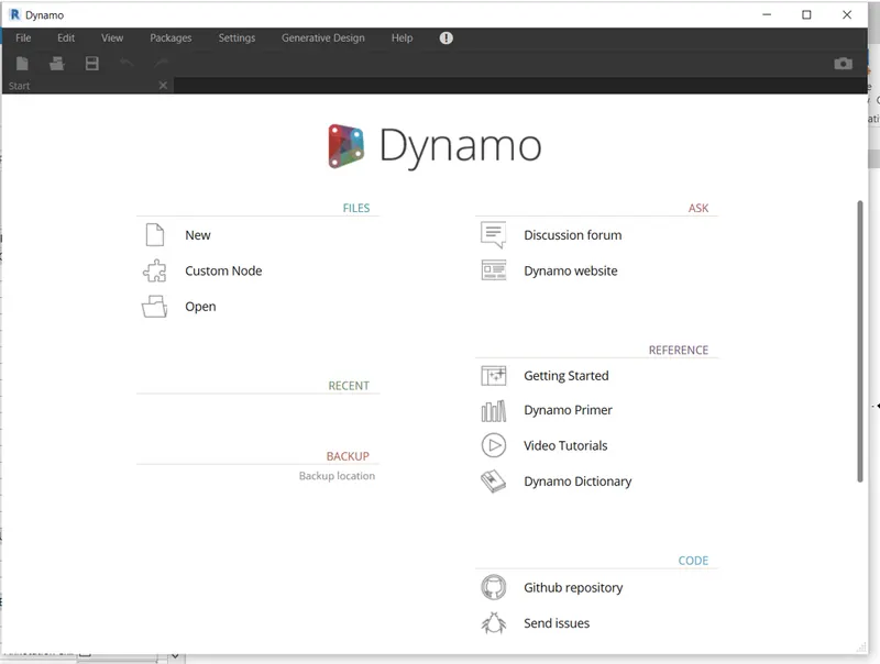
- Click "New" to open dynamo user interface.
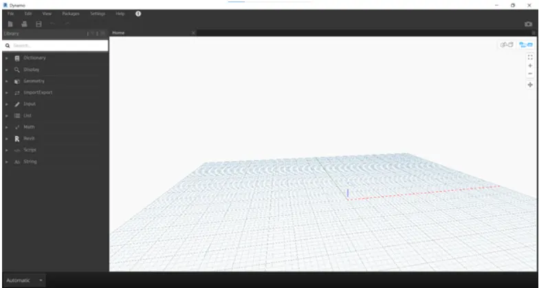
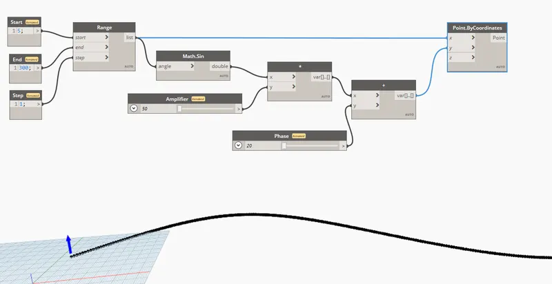
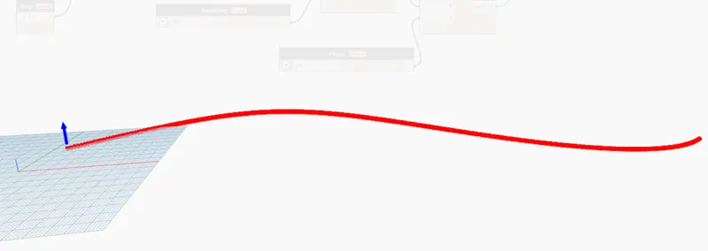
Step 3 :- Creating Sinusoidal Points
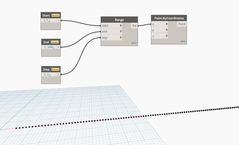
- Go to Search bar and type "Code Block".
- Take three number of code blocks.
- Name them as "Start", "End" and "Step".
- Give values to Start, End and Step block as per choice.
- In this case Values are "Start = 10", "End = 300" and "Step = 1".
- Now Search "Range" and place it in proper position.
- Connect all above created blocks to the Range block.
- Now Search "Point by coordinates" and place the blocks in proper position.
- Connect the Range block to X-coordinate of coordinate block.
- For sin wave, go to library and Search "Math.sin".
- Connect range block to it.
- Insert an "Integer Slider" and Rename it as "Amplifier".
- Set the range as "Min = 50", "Max = 100" and "Step = 1".
- Insert "Product" operator from library and connect "Math.Sin" and "Amplifier" with that.
- Now insert an "Integer Slider" and Rename it as "Phase".
- Set the range as "Min = 20", "Max = 100" and "Step = 1".
- Insert "Add" operator from library and connect "Product" operator and "Phase" with it.
- Finally, connect the "Add" operator to Y-coordinate of coordinate block created earlier.
- Place all the functions boxes in a proper position.
Step 4 :- Creating Sinusoidal curve from Sinusoidal Points
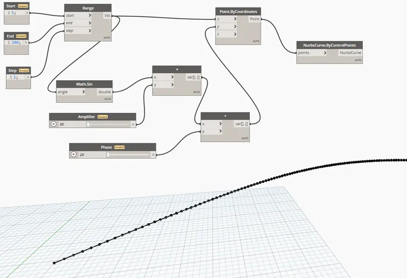
- After creating sinusoidal points, we have to convert them to a curve.
- Now search "Nurbscurve" in library and choose nurbs cuvrve by control points.
- Connect the Points by coordinate block as input for the nurbs curve.
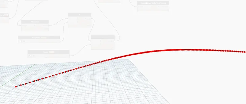
- A line is developed connecting the sinusoidal points.
- Place all the functions boxes in a proper position.
Step 5 :- Creating Surface from Sinusoidal Points
- The next step is to develop surface.
- First create node from selection.
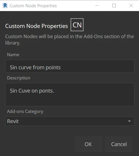
- Select all the boxes and then go to "Edit" and click "Custom Node".
- Add Name, Discription and Category to the Node.
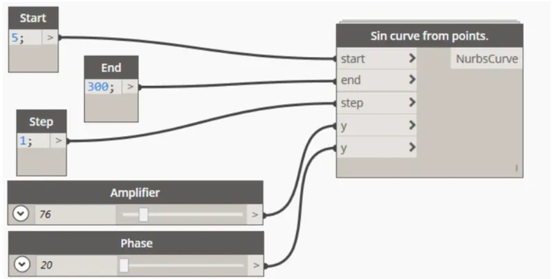
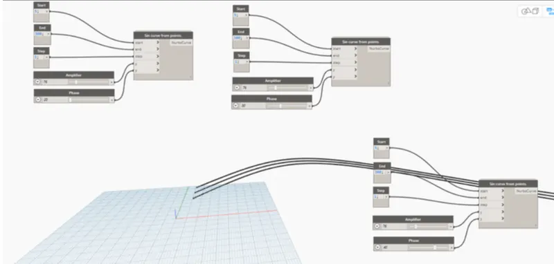
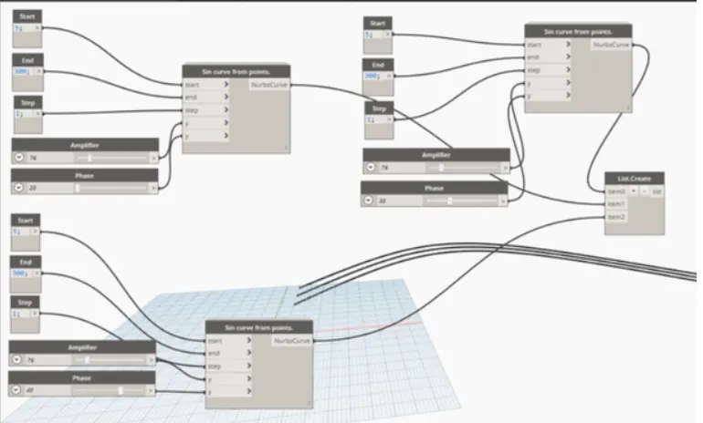
- Now copy this entire block two times to create the surface.
- Adjust phase range to view the two curves that is copied.
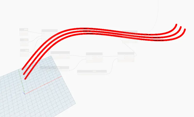
- Now create a list by searching list.create in the search panel of library.
- Add "Items" in the list block.
- Connect all the output of the sine curves as input for the list.
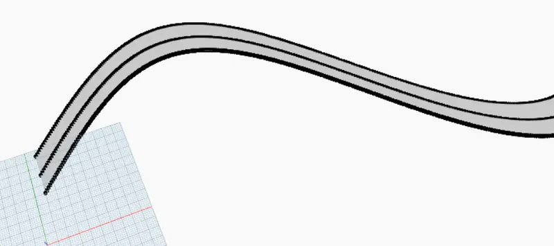
- This will serve as the input for surface by loft block.
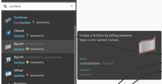
- Now search "Surface by loft" in the search box and connect list output to that box.
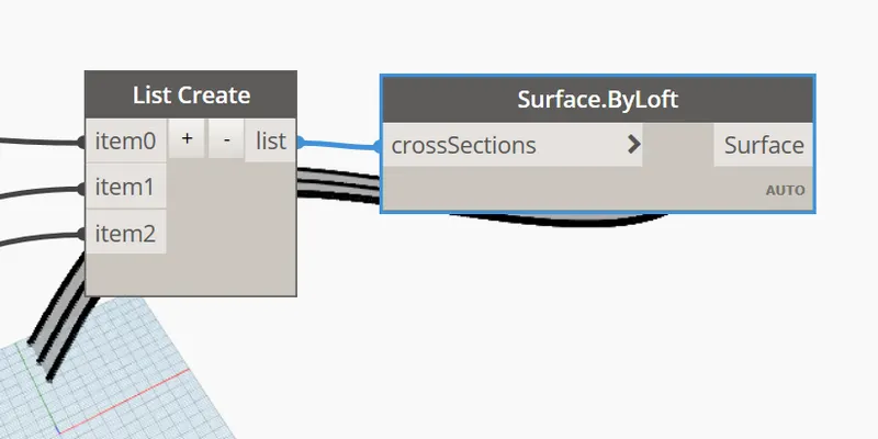
- Sinusoidal Surface has been created.
RESULTS :-
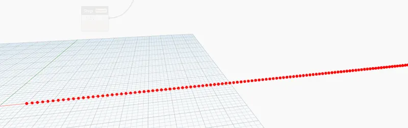
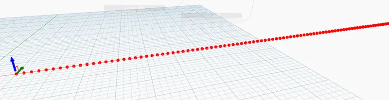
Sinusoidal Points :-
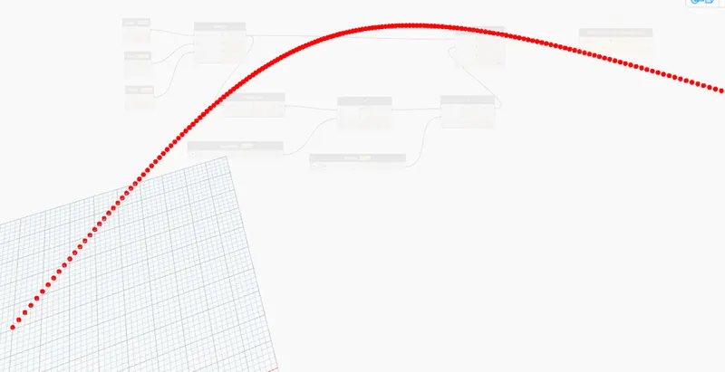
Sinusoidal curve :-
Surface from Sinusoidal Points :-
Question 2 :-
- Create a conceptual layout of floor plan in dynamo. Using the tools available in dynamo link the lines to appropriate model elements in Revit by choosing the wall types and wall parameters. Make use of the sliders to slide through the height of the wall and length of the wall.
Answer :-
AIM :-
- To create a conceptual layout of floor plan using Dynamo.
Procedure :-
Step 1 :-
- Double click on the Revit application icon and opens the app.
- Open a new Architectural Template Project File.
Step 2 :-
- Go to "Manage" Tab and Click on "Dynamo" from "Visual Programming" Panel.
- Dynamo window will Open.
- Click "New" to open dynamo user interface.
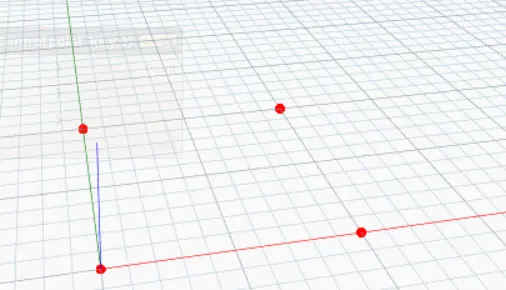
Step 3 :- Creating Control Points and Origin
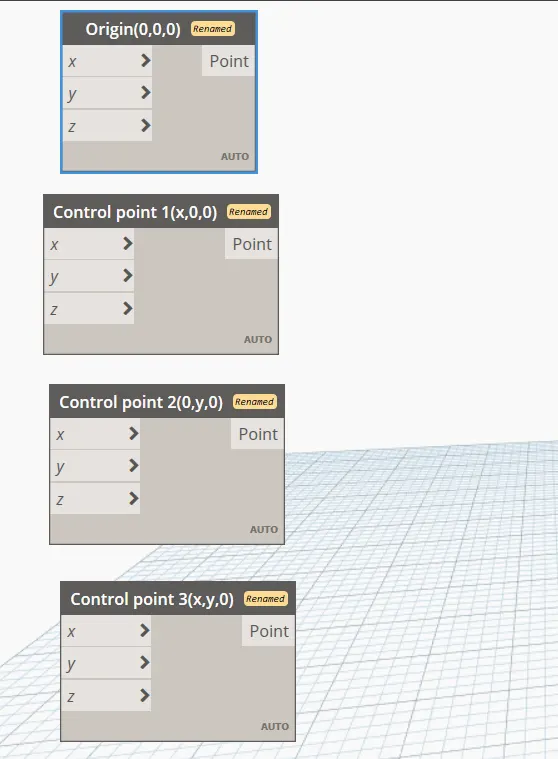
- Go to Search bar and type "Point by coordinates".
- Insert Four number of blocks.
- Name them as "Origin(0,0,0)", "Control point 1(x,0,0)", "Control point 2(0,y,0)" and "Control point 3(x,y,0)".
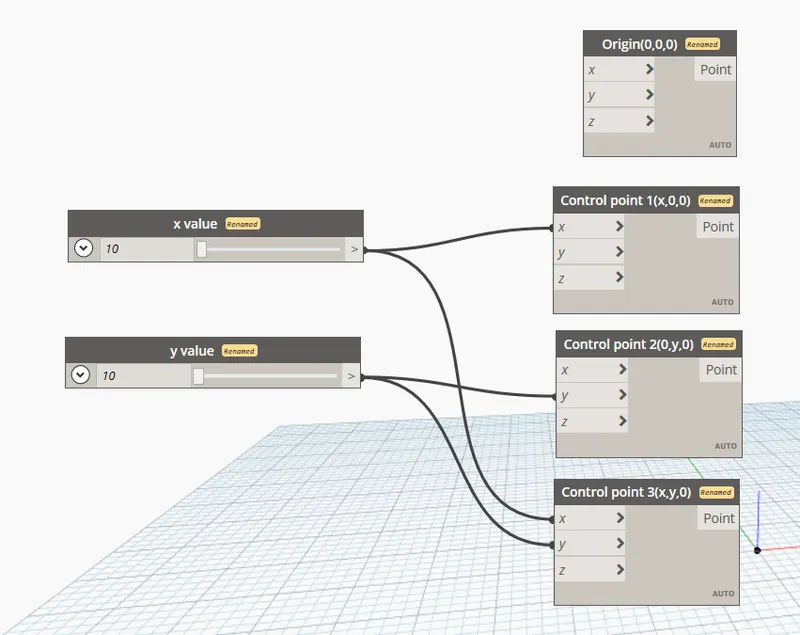
- Insert an "Integer Slider" and Rename it as "x value".
- Insert an "Integer Slider" and Rename it as "y value".
- Give range to both of them as per choice.
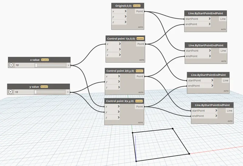
- Connect the "x value" and "y value" to x and y coordinates as given below.
Step 4 :- Creating Lines by connecting Control Points
- Go to Search bar and type "Line" and select "by start point and end point".
- Insert Four number of blocks.
- The input of the boxes are the points created earlier.
- The connection are made as follows :-
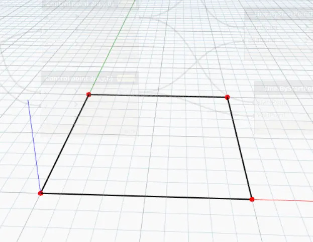
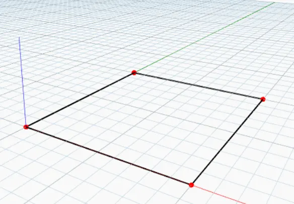
- It will give us the following Layout result :-
Step 5 :- Creating Walls
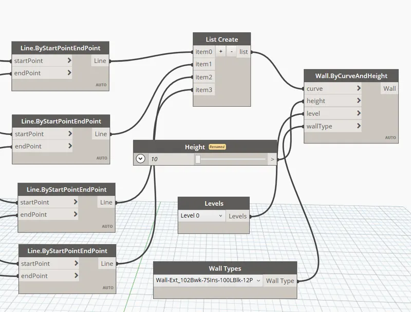
- Go to Search bar and type "Wall" and select "by curve and height".
- For this block, inputs required are Curve, Height, Level and Wall Type.
- For Curve, go to Search bar and type "list.create" and combine all the lines created earlier in this list.
- For Height, go to Search bar and type "slider" and select "integer slider".
- Rename the slider as "Height" and assign the range to it.
- For Level, go to Search bar and type "Level" and it will show the levels available in the revit file.
- Select the required level as per choice.
- For Wall Type, go to Search bar and type "Wall Type" and it will show you the wall types linked in the revit file.
- Select any wall type as per choice.
RESULTS :-
Conceptual Layout of Floor Plan in Dynamo :-
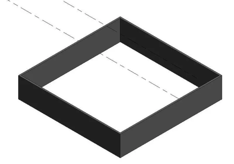
3D View in Revit interface :-
Question 3 :-
- Create an array of model elements in Revit. Use dynamo to vary the properties of model elements by using the slider or code block.
Answer :-
AIM :-
- To create an array of model elements in Revit and vary the properties of model elements with the slider or code block using Dynamo.
Procedure :-
Step 1 :-
- Double click on the Revit application icon and opens the app.
- Open a new Architectural Template Project File.
Step 2 :- Creating Columns
- Go to Architectural Tab and click on architectural column tool.
- Place the column using Array command in longitudinal and transverse direction.

Step 3 :- Changing the properties of model elements using Dynamo
- Go to "Manage" Tab and Click on "Dynamo" from "Visual Programming" Panel.
- Dynamo window will Open.
- Click "New" to open dynamo user interface.
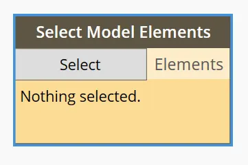
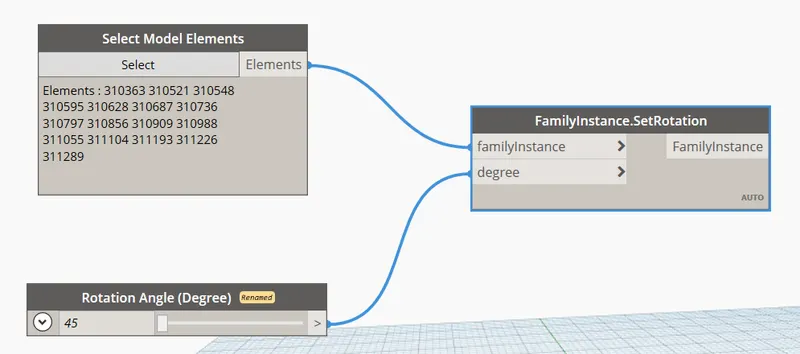
- Now go to Search bar and type "Select Model Element".
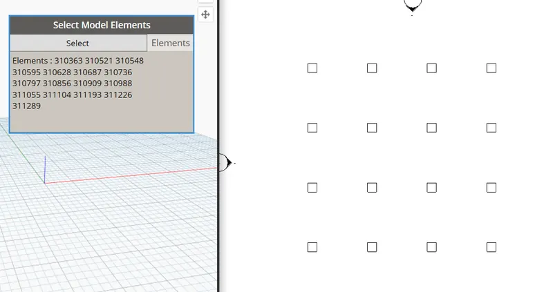
- In the block click on Select and select all the columns from Revit Model.
- Now go to Search bar and type "Integer Slider".
- Rename it as "Rotation Angel (Degree)" and set the range "min = 45" and "max = 90".
- Now go to Search bar and type "Rotation" and select "SetRotation".
- Connect the output of "Select model element" to the input of "family Instance" in "Set Rotaion" block.
- Connect output of "Rotation Angel (Degree)" to the input of "degree" in "Set Rotaion" block.
RESULTS :-
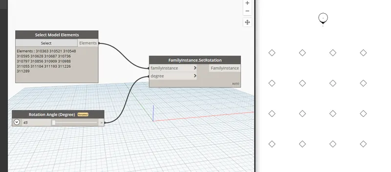
Initial model elements in Revit :-
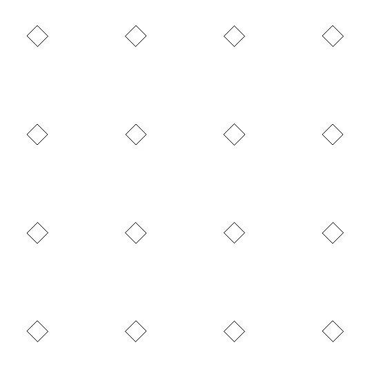
Final Model Element in revit after varying the Properties using Dynamo :-
Question 4 :-
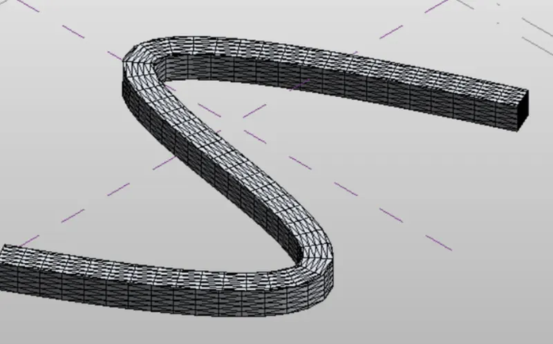
- Create a conceptual mass in Revit and develop a parametric column by dividing the surfaces and apply the concepts similar to used in parametric walkway modelling. Use triangular bent or square shaped panels to add finish to the parametric column.
Answer :-
AIM :-
- To create a Conceptual Mass in Revit and develop a parametric column by dividing the surfaces.
Procedure :-
Step 1 :-
- Double click on the Revit application icon and opens the app.
- Open a "New" in Family block, a dialog box will open.
- Double Click on "Conceotional Mass" and select "Metric mass" and click on "Open".
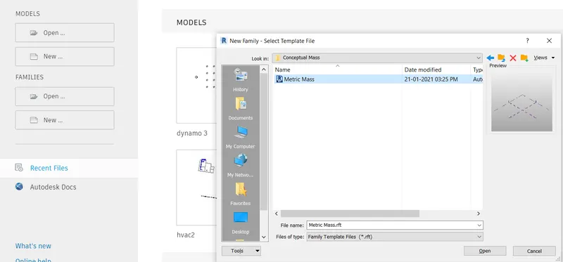
- Foolwing User Interfare will appear :-
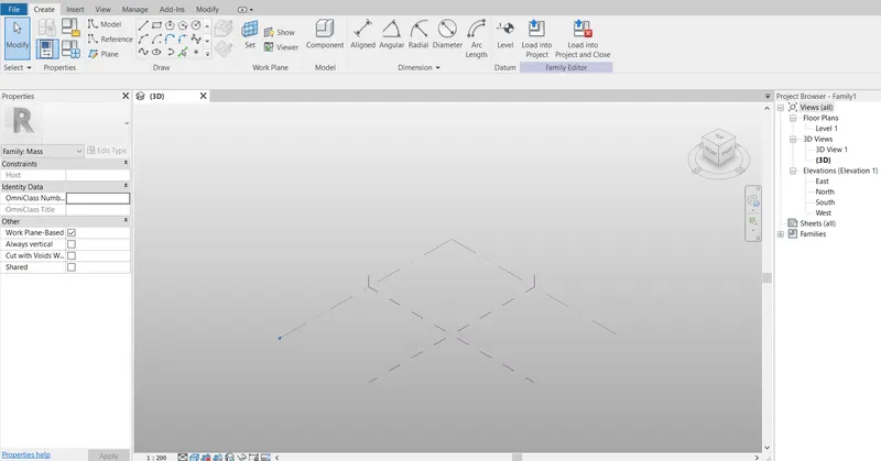
Step 2 :-
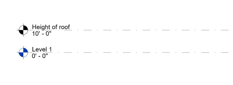
- Go to any Elevation view and create a new level.
- Give the hieght of level as "10 ft" and rename it as "Height of roof".
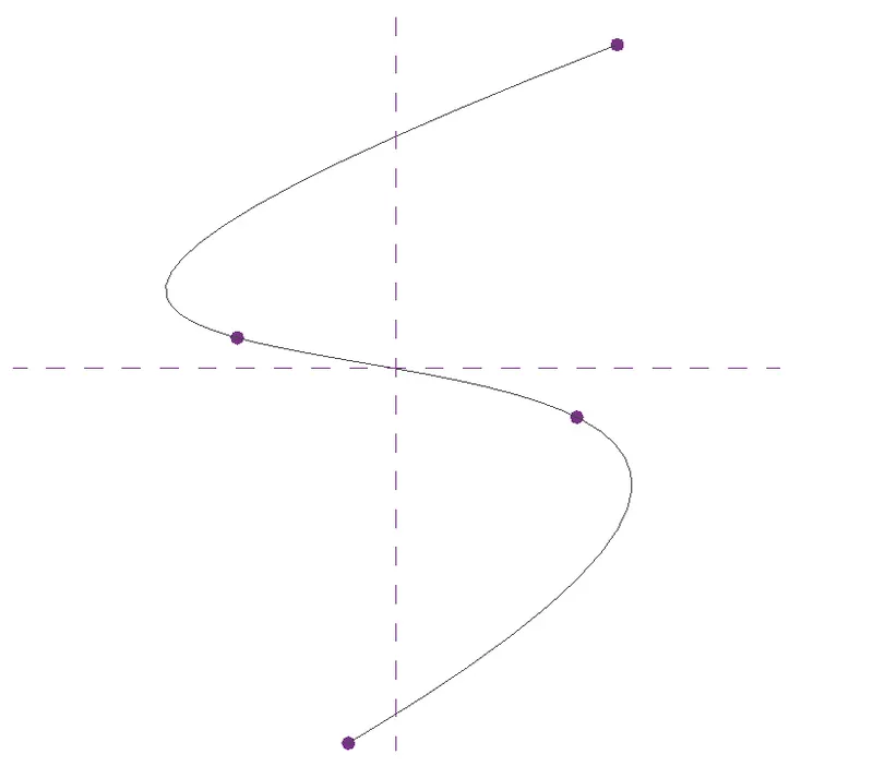
- Go to level 1 and from the create tab, select "spline" tool.
- Draw the desired outline for the walkway.
- Now Select any node of the "spline curve" and from the "Work Plane" panel select "Set" to set the work plane on that end.
- Now go to create tab and select a polygon and set side at 4.
- Draw the polygon on that plane.
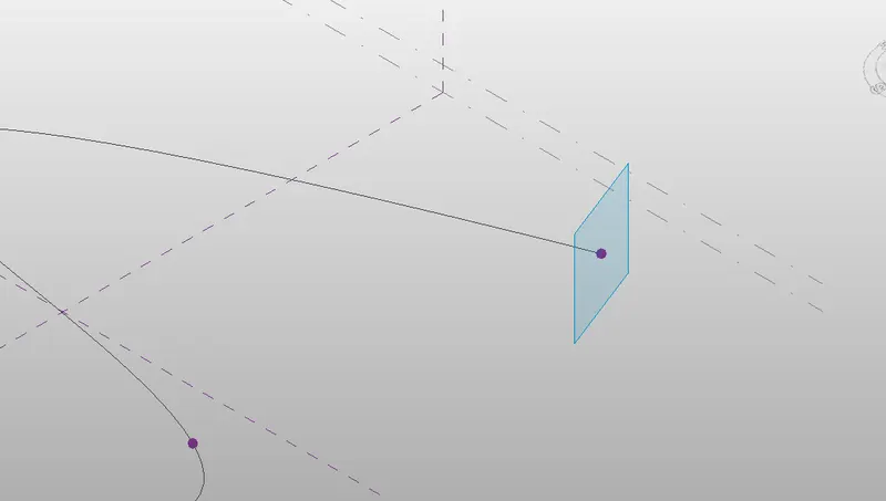
- Repeat the same steps for every nodes of spline and create polygons at each nodes.
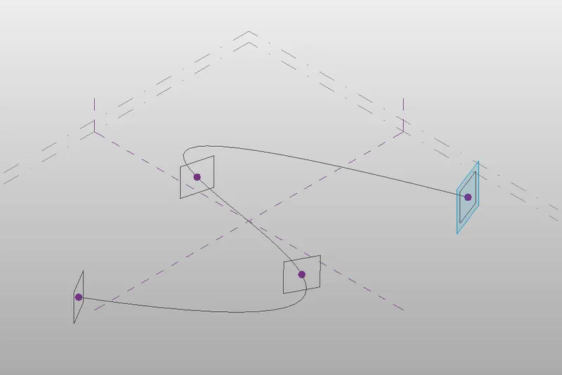
- Select all the Polygons and Spline curve and Click on "Create Form".
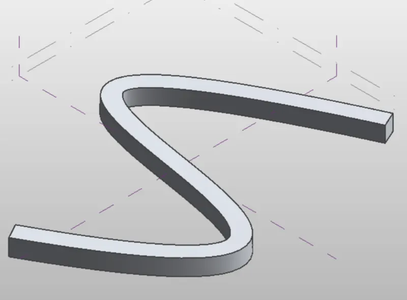
- Select the Entire model and Click on filter and select form only from their.
- Click "OK".
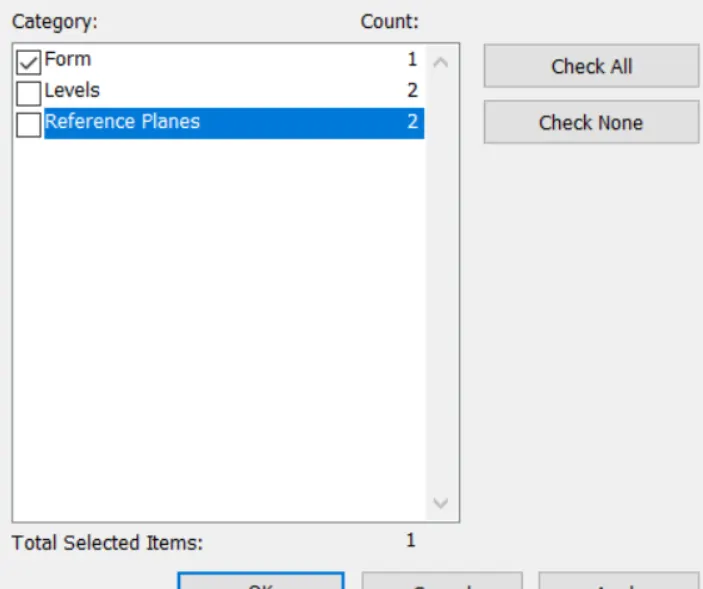
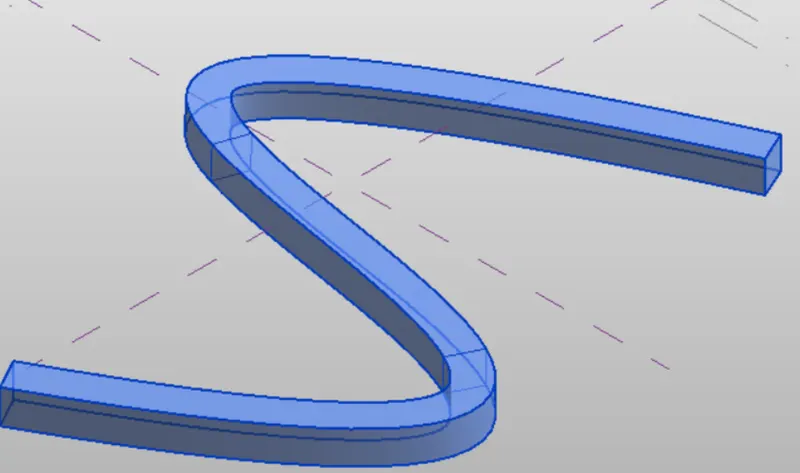
- After selecting the form, Click on divide surface.
- Select "Triangle Bent" Pattern.
RESULTS :-
Conceptual Mass created in Revit :-
Question 5 :-
- Use Dynamo to work on developing a Parametric Stadium. List your parameters and use the visual programming approach to complete the modelling, You can use the concepts discussed in parametric high rise tower in class for reference.
Answer :-
AIM :-
- To develop a Parametric Stadium using Dynamo.
Procedure :-
Step 1 :-
- Double click on the Revit application icon and opens the app.
- Open a new Architectural Template Project File.
Step 2 :-
- Go to "Manage" Tab and Click on "Dynamo" from "Visual Programming" Panel.
- Dynamo window will Open.
- Click "New" to open dynamo user interface.
Step 3 :- Creating Parametric Structure
- Go to Search bar and type "Integer Slider".
- Insert Four number of "Integer Slider".
- Name them as "Number of levels", "Floor to floor height", "Bottom floor rotation" and "Top floor rotation".
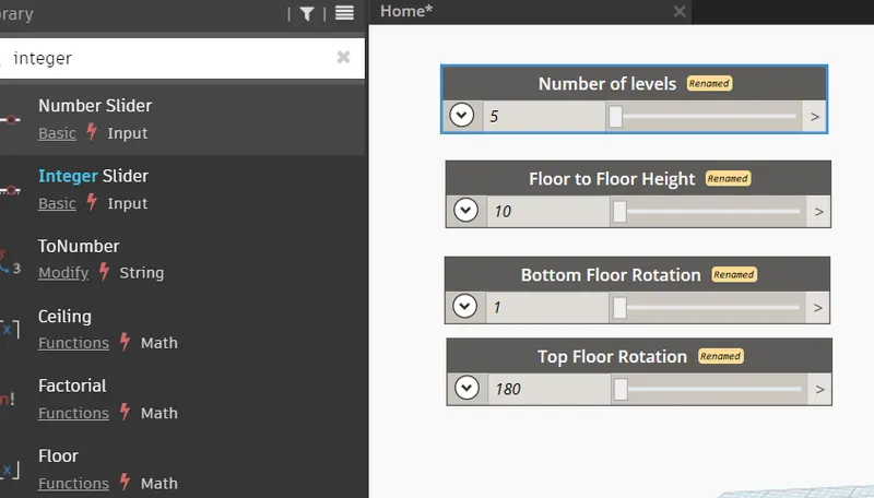
- Change the Range of each Slider as per choice.
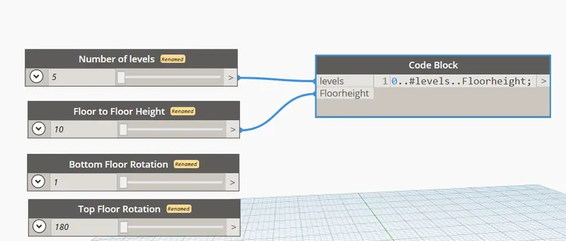
- Go to Search bar and type "Code block".
- Combine Level and Floor height to it and write "0..#levels..Floorheight;" in it.
- Coonect Integer sliders to the code block created.
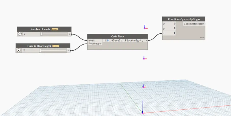
- Go to Search bar and type "coordinates by origin".
- Connect the "code block" as input for "Z coordinate" in the coordinate.
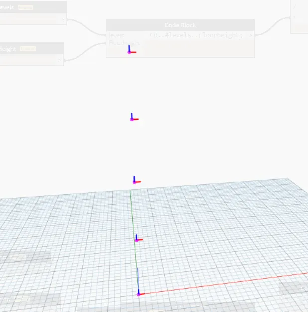
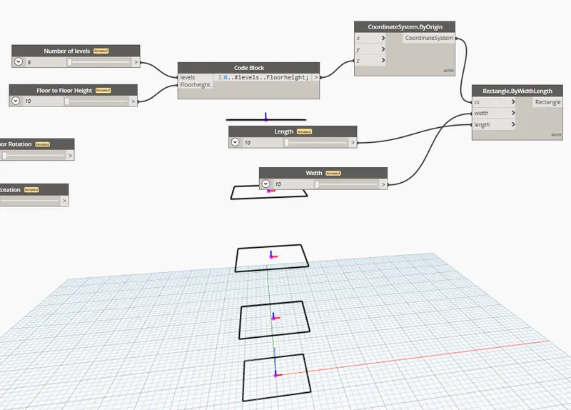
- Go to Search bar and type "Rectangle" and select "by width and length".
- Insert two number of "Integer Slider".
- Name them as "Width" and "Length".
- Now connect the inputs for the "Rectangle block" with earlier created coordinate system and Length and Width sliders.

- Go to Search bar and type "Geometry rotate" and insert it.
- Now from the Library insert a "Origin block", "Z-axis Vector block" and a "Code block".
- Type code in code block as "Top..Bottom..Levels".
- The inputs for this code block are "Bottom floor rotation", "Top floor rotation" and "levels" Sliders created earlier.
- Connect all the blocks and see the results.
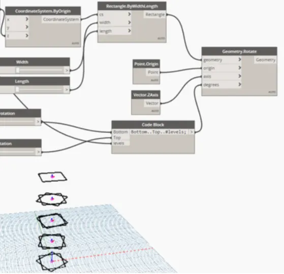
- We can use the Sliders to increase of decrease different parameters as per choice.
- Now go to Search bar and type "Polysurface" and select "by loft".
- Connect "Geometry.rotate" block as input for "Surface by loft".
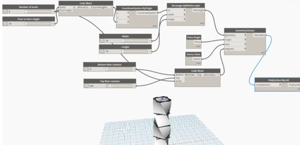
- Similar concepts can be use to prepare Parametric Stadium using Dynamo.
RESULTS :-
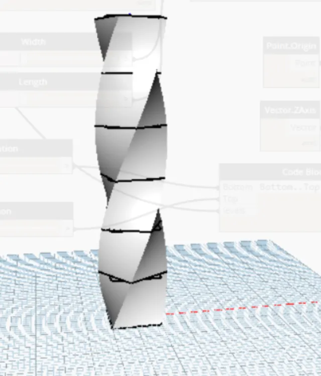
Final Parametric Structure is been created as :-