Creating a Wardrobe detailed drawing, Floor Plan, Kitchen Layout and Column Detail using AutoCad
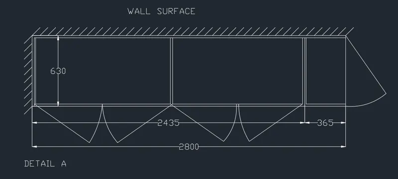
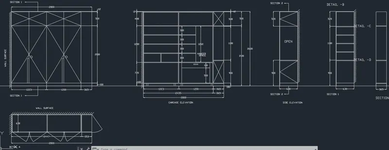
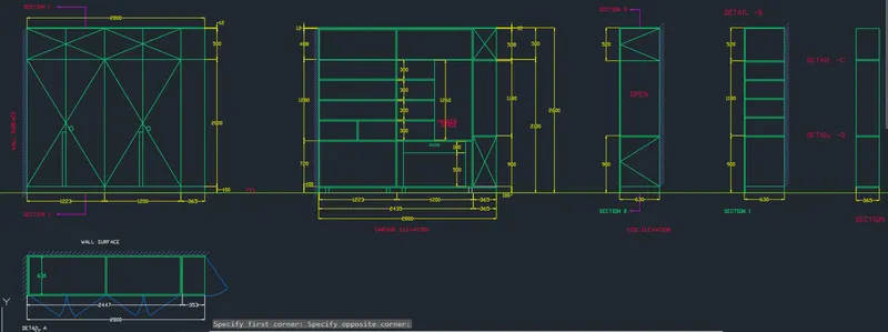
AIM : To draw Plan, Elevation and Section view of a wardrobe as shown in the Figure.
Procedure :-
- Open new file in AutoCAD and Type 'un' in command box and press enter.
- Change unit type to decimal and precision to 0.00 and insertion scale to millimeters.
Step 1 :- Creating Plan View
- Type 'rec' or rectangle in the command box and press enter.
- Specify first corner point by selecting any point on the grid.
- Click on dimensions in command box.
- Specify length for rectangle as 2800 and press enter.
- Specify width for rectangle as 630 and press enter and set the direction in any direction quadrant.
- Type "O" for offset and press enter.
- Specify offset distance as 20 and press enter.
- Select the rectangle drawn earlier to offset and select the inside of the rectangle.
- Type "Explode" in command box and select two rectangles to explode them.
- Type "Move" in command box and move the left two edges to a distance of 12 to right and adjust other line using grips.
- Type "O" for offset and press enter.
- Specify offset distance as 1203 and press enter.
- Select the left edge of inner rectangle and make offset on the right.
- Type "O" for offset and press enter.
- Specify offset distance as 1180 and press enter.
- Select the last offsetted line.
- Type "O" for offset and press enter.
- Specify offset distance as 20 and press enter.
- Select the last offsetted line.
- Again make another offset by selecting the last offsetted line.
- Trim off Extra portions.
- Type "L" and press enter in the command box.
- Draw door gaps using line command.
- Type "TR" in command box and press double enter.
- Trim off extra portions.
- Draw the curve in the plan by using arc command.
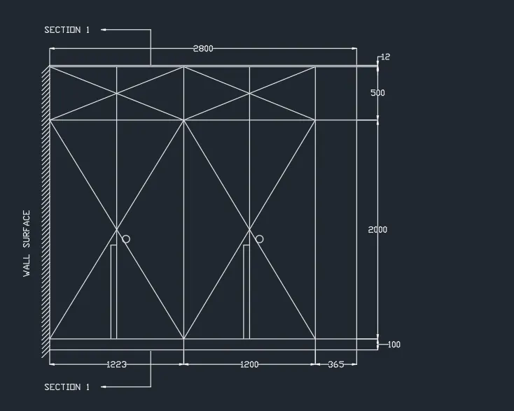
Step 2 :- Creating Front elevation
- Type "rec" in the command box and press enter.
- Specify first corner point by selecting any point on the grid.
- Click on dimensions in command box.
- Specify length for rectangle as 2800 and press enter.
- Specify width for rectangle as 2600 and press enter and set the direction as first quadrant.
- Type "O" for offset and press enter.
- Specify offset distance as 12 and press enter.
- Select the rectangle drawn earlier and click inside of the rectangle.
- Type "Explode" in command box and press enter and explode both rectangles and delete right and bottom edge of inner rectangle.
- Type "O" for offset and press enter.
- Specify offset distance as 1223 and press enter.
- Select the left edge of inner rectangle and click on the right.
- Type "O" for offset and press enter.
- Specify offset distance as 1200 and press enter.
- Select the last offsetted line.
- Type "O" for offset and press enter.
- Specify offset distance as 100 and press enter.
- Select the bottom edge of outer rectangle to offset and click on the top.
- Type "O" for offset and press enter.
- Specify offset distance as 488 and press enter.
- Select the right edge of outer rectangle and click on the left.
- Type "O" for offset and press enter.
- Specify offset distance as 611.5 and press enter.
- Select the left edge of inner rectangle and click on the right.
- Type "O" for offset and press enter.
- Specify offset distance as 600 and press enter.
- Select the line drawn at an offset of 1223 from the left edge and click on the right.
- Type "TR" in command box and press double enter.
- Trim off extra portions.
- Draw cross lines for all the doors.
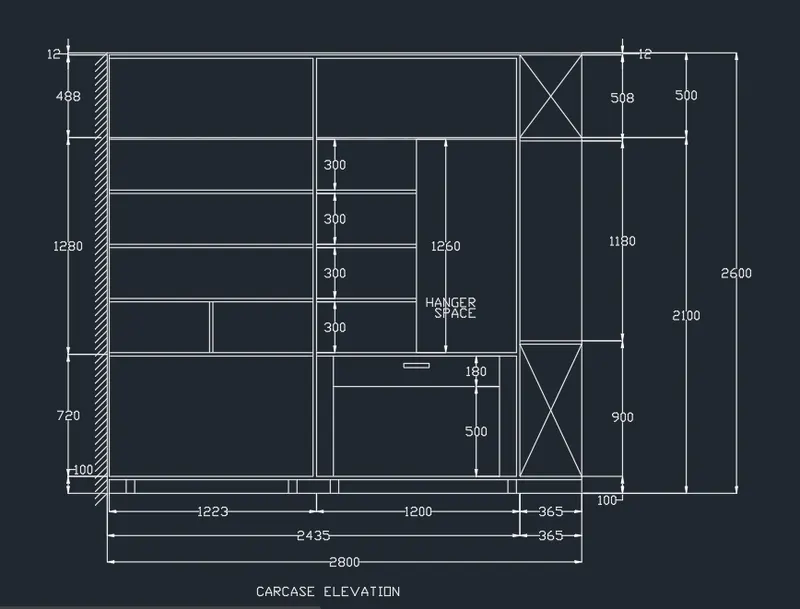
Step 3 :- Creating Car-case elevation
- Type "rec" in the command box and press enter.
- Specify first corner point by selecting any point on the grid.
- Click on dimensions in command box.
- Specify length for rectangle as 2800 and press enter.
- Specify width for rectangle as 2600 and press enter and set the direction as first quadrant.
- Type "O" for offset and press enter.
- Specify offset distance as 12 and press enter.
- Select the rectangle drawn earlier and click inside of the rectangle.
- Type "Explode" in command box and press enter and explode both rectangles and delete right and bottom edge of inner rectangle.
- Type "O" for offset and press enter.
- Specify offset distance as 1223 and press enter.
- Select the left edge of inner rectangle and click on the right.
- Type "O" for offset and press enter.
- Specify offset distance as 1200 and press enter.
- Select the last offsetted line and click on the right.
- Type "O" for offset and press enter.
- Specify offset distance as 100 and press enter.
- Select the bottom edge of outer rectangle and click on the top.
- Type "O" for offset and press enter.
- Specify offset distance as 488 and press enter.
- Select the right edge of outer rectangle and click on the left.
- Type "O" for offset and press enter.
- Specify offset distance as 20 and press enter.
- Select the inner rectangle edges and press enter.
- Type "TR" in command box and press double enter.
- Trim off extra portions.
- Type "O" for offset and press enter.
- Specify offset distance as 680 and press enter.
- Select the bottom edge of inner rectangle offsettrd at 100mm and click on the top.
- Type "O" for offset and press enter.
- Specify offset distance as 320 and press enter.
- Select the last offset line and click on top.
- Select the last offset line and click on top.
- Select the last offset line and click on top.
- Type "O" for offset and press enter.
- Specify offset distance as 20 and press enter.
- Select the last offset line and click on bottom.
- Select the last offset line and click on bottom.
- Select the last offset line and click on bottom.
- Select the last offset line and click on bottom.
- Type "TR" in command box and press double enter.
- Trim off extra portions.
- Type "O" for offset and press enter.
- Specify offset distance as 900 and press enter.
- Select the bottom edge of outer rectangle and click on the top.
- Type "TR" in command box and press double enter.
- Trim off extra portions.
- Type "O" for offset and press enter.
- Specify offset distance as 1180 and press enter.
- Select the last offsetted line and click on the top.
- Create thickness by using offset command and offset distance 20 for both lines.
- Type "L" and press enter in the command box draw cross lines.
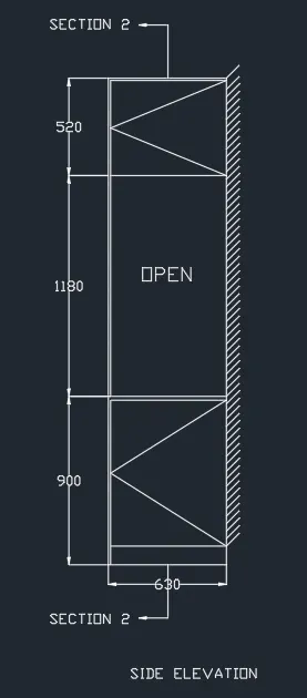
Step 4 :- Creating Side elevation
- Type "rec" in the command box and press enter.
- Specify first corner point by selecting any point on the grid.
- Click on dimensions in command box.
- Specify length for rectangle as 630 and press enter.
- Specify width for rectangle as 2600 and press enter and set the direction as first quadrant.
- Type "O" for offset and press enter.
- Specify offset distance as 20 and press enter.
- Select the rectangle drawn earlier and click inside of the rectangle.
- Type "Explode" in command box and press enter and explode both rectangles.
- Type "O" for offset and press enter.
- Specify offset distance as 100 and press enter.
- Select the bottom edge of outer rectangle and click on the top.
- Type "O" for offset and press enter.
- Specify offset distance as 800 and press enter.
- Select the last offsetted line and click on the top.
- Type "O" for offset and press enter.
- Specify offset distance as 500 and press enter.
- Select the top edge of inner rectangle and click on the bottom.
- Create thickness of 20 for both lines ussing offset command.
- Draw cross line by using line command.
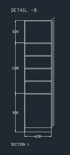
Step 5 :- Creating Section -1 elevation
- Type "rec" in the command box and press enter.
- Specify first corner point by selecting any point on the grid.
- Click on dimensions in command box.
- Specify length for rectangle as 630 and press enter.
- Specify width for rectangle as 2600 and press enter and set the direction as first quadrant.
- Type "O" for offset and press enter.
- Specify offset distance as 20 and press enter.
- Select the rectangle drawn earlier and click inside of the rectangle.
- Type "Explode" in command box and press enter and explode both rectangles.
- Type "O" for offset and press enter.
- Specify offset distance as 100 and press enter.
- Select the bottom edge of outer rectangle and click on the top.
- Type "O" for offset and press enter.
- Specify offset distance as 800 and press enter.
- Select the last offsetted line and click on the top.
- Type "O" for offset and press enter.
- Specify offset distance as 500 and press enter.
- Type "O" for offset and press enter.
- Specify offset distance as 320 and press enter.
- Select the last offset line and click on bottom.
- Select the last offset line and click on bottom.
- Select the last offset line and click on bottom.
- Type "O" for offset and press enter.
- Specify offset distance as 20 and press enter.
- Select all offsetted lines and give them thickness of 20mm.
- Type "TR" in command box and press double enter.
- Trim off extra portions.
Step 6 :- Creating Section -1 elevation
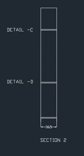
- Type "rec" in the command box and press enter.
- Specify first corner point by selecting any point on the grid.
- Click on dimensions in command box.
- Specify length for rectangle as 365 and press enter.
- Specify width for rectangle as 2600 and press enter and set the direction as first quadrant.
- Type "O" for offset and press enter.
- Specify offset distance as 20 and press enter.
- Select the rectangle drawn earlier and click inside of the rectangle.
- Type "Explode" in command box and press enter and explode both rectangles.
- Type "O" for offset and press enter.
- Specify offset distance as 100 and press enter.
- Select the bottom edge of outer rectangle and click on the top.
- Type "O" for offset and press enter.
- Specify offset distance as 800 and press enter.
- Select the last offsetted line and click on the top.
- Type "O" for offset and press enter.
- Specify offset distance as 500 and press enter.
- Type "O" for offset and press enter.
- Specify offset distance as 20 and press enter.
- Select all offsetted lines and give them thickness of 20mm.
- Type "TR" in command box and press double enter.
- Trim off extra portions.
Step 7 :- Creating Layers
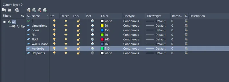
- Type "LA" in command box and press enter.
- Open Layer properties and create new layers by clicking on new layer and select layers and assign the objects on different layers.
RESULT :-
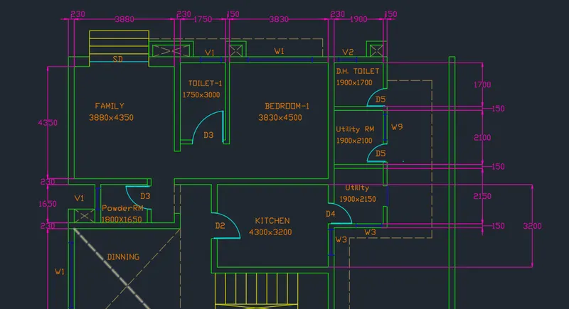
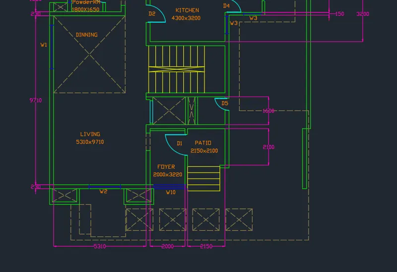
Aim :- To create the given floor plan using proper drafting tools in AutoCAD.
Procedure :-
- Open new file in AutoCAD and Type 'un' in command box and press enter.
- Change unit type to decimal and precision to 0.00 and insertion scale to millimeters.
- Size of Doors and Windows are as followed :-
- Door 1 or D1 as 1200mm X 2200mm
- Door 2 or D2 as 1000mm X 2100mm
- Door 3 or D3 as 900mm X 2100mm
- Door 4 or D4 as 800mm X 2100mm
- Door 5 or DS as 700mm X 2100mm
- Slide Door or SD as 2300mm X 2100mm
- Window 1 or W1 as 2500mm X 1500mm
- Window 2 or W2 as 2300mm X 1500mm
- Window 3 or W3 as 1000mm X 1500mm
- Window 5 or WS as 1100mm X 1500mm
- Window 9 or W9 as 900mm X 1500mm
- Window 10 is a box glass opening
- Ventilator 1 or V1 as 800mm X SOOmm
- Ventilator 2 or V2 as 700mm X SOOmm
Step 1 :- Starting from left to right and top to bottom
- Type "XL" in command box and press enter.
- Click on horizontal and select any point on the screen.
- Type "XL" in command box and press enter.
- Click on vertical and select any point on the horizontal xline.
- Type "O" for offset and press enter.
- Specify offset distance as 230 and press enter.
- Select horizontal xline and click on bottom.
- Select vertical xline and click on right.
- Type "O" for offset and press enter.
- Specify offset distance as 3880 and press enter.
- Select the vertical off set xline of wall thickness and click on right.
- Type "O" for offset and press enter.
- Specify offset distance as 230 and press enter.
- Select the last offsetted line and click on the right.
- Type "O" for offset and press enter.
- Specify offset distance as 1750 and press enter.
- Select the last vertical offset line and click on right.
- Type "O" for offset and press enter.
- Specify offset distance as 150 and press enter.
- Select the last vertical offset line and click on right.
- Type "O" for offset and press enter.
- Specify offset distance as 3830 and press enter.
- Select the last vertical offset line and click on right.
- Type "O" for offset and press enter.
- Specify offset distance as 230 and press enter.
- Select the last vertical offset line and click on right.
- Type "O" for offset and press enter.
- Specify offset distance as 1900 and press enter.
- Select the last vertical offset line and click on right.
- Type "O" for offset and press enter.
- Specify offset distance as 150 and press enter.
- Select the last vertical offset line and click on right.
- Type "O" for offset and press enter.
- Specify offset distance as 3000 and press enter.
- Select the last horizontal offset xline of wall thicknessand click on bottom.
- Type "O" for offset and press enter.
- Specify offset distance as 150 and press enter.
- Select the last vertical offset line and click on bottom.
- Type "O" for offset and press enter.
- Specify offset distance as 4350 and press enter.
- Select the last horizontal offset xline of wall thicknessand click on bottom.
- Type "O" for offset and press enter.
- Specify offset distance as 230 and press enter.
- Select the last vertical offset line and click on bottom.
- Type "TR" in command box and press double enter.
- Trim off extra portions and leave the space for doors.
Step 2 :-
- Type "O" for offset and press enter.
- Specify offset distance as 9710 and press enter.
- Select horizontal offset xline and click on bottom.
- Type "O" for offset and press enter.
- Specify offset distance as 230 and press enter.
- Select the last offsetted line and give the wall thickness.
- Type "O" for offset and press enter.
- Specify offset distance as 3220 and press enter.
- Select the last offsetted line and click on the top.
- Type "O" for offset and press enter.
- Specify offset distance as 150 and press enter.
- Select the last offset line and click on top.
- Type "O" for offset and press enter.
- Specify offset distance as 230 and press enter.
- Select the last offsetted line and give the wall thickness.
- Type "O" for offset and press enter.
- Specify offset distance as 1600 and press enter.
- Select the last offsetted line and click on the top.
- Type "O" for offset and press enter.
- Specify offset distance as 230 and press enter.
- Select the last offset line and click on top.
- Type "TR" in command box and press double enter.
- Trim off extra portions and leave the space for doors.
- and make the area of dining room, foyer and patio as per the question.
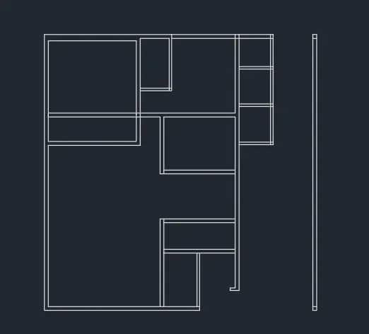
Step 2 :- Creating Layers
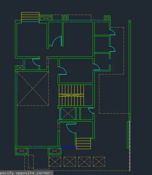
- Type "LA" in command box and press enter.
- Open Layer properties and create new layers by clicking on new layer and select layers and assign the objects on different layers.
- Give dimensions within the dimension layer.
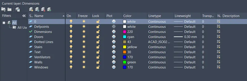
RESULTS :-
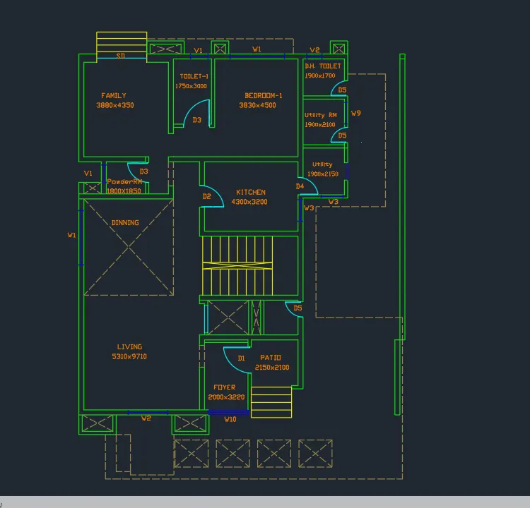
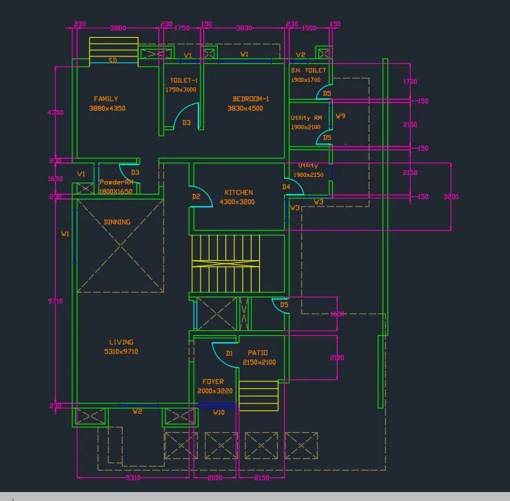
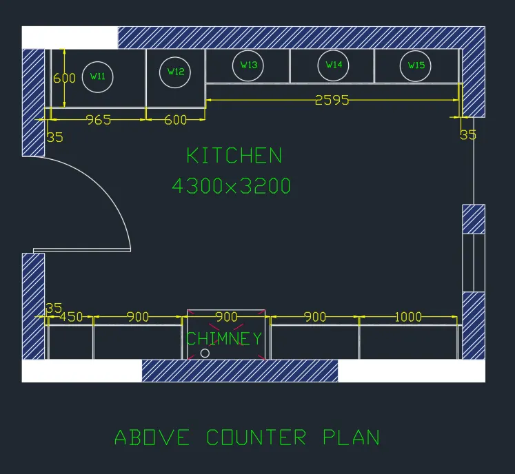
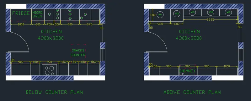
Aim :- To create the Kitchen layout plans as shown in the figure using AutoCAD.
Procedure :-
- Open new file in AutoCAD and Type 'un' in command box and press enter.
- Change unit type to decimal and precision to 0.00 and insertion scale to millimeters.
- Size of Doors and Windows are as followed :-
- Door 1 or D1 as 1000mm X 2100mm
- Door 2 or D2 as 1000mm X 2100mm
- Window 1 or W1 as 900mm X 1500mm
Step 1 :- Creating Below contour plan
- Type "rec" in the command box and press enter.
- Specify first corner point by selecting any point on the grid.
- Click on dimensions in command box.
- Specify length for rectangle as 4300 and press enter.
- Specify width for rectangle as 3200 and press enter and set the direction as first quadrant.
- Type "O" for offset and press enter.
- Specify offset distance as 230 and press enter.
- Select the rectangle drawn earlier and click inside of the rectangle.
- Type "Explode" in command box and press enter and explode both rectangles.
- Create door opening using Line and Trim command.
- Type "O" for offset and press enter.
- Specify offset distance as 600 and press enter.
- Select the bottom edge of inner rectangle and click on the top.
- Type "O" for offset and press enter.
- Specify offset distance as 40 and press enter.
- Select the last offsetted line and click on the top.
- Type "O" for offset and press enter.
- Specify offset distance as 35 and press enter.
- Select the line drawn earlier and click on right.
- Type "O" for offset and press enter.
- Specify offset distance as 900 and press enter.
- Select the last offset line and click on right.
- Type "O" for offset and press enter.
- Specify offset distance as 450 and press enter.
- Select the last offset line and click on right.
- Type "O" for offset and press enter.
- Specify offset distance as 900 and press enter.
- Select the last offset line and click on right.
- Type "O" for offset and press enter.
- Specify offset distance as 450 and press enter.
- Select the last offset line and click on right.
- Select the last offset line and click on right.
- Select the last offset line and click on right.
- Type "O" for offset and press enter.
- Specify offset distance as 630 and press enter.
- Select the last offset line and click on right.
- Type "O" for offset and press enter.
- Specify offset distance as 10 and press enter.
- Select the bottom edge of inner rectangle and click on top.
- Type "O" for offset and press enter.
- Specify offset distance as 20 and press enter.
- Select the line offset at 35 from left and click on right.
- Repeat the same procedure for all offset lines drawn above with the given offset distance.
- Create hob using rectangle and circle commands.
- Type "O" for offset and press enter.
- Create the close areainside the wall thickness of given offset distance and create "Hatch".
- Type "Hatch" in the command box and set the scale of hatch as per requirement.
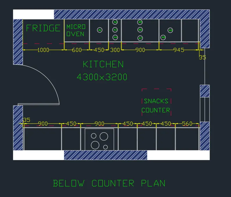
Step 1 :- Creating Above contour plan
- Follow the same steps done in the below contoure plan of kitchen.
- Just the offset distance are changed.
- Use the text command and type the required text.
- Choose the text style.
RESULT :-
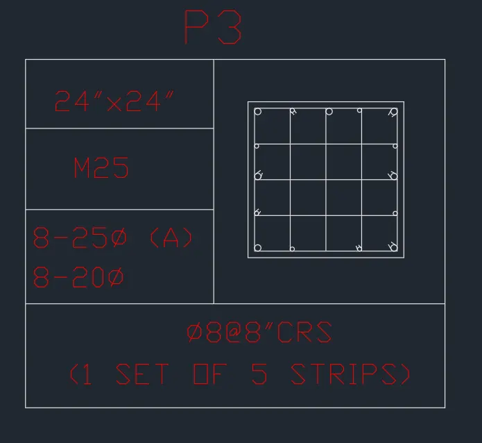
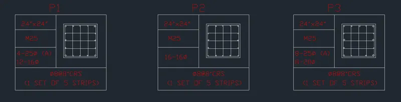
Aim :- To create a column schedule as given in the figure using AutoCAD.
Procedure :-
- Open new file in AutoCAD and Type 'un' in command box and press enter.
- Change unit type to Engineering and "inches".
Step 1 :- Creating Table :-
- Type "REC' in command box to create a rectangle and press enter.
- Click on dimensions in command box and specify the length of rectangle as 60" and width of rectangle as 60".
- Type "EXPLODE" in the command box and press enter.
- Select the rectangle and press enter. Press "esc".
- Type "O" for offset command and press enter.
- Specify the offset distance as 2' and press enter.
- Select the left egde of the rectangle and click on right side.
- Type "O" for offset command and press enter.
- Specify the offset distance as 1' and press enter.
- Select the bottom egde of the rectangle and click on top side.
- Now divide the line segment into 3 parts using divide tool.
- use line command and draw three blocks on left side of table by joining points.
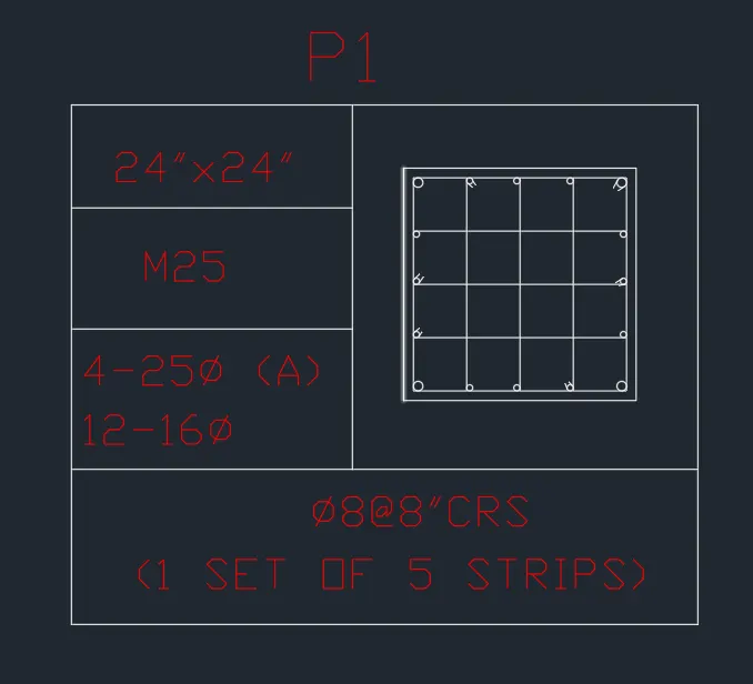
Step 2 :- Creating P1 Column
- Type "REC' in command box to create a rectangle and press enter.
- Click on dimensions in command box and specify the length of rectangle as 24" and width of rectangle as 24".
- Type "EXPLODE" in the command box and press enter.
- Select the rectangle and press enter. Press "esc".
- use the divide command and divide the blocks in 4 blocks and join it by lines.
- Type "C" for circle and press enter and select tangent, tangent, radius from command box and mark the first and second tangents as top and side line of column and make a circle of radius 12.5mm or 0.492126".
- Next use mirror command and make the same circle copy to each corners of rectangle.
- Next type "C" for circle in command box and make bar of 16mm
- radius = 0.314961.
- Use copy command to move the circle in required place.
- write the written text in the question.
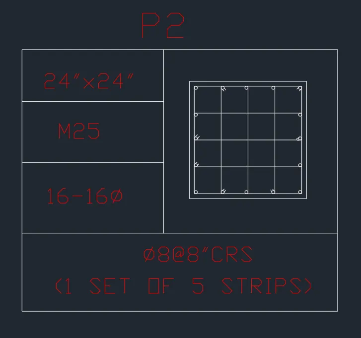
Step 2 :- Creating P2 Column
- Type "REC' in command box to create a rectangle and press enter.
- Click on dimensions in command box and specify the length of rectangle as 24" and width of rectangle as 24".
- Type "EXPLODE" in the command box and press enter.
- Select the rectangle and press enter. Press "esc".
- use the divide command and divide the blocks in 4 blocks and join it by lines.
- Type "C" for circle and press enter and select tangent, tangent, radius from command box and mark the first and second tangents as top and side line of column and make a circle of radius 8mm or 0.314961".
- Next use mirror command and make the same circle copy to each corners of rectangle.
- Use copy command to move the circle in required place.
- write the written text in the question.
Step 2 :- Creating P3 Column :-
- Type "REC' in command box to create a rectangle and press enter.
- Click on dimensions in command box and specify the length of rectangle as 24" and width of rectangle as 24".
- Type "EXPLODE" in the command box and press enter.
- Select the rectangle and press enter. Press "esc".
- use the divide command and divide the blocks in 4 blocks and join it by lines.
- Type "C" for circle and press enter and select tangent, tangent, radius from command box and mark the first and second tangents as top and side line of column and make a circle of radius 12.5mm or 0.492126".
- Next use mirror command and make the same circle copy to each corners of rectangle.
- Again make the circle of radius 10mm or 0.393701.
- Use copy command to move the circle in required place.
- write the written text in the question.
RESULT :-
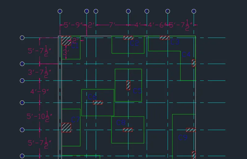
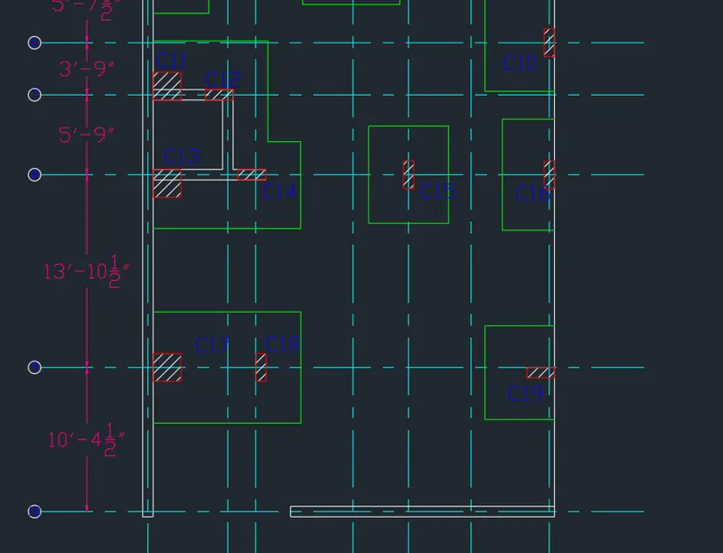
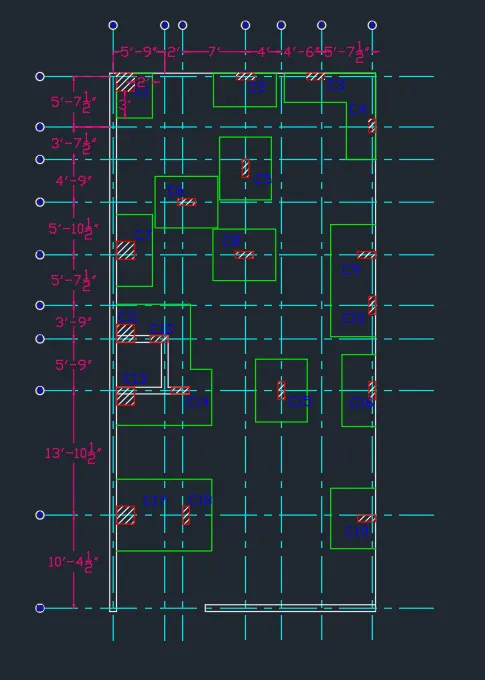
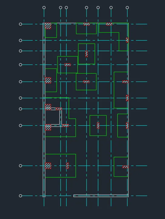
Aim :- To create a raft foundation layout plan as shown in figure
Procedure :-
- Open new file in AutoCAD and Type 'un' in command box and press enter.
- Change unit type to Engineering and "inches".
Step 1 :- Creating center lines
- Change line type to CENTER in properties toolbar.
- Change line type scale to 25 in this case.
- Type 'xl' or xline in command box and press enter.
- Click on Vertical.
- Select any point on the screen.
- Type 'o' and press enter.
- Specify offset distance: Type 5'9" and press enter
- Select object to offset Select the first xline drawn and click on right.
- Press enter twice.
- Specify offset distance as 2' and press enter.
- Select the last offset line drawn and click on right.
- Continue this process and give the required offset distance according to the question adn complete the center line.
- bothe horizontal and vertical center line should be drawn according to question requirement.
Step 2 :- Creating column layouts
- Make the column layouts of all sizes as per the question.
- place it in the the required places as per the question requirement.
Step 3 :- Creating Layers
- Type "LA" in command box and press enter.
- Open Layer properties and create new layers by clicking on new layer and select layers and assign the objects on different layers.
- Give dimensions within the dimension layer.
Step 4 :- Creating Texts
- Type "dt" in command box and make the description and type the text you wants to enter.
- copy the text and place it at different locations and change the text by using "edittext " command.
- Choose the text style by using "ST" command.
- Change the colour of the text either by using layer or overwritting through property tab.
RESULT :-