Planetary gear mechanism MBD simulation
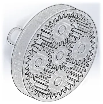
AIM: Motion Study of Planetary Gear Train
OBJECTIVE: MBD motion study of Planetary gear train, comparison of different cases.
Key Points:
- What is Gear, Types and Application
- Gear Terminology
- Introduction to Planetary Gear Train, its working and application.
- Calculating design parameters for planet, sun and ring gear.
- Design of Epicyclic Gear train (Planetary gear train) components
- Setting up motion study for three different cases
- Plotting each study report and verifying result
- Conclusion
- References
What is Gear?
A gear is small circular rotating part which has teeth on its circular profile. Gears are also known as toothed wheels. It is used to change rotation direction from input to output, to transmit power and torque. Gears are used when the distance between the driver and follower is very small.
Classification:
Gears are classified based on
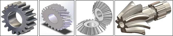
Axis of the shafts:
- Spur gear: two parallel and co-planer axes
- Helical gear: teeth are inclined to axis of rotation
- Bevel gear: two non-parallel or non-intersecting but co-planer axes
- Skew or spiral gears: two non-parallel or non-intersecting and non-coplanar axes.
|
a) Spur Gear b) Helical gear c) Bevel gear d) Spiral gear |
Type of gear meshing:
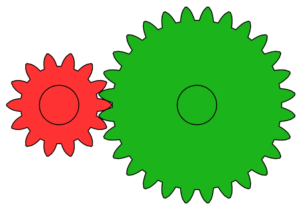
- External gearing: Gear teeth mesh externally
- Internal gearing: Gear teeth mesh internall
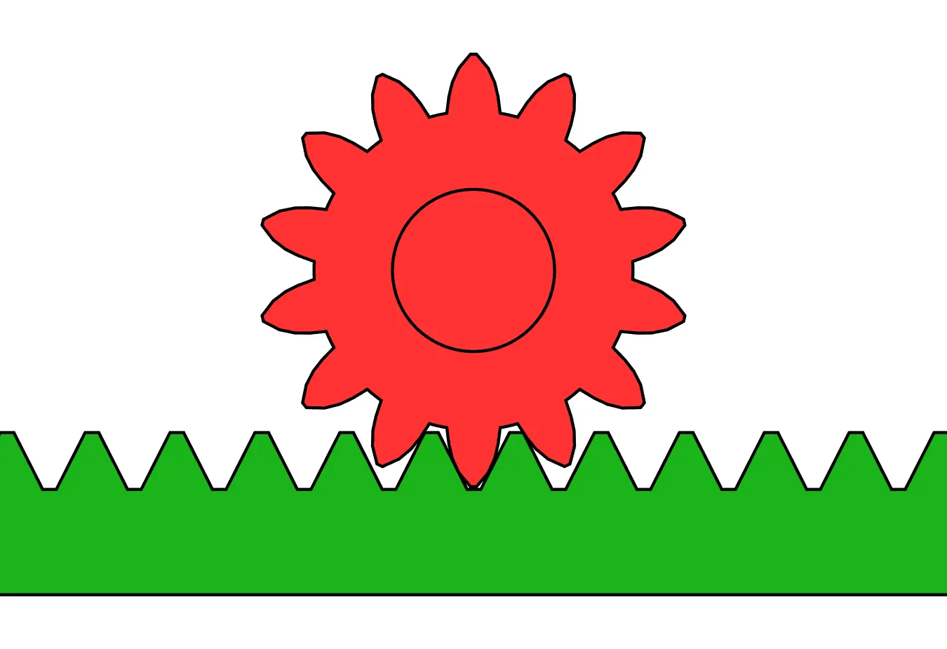
- Rack and Pinion

|
a) External Gearing b) Internal Gearing c) Rack and Pinion |
Application:
Gears are frequently used in any application to transmit power and / or torque as desired. Gears find different applications in industry depending upon type of gear mechanism.
Gear Terminology:
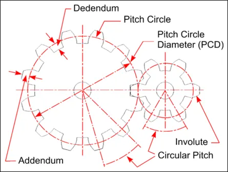
Let us define gear terminology from above set of spur gears. Gear is primarily defined by Pitch Circle diameter, module and number of teeth.
-Pitch Circle: It is an imaginary circle which by pure rolling action, would give the same motion as actual gear. The diameter of circle is called pitch circle diameter (D).
-Circular pitch(pc): Distance measured on the circumference of the pitch circle from a point of one tooth to corresponding point on the next tooth.
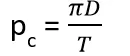 T = Number of Teeth
For two gears to mesh properly, their pitch circles should be tangent to each other. Or their circular pitch must be equal. Considering two meshing gears with Teeth T1 and T2 respectively, we can conclude.
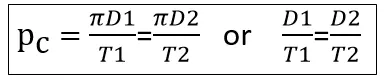 Equation 1.
-Diametric pitch(pd): It is ratio of number of teeth to the pitch circle diameter in millimetres.
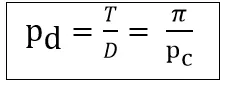 Equation 2.
-Module(m): It is ratio of pitch circle diameter in millimetres to the number of teeth.
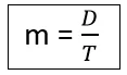 Equation 3.
Introduction to Planetary Gear system:
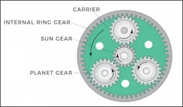
A Planetary gear train (also known as epicyclic gear) consists of two gears (sun and ring) mounted so that both the gears are concentric. A carrier connects the centres of the two gears and rotates to carry one gear, called the planet gear or planet pinion, around the other, called the sun gear.
Working:
In planetary system, one or more planet gears are rotating about sun gear with proper meshing. It also contains one outer gear called ring gear, meshing with planets internally. Planet gears are generally mounted on a carrier. Carrier may rotate so as to rotate planet gear about sun gear depending upon planetary motion.
Application:
As discussed earlier, gears are mainly used to transmit motion. Planetary gears find their application where axial transmission is required to very intricate areas. Also, it has capability to transmit high torque and high power depending upon application. Power transmission efficiency is higher compared to normal gearing because of load is carried by multiple contact points on number of planet gears.
We will be designing a simple planetary gear system containing a sun gear, a ring gear and four planets those are carried onto a carrier.
Design of Simple Planetary gear system:
Components:
- Sun gear
- Ring gear
- Carrier
- Planet gears
Inputs:
- Input speed (constant for each case) = 200 rpm (Angular velocity = 1200 deg/sec)
- Number of planet gears = 4
- Ring Gear:
- Module = 2.5 (considering metric system)
- Number of teeth (T1) = 46
- Sun Gear:
- Number of teeth (T2) = 14
Module is same for each gear to mesh properly. Pitch circles of sun-planet and planet-ring gears, are tangent to each other. Assuming pressure angle for each gear is equal i.e., φ = 20°.
Calculation for Ring gear:
Number of teeth (T1) = 46, module m=2.5 (metric system)
From equation 3, Pitch circle diameter D1= m * T = 2.5 * 46 = 115 mm
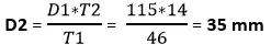
Calculation for Sun gear:
Number of teeth (T2) = 14, module m=2.5
From equation 1, Pitch circle diameter
Calculation for planet gear:
Sun, Planet and Ring gear pitch circles are tangent to each other. Let’s look into following diagram.
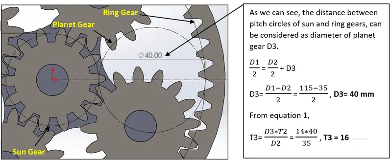
We have following data after calculation. This data is sufficient to design part models.
|
Gear Parameters |
Module (m) |
Pressure angle (φ) |
Pitch circle diameter (mm) |
Number of teeth |
|
Ring gear |
2.5 |
20° |
115 |
46 |
|
sun gear |
2.5 |
20° |
35 |
14 |
|
planet gear |
2.5 |
20° |
40 |
16 |
Using above parameters, we can design gears into Solidworks part environment.
Designing Planetary gears system components:
In this project, we have used Solidworks tool library. Make sure to install Solidworks tool box library before starting this modelling. Take a look at below image. Click on “Tool Box” and click “Add in now”.
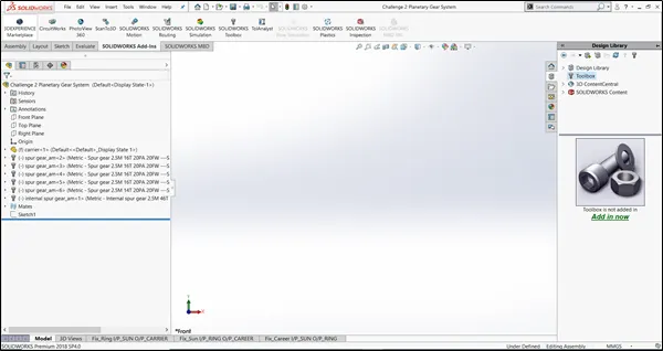
Adding in tool box, will give you options to choose from variety of standards. Choose ANSI Metric for our requirement as module of each gear is in metric system. Further it contains standard part library. It helps in modelling such predefined part. Our case, we will be using “Power Transmission”-> “Gears”.
“Gears” folder has different types of gears, such as Helical, spur, internal spur etc. As we are going to design planetary system, we will be using spur gears for sun and planet gears and internal spur for ring gear design. Accordingly, find below steps.
Design of sun gear:
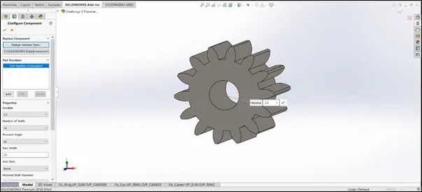
Choose spur gear from library and give below inputs.
Module = 2.5, Number of teeth = 14, Pressure angle = 20°, Face width = 20 mm, Nominal shaft diameter = 12 mm.
Design of Planet gear:
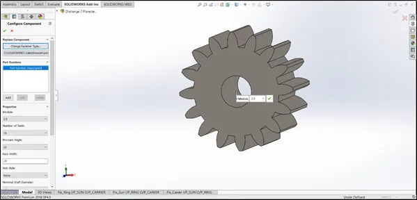
Module = 2.5, Number of teeth = 16, Pressure angle = 20°, Face width = 20 mm, Nominal shaft diameter = 12 mm.
Design of ring gear:
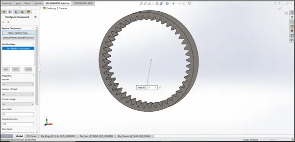
Now for ring gear, we can use Internal spur gear. Give following details.
Module = 2.5, Number of teeth = 46, Pressure angle = 20°, Face width = 20 mm, Outside diameter = 130 mm. (Outside dia. Should be more than PCD of ring gear)
Design of Carrier:
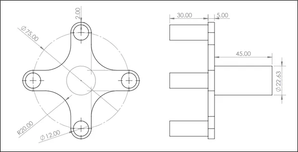
As discussed, carrier will mount planet gears on it so as to carry them. Design parameters depend upon number of planet gears, their nominal shaft diameter and their position between sun and ring gear. For our case below dimensions are used.
Assembly:
Now it’s time to assemble parts. This is a quite tricky process.
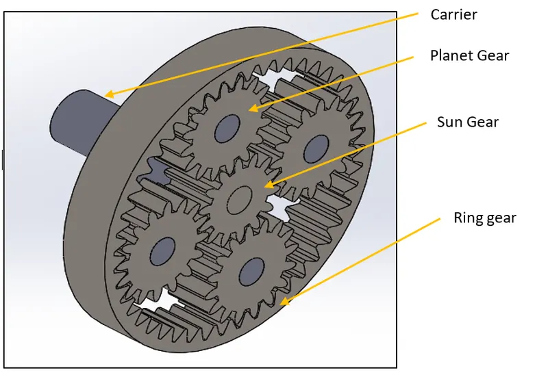
Here the carrier carries planet gears those are positioned between sun and ring gear.
Assembly approach is that we first constrain carrier so that it can only rotate about horizontal axis. As we know planet gears are carried on carrier, we will assemble planets gears with carrier.
After all the planet gears are positioned, we can assemble spur gear and ring gear. Use some reference sketches to accurately position gears.
Final assembly is as below. Make sure there is no interference between all components. Otherwise, motion study will not work accurately.
Simulating motion study:
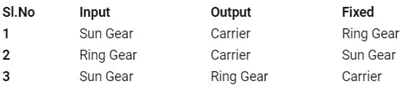
There are three different cases for our planetary gear system. Note that input speed is 200 rpm, same for each case.
We also have fundamental formula for planetary gears also called as Willis equation which says
np * zp = nc * (zp + zs) – ns * zs (Willis equation) Equation 4.
for single stage planetary gears
nr * zr = nc * (zr + zs) – zs * ns Equation 5.
|
np = angular velocity of planet (deg/sec) zp = number of teeth on planet nc = angular velocity of carrier (deg/sec) zs = number of teeth on sun gear zr = number of teeth on ring gear ns = angular velocity of sun gear (deg/sec) nr = angular velocity of ring gear (deg/sec) |
Reference link: Willis equation for planetary gear
For our motion study, we can take below parameters in terms of Willis equation.
zp = 16, zs = 14, zc = 46.
Also, we have input speed = 200 rpm = 1200 deg/sec
To fix particular component, right click component and click “fix”. That component behaves as a fixed entity throughout the motion study for that case.
Setting up motion study for three different cases and plotting output parameters:
Case 1: Ring gear fixed, input rpm given to Sun gear, angular velocity at output is measured at Carrier. Give appropriate solid body contact. Also use 120 fps and “precise contact” option for accurate result.
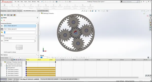
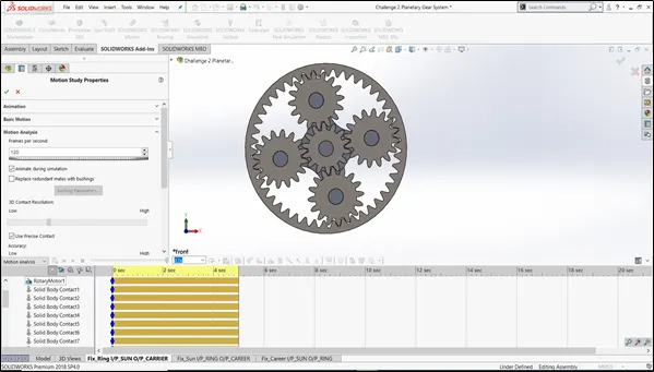
After ensuring motor, solid body contact, fps and precise contact option, run the simulation. It takes a bit more to calculate depending upon the system. After completing calculation, we can have a plot of angular velocity at carrier shaft.
Results and calculation:
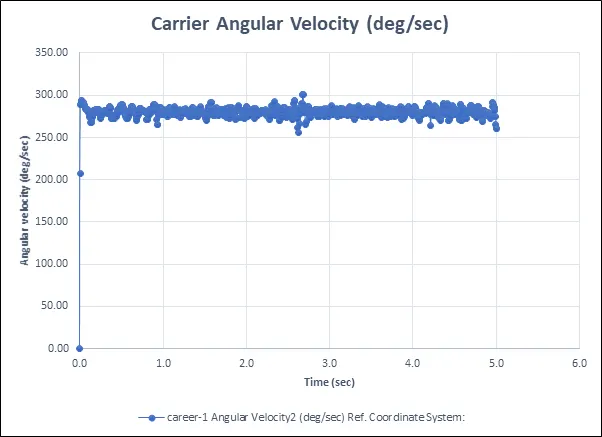
As we can observe angular velocity varies between 250 ~ 300 deg/sec during the cycle. We need to reconfirm the results by manual calculation. Below is the calculation.
From Equation 5, for case 1: nr=0 and we need nc at output,
nc * (zr + zs) = zs * ns
nc = ( zs * ns ) / (zr + zs) => (14 * 1200) / (46+14) = 280 deg/sec which matches with our actual range from graph.
Hence output given by motion study is satisfied by theoretical formula.
Case 2: sun gear fixed, motor input ring gear, output plot at carrier
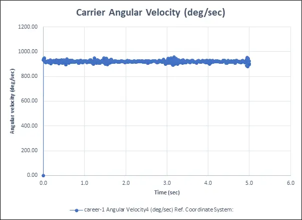
Run the motion study and we get the output plot for carrier angular velocity.
From equation 5, for case 2: ns=0 and we need nc at output,
nr * zr = nc * (zr + zs)
nc = (nr * zr) / (zr+zs) => (1200*46) / (46+14) = 920 deg/sec, which matches with our actual range from graph.
Hence output given by motion study is satisfied by theoretical formula.
Case 3: fixed carrier, motor input to sun, output plot at ring.
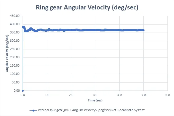
Run the motion study and we get the output plot for ring gear angular velocity.
From equation 5, for case 3: nc=0 and we need nr at output,
nr * zr = – zs * ns
nr = - ns * zs / zr = (1200*14 / 46) = -365 deg/sec, which plots inside our actual range from graph. Minus represents the direction of ring gear in opposite direction of sun gear.
Hence output given by motion study is satisfied by theoretical formula.
Video links:
Case 1 : Planetary gear system Ring gear fixed IP_Sun OP_Carrier
Case 2 : Planetary gear system Sun gear fixed, IP_Ring OP_Carrier
Case 3 : Planetary gear system Carrier fixed, IP_Sun gear OP_Ring gear
Results comparison and Conclusion:
- For case 1, input given to sun gear is transmitted to carrier when ring gear is fixed. Planet gear transmits motion by rotating about its own axis as well to roll inside ring (fixed) gear. The angular velocity at output is lowered as compared to input. i.e (1200 deg/sec is reduced to 280 deg/sec)
- For case 2, input given to ring gear is transmitted to carrier when sun gear is fixed. Angular velocity received at carrier is highest because of small gears meshing with larger gear. Output angular velocity is transmitted efficiently i.e 920 dec/sec is achieved at output.
- For case 3, input given to sun gear is transmitted to ring gear while carrier is fixed. For this case, planet gears only rotate about their own axis but not inside ring gear since carrier is fixed. Angular velocity achieved is also less because the ring gear is big. Angular velocity achieved is negative because of direction of rotation for sun and ring gear are opposite. (-365 deg / sec).
- Comparing all three cases, we can say that case 1 is useful when high amount of torque transfer is required at carrier output. While case 2 is suitable for high efficiency power transmission with minimum loss is required.
References: