Core Cavity Design For Switch Bezel Plastic Component
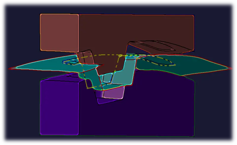
AIM: Design of Core and cavity blocks for the switch bezel plastic component using CATIA V5.
OBJECTIVE: Creating Core and Cavity Block design for Switch Bezel Plastic component from given CLASS A and Solid body part as reference.
Key Points:
- Introduction To Plastic Injection Molding Process
- What is Core, Cavity and Parting line
- Modelling methodology
- Creating Parting Surface and Parting Line
- Creating Core Block and Cavity Block
- Visual representation of Complete Core and Cavity block
- Conclusion
Introduction to Plastic Injection molding Process:
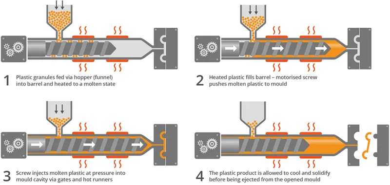
Plastic Injection molding is a process to manufacture plastic parts out of molten plastic material. The molten material is feed under high pressure, into injection mold wherein the material solidifies to a desired shape between the gap of Core and Cavity Blocks.
Injection molding machine has two main halves, called as Core half and Cavity half. Core half has the protrusion and Cavity half has a depression. When both halves are met together, the gap between these two halves shapes the desired component.
Moving Half (Core half):
In a view of Injection molding machine, core half has many provisions to facilitate the easy manufacturing of the component. Core half has the protrusion of desired component. It also carries the ejection system of the component. Core half hold the component. So, it is very important to design and manufacture core very carefully to get desired surface finish of part.
Fixed Half (Cavity Half):
In injection molding machine, cavity half is set near to feeding barrel. The Cavity half has a depression of desired component. It carries the whole feeding system which helps in determining proper flow of material up-to the core-cavity gap. Cavity half is responsible for feeding of material. So, it is important to design and manufacture cavity half to get proper material flow and avoid plastic defects.
What is Core, Cavity and Parting line:
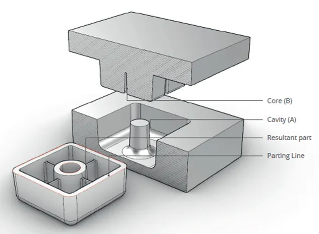
Core and Cavity are two major components involved into plastic injection molding process. A core is a protrusion while a cavity is a depression of the desired component. We will discuss both in detail.
Core:
A core is generally a protrusion which serves as an inner portion of the plastic component. Generally, it is called as B side of the component which is cosmetically less important or not directly visible to end user.
Finished plastic component tends to stick on the core part because of the shrinkage characteristic. To facilitate easy ejection of part, outer surfaces of core portion is provided with appropriate draft. Draft is given along tooling direction (i.e., direction in which mold is operating).
Cavity:
A cavity as the name suggest, has a depression in the cavity half of the mold. Cavity surface is referred to as the A side surface which is cosmetically very important because it would have direct exposure to end user. Cavity surface is manufactured such as it produces defect free surface.
Cavity is directly connected to feeding system which is responsible for material flow during operation. Cavity surfaces are also drafted and accurately surface finished to get quality output.
Parting Line (Parting Surface):
When two halves of Core and Cavity portions mate with each other, the mating surface is called parting surface. Evidently, there is a Gap between two mating halves. The line of separation of two mating halves, is called parting line.
Modelling methodology:
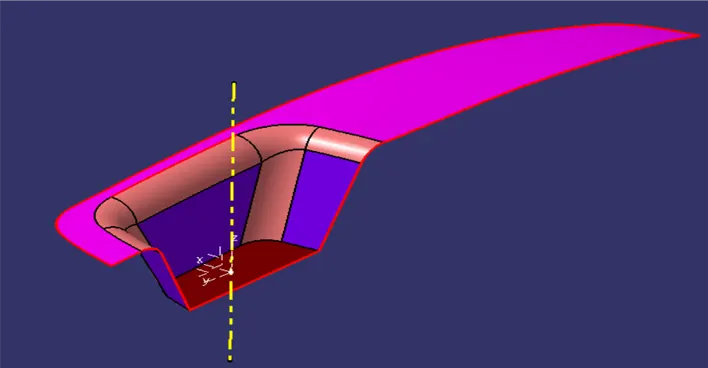
Initially, we have CLASS A surface of the component. Working on it, we have created a CLASS B and CLASS C surfaces. The final Output gives us the closed surface component. Out of that, we have created a solid part as a final output which can be manufactured.
Before generating solid component, we also have to determine Tooling Axis of the component. Tooling axis represents the direction of axis on which the mold operates. Mould opening and closing direction is generally called tooling direction.
Tooling axis plays major role in determining draft angle. Draft angle assures easy ejection of the part, ultimately producing defect free plastic component.
CLASS A Surface of the component along with Tooling Axis is shown below.
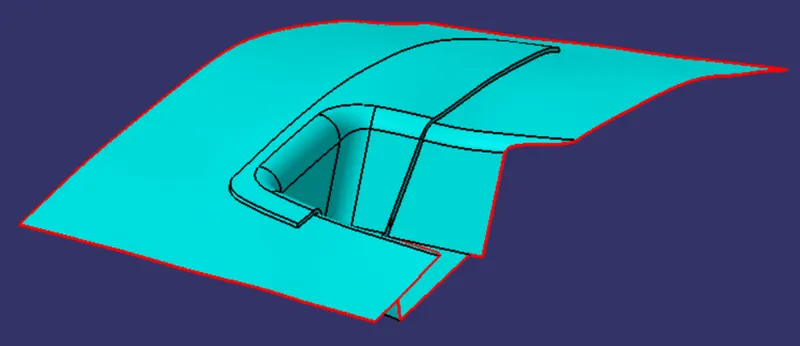
Final Output of the surface component is shown below.
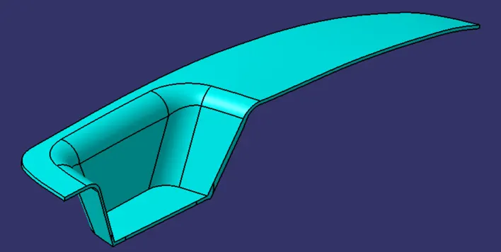
Final Solid Part out of closed surface component, which will be used to determine Core and Cavity Block as well as Parting line and Parting Surface.
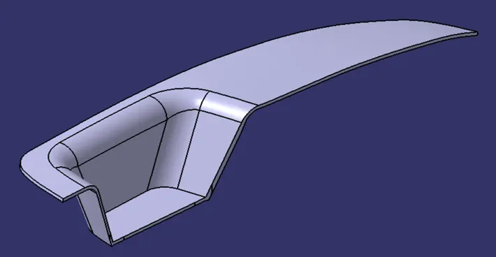
Generating draft analysis on component:
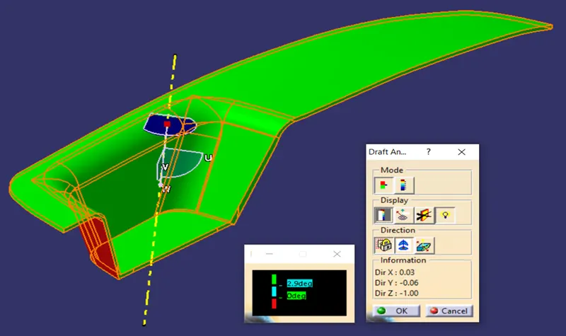
Draft analysis gives you the overall information about draft angles required with reference to main tooling axis of the component. While designing, we could give the draft angles to desired faces to clear the tooling direction. To evaluate given draft angles, we use draft analysis tool in CATIA V5.
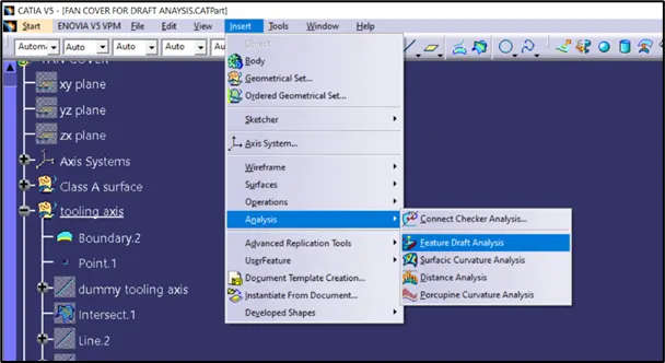
Draft analysis steps.
- Material mode plays a vital role in generating draft analysis. The tool calculates draft angles required based upon material properties and behaviour during tooling operation. Not setting up, will give you a warning message.
- After setting material mode, click on “Feature Draft analysis” from Insert menu. A dialogue box will be opened.
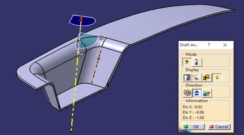
3. Use the compass option from the box, to align the current axis system with main tooling direction. It would create draft analysis with reference to tooling axis. Carefully align the axis system with main tooling axis and click on the component anywhere to create draft analysis.
Creating Parting Surface and Parting Line:
Generally, Parting surface is created on the B side of the component. The reason is that, B side surfaces are not directly visible to end user. Parting surfaces are extra flashes which comes out between two mating halves. Sometimes they need to be machined or removed after molding the component. So, It is generally considered to have parting line and Parting surface on the B side, i.e CLASS B surface of the component.
To create parting surface, we need to trim CLASSA, CLASS B and CLASS C surfaces together.
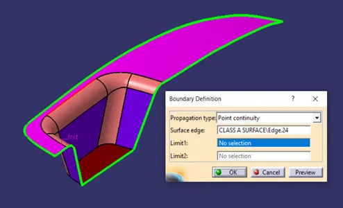
Extracting boundary from CLASS A and extrapolating it a little bit to trim with CLASS C.
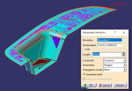
Now we can trim CLASS A and CLASS C together. And then Trim the output with CLASS B so that we can get the parting surface as output.
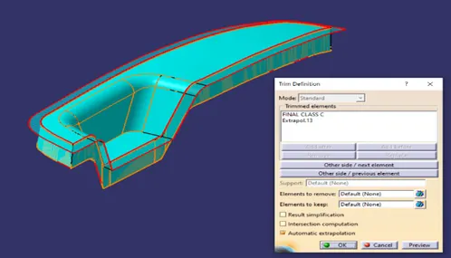
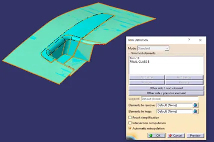
This is the final output, which represents parting surface along with component.
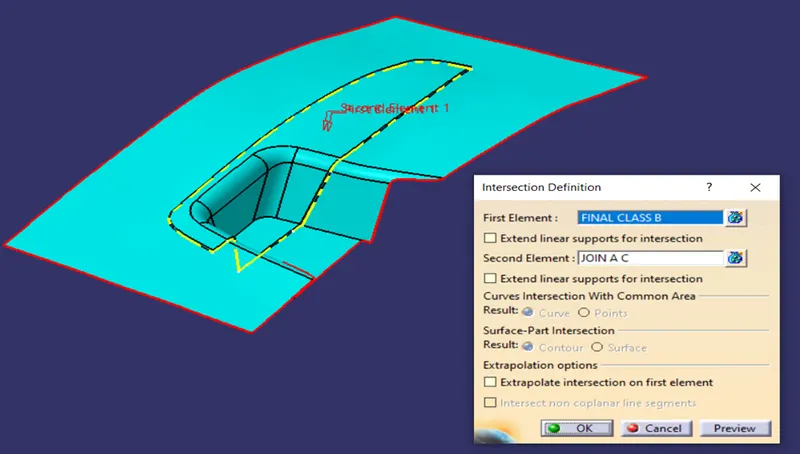
Now that we have parting surface, we can easily extract parting line. Intersect, CLASS A, CLASS B and CLASS C.
Now that we split parting surface with parting line, we get only parting surface as output.
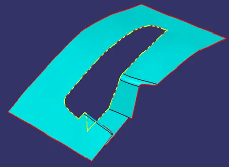
Below is the actual output as desired. Showing Parting surface (blue) and Parting line(yellow).
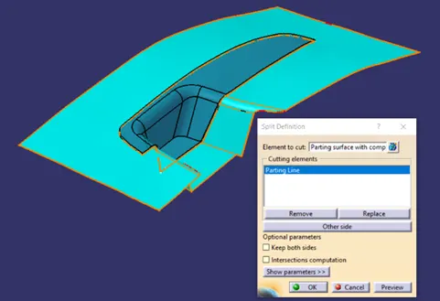
Creating Core Block and Cavity Block:
Creating Core Block:
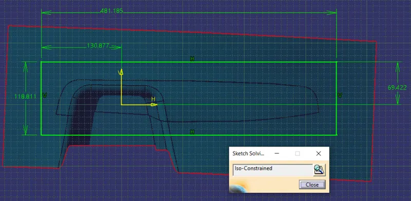
Create sketch along with the top plane. The sketch should cover the component as whole to get actual core profile.
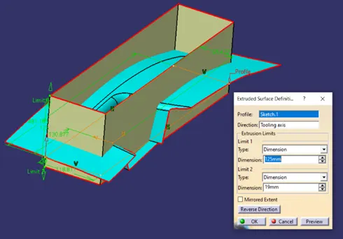
Extrude the sketch in the direction to tooling axis and trim with reference to parting surface. As output, we get the core block profile.
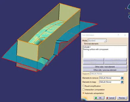
We can close the top of the extruded surface to get closed surface of core block.
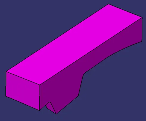
Now that we have closed surface component of core block, we can create solid body out of it. In Part design workbench, we have option “Closed Surface”. Using it, we can takeout solid part of any closed surface component.
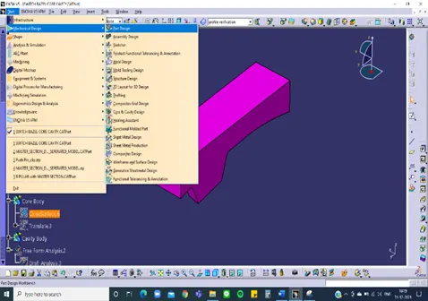
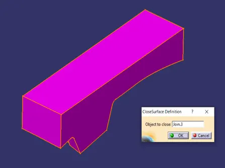
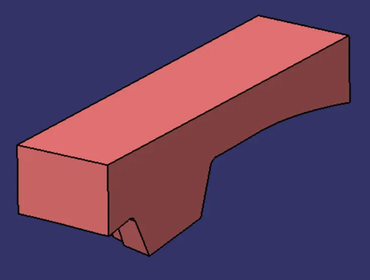
Below shows the solid body Core Block.
Creating Cavity Block:
Repeating same operations as above. The only difference is that the extrude will be on the bottom side and then trim the extrude to get cavity profile as below.
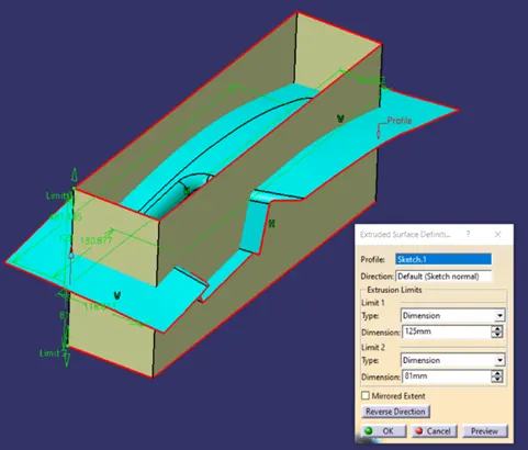
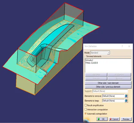
We can close the bottom part of the extruded surface to get closed surface of cavity block.
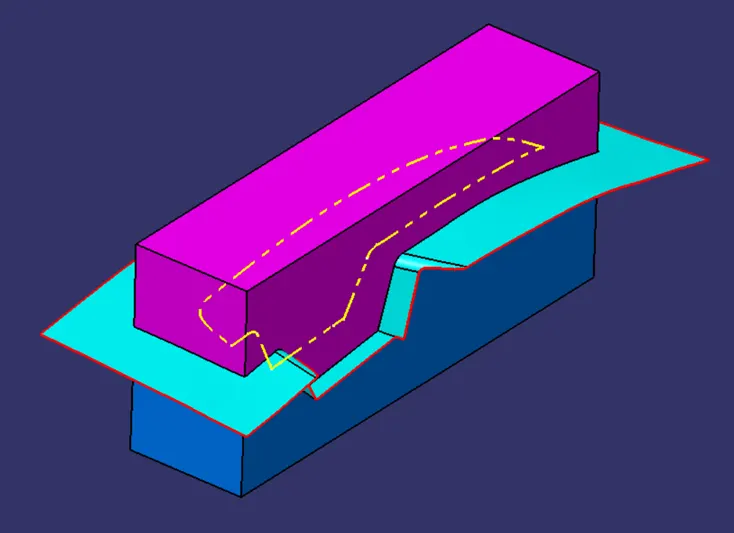
Below represents, Core block surface, Cavity block surface, along with parting surface and parting line.
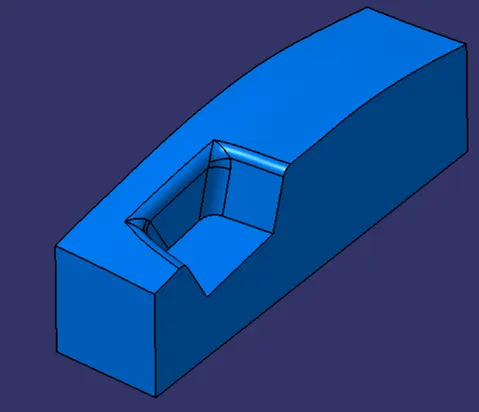
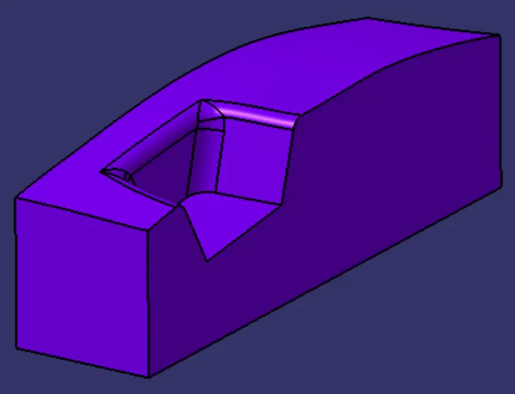
Now that we have closed surface component of cavity block, we can create solid body out of it. In Part design workbench, we have option “Closed Surface”. Using it, we can takeout solid part of any closed surface component.
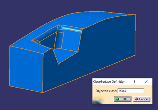
Below shows the solid body Cavity Block.
Visual representation of complete Core and Cavity Block:
Below image shows the complete Core Block and Cavity Block setup along with parting surface and parting line.
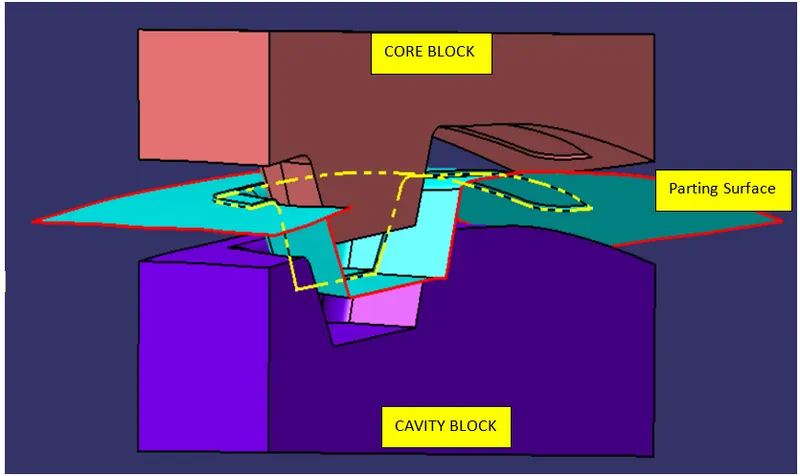
If we take an intersection of all these components, we can better understand the geometry.
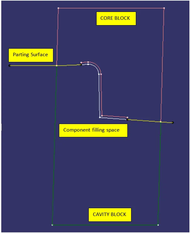
Conclusion:
- Understand the Plastic Injection molding process and its importance.
- Cleared understanding of CORE, CAVITY, PARTING LINE, PARTIG SURFACE.
- Generated Core Block, Cavity Block, Parting line and Parting Surface.
- Visual representation of Core, Cavity, Parting line along with component by taking various intersections.
Hence, we have successfully created Core and Cavity Blocks from given CLASS A and Solid body component of switch bezel. Cleared concepts of Core, Cavity, Tooling axis and Parting surface.
References: